Designation and dimensions of pipe threads. Thread inch Thread g1 2 dimensions mm
In this article, I want not only to provide dry facts about the sizes of inch pipe threads with references to standards and GOSTs, but to bring to the reader an interesting fact about the features of the designation of the latter.
So, those who have already encountered pipe threads have been more than once surprised by the discrepancy between the outer diameter of the thread and its designation. For example, a 1/2-inch thread has an outer diameter of 20.95 mm, although logically with metric threads it should be 12.7 mm. The thing is that inch threads actually indicate the through hole of the pipe, and not the outer diameter of the thread. At the same time, by adding to the size of the hole in the pipe wall, we get the overestimated outer diameter that we are accustomed to in the designation of metric threads. Conventionally, the so-called pipe inch is 33.249 mm, that is, 25.4 + 3.92+ 3.92 (where 25.4 is the passage, 3.92 is the pipe wall). The pipe walls are taken based on the working pressure for the thread. Depending on the diameter, the pipes also increase accordingly, since a pipe with a larger diameter must have thicker walls than a pipe with a smaller diameter for the same operating pressure.
Pipe threads are divided into the following:
Cylindrical pipe thread
This is an inch thread based on BSW (British Standard Whitworth) thread and corresponds to BSP (British standard pipe thread) thread, has four pitch values 28,19,14,11 threads per inch. Cuts on pipes up to size 6", pipes over 6" are welded.
The profile angle at the apex is 55°, the theoretical profile height is Н=0.960491Р.
Standards:
GOST 6357-81 - Basic standards of interchangeability.
Cylindrical pipe thread. ISO R228, EN 10226, DIN 259, BS 2779, JIS B 0202.
Symbol: letter G, numeric value conditional passage pipes in inches (inch), average diameter accuracy class (A, B), and the letters LH for left-hand threads. For example, a thread with a nominal diameter of 1 1/4", accuracy class A is designated as G1 1/4-A. Once again, we would like to remind you that it should be borne in mind that the nominal thread size corresponds to the clearance of the pipe in inches. The outer diameter of the pipe is in some proportion with this size and more accordingly to the thickness of the pipe walls.
Designation of cylindrical pipe thread size (G), steps and nominal values of outer, middle and inner thread diameters, mm
| Thread size designation | Step P | Thread diameters | |||
|---|---|---|---|---|---|
| Row 1 | Row 2 | d=D | d 2 =D 2 | d 1 =D 1 | |
| 1/16" | 0,907 | 7,723 | 7,142 | 6,561 | |
| 1/8" | 9,728 | 9,147 | 8,566 | ||
| 1/4" | 1,337 | 13,157 | 12,301 | 11,445 | |
| 3/8" | 16,662 | 15,806 | 14,950 | ||
| 1/2" | 1,814 | 20,955 | 19,793 | 18,631 | |
| 5/8" | 22,911 | 21,749 | 20,587 | ||
| 3/4" | 26,441 | 25,279 | 24,117 | ||
| 7/8" | 30,201 | 29.0З9 | 27,877 | ||
| 1" | 2,309 | 33,249 | 31,770 | 30,291 | |
| 1⅛" | 37,897 | 36,418 | 34,939 | ||
| 1¼" | 41,910 | 40,431 | 38,952 | ||
| 1⅜" | 44,323 | 42,844 | 41,365 | ||
| 1½" | 47,803 | 46,324 | 44,845 | ||
| 1¾" | 53,746 | 52,267 | 50,788 | ||
| 2" | 59,614 | 58,135 | 56,656 | ||
| 2¼" | 65,710 | 64,231 | 62,762 | ||
| 2½" | 75,184 | 73,705 | 72,226 | ||
| 2¾" | 81,534 | 80,055 | 78,576 | ||
| 3" | 87,884 | 86,405 | 84,926 | ||
| 3¼" | 93,980 | 92,501 | 91,022 | ||
| 3½" | 100,330 | 98,851 | 97,372 | ||
| 3¾" | 106,680 | 105,201 | 103,722 | ||
| 4" | 113,030 | 111,551 | 110,072 | ||
| 4½" | 125,730 | 124,251 | 122,772 | ||
| 5" | 138,430 | 136,951 | 135,472 | ||
| 5½" | 151,130 | 148,651 | 148,172 | ||
| 6" | 163,830 | 162,351 | 160,872 | ||
It would seem that there is something complicated in the pipes? Connect and twist... But, if you are not a plumber or an engineer with a specialized education, then you will definitely have questions for answers to which you will have to go wherever you look. And most likely the first thing they look at is the Internet)
Earlier we already talked about diameters metal pipes in this material. Today we will try to clarify the threaded connections of pipes for various purposes. We tried not to clutter the article with definitions. Basic terminology contains GOST 11708-82 which everyone can familiarize themselves with.
Pipe cylindrical thread. GOST 6357 - 81

Direction: Left
Accuracy class: Class A (increased), Class B (normal)
Why in inches?
The inch size came to us from Western colleagues, since the requirements of the current in the post-Soviet space GOST and are formulated on the basis of thread B.S.W.(British Standard Whitworth or Whitworth carving). Joseph Whitworth (1803 - 1887) design engineer and inventor back in 1841 demonstrated the screw profile of the same name for detachable connections and positioned it as a universal, reliable and convenient standard.
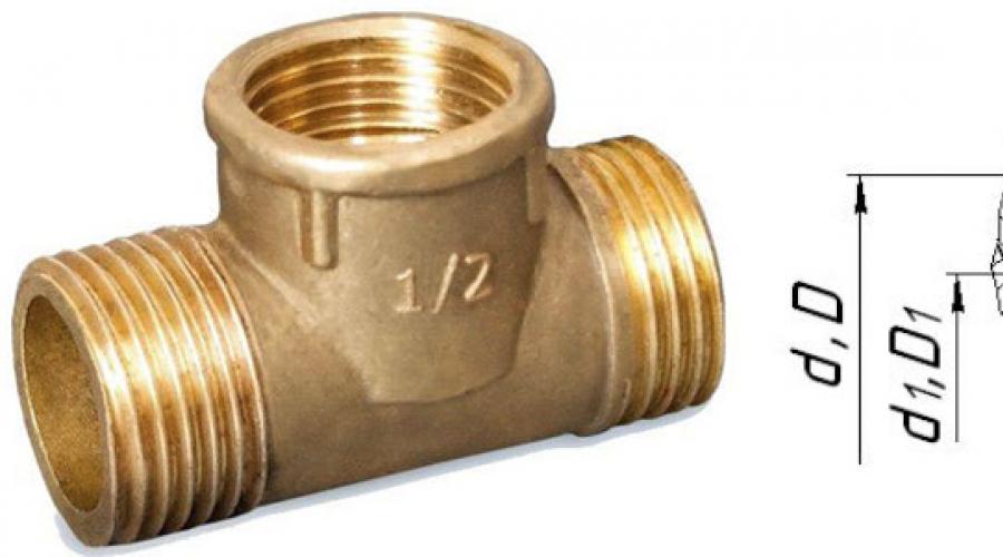
This type of thread is used both in the pipes themselves and in the elements of pipe connections: locknuts, couplings, elbows, tees ( see picture above). In the profile section we see isosceles triangle with an angle of 55 degrees and roundings at the tops and bottoms of the contour, which are made for high tightness of the connection.
Slicing threaded connection Available in sizes up to 6". All larger pipes are fixed by welding to secure the connection and prevent rupture.
Symbol in the international standard
International: G
Japan: PF
UK: BSPP
The letter G and the bore diameter (internal Ø) of the pipe are indicated in inches. The outer diameter of the thread itself is not included in the designation.
Example:
G 1/2- cylindrical external pipe thread, internal pipe Ø 1/2"". The outer diameter of the pipe will be 20.995 mm, the number of steps over a length of 25.4 mm will be 14.
The accuracy class (A, B) and the direction of turns (LH) can also be indicated.
For example:
G 1 ½ - B- cylindrical pipe thread, internal Ø 1 ½ inches, accuracy class B.
G1 ½ LH- B- cylindrical pipe thread, internal Ø 1 ½ inches, accuracy class B, left.
The make-up length is indicated by the last one in mm: G 1 ½ -B-40.
For internal pipe cylindrical threads, only the Ø of the pipe for which the hole is intended will be indicated.
Parallel Pipe Thread Size Chart
| Thread size |
Thread pitch, mm |
Threads per inch |
Thread diameters |
|||
How to determine the pitch of an inch thread

I’ll give you a picture from the English-language Internet that clearly demonstrates the technique. Pipe threads are characterized not by the size between the tops of the profile, but by the number of turns per 1 inch along the thread axis. A regular tape measure or ruler can help. Apply it, measure one inch (25.4 mm) and visually count the number of steps.
In the picture with an example ( see above) threads - from English these are literally “threads of thread”. IN in this case there are 18 of them. by one inch.
It’s even easier if you have a thread gauge for inch threads lying around in your tool box. It is very convenient to take measurements, but it must be remembered that inch threads may differ in the apex angle of 55° and 60°.
Tapered pipe threads


drawing of pipe tapered threads
Tapered pipe thread GOST 6211-81 (1st standard size)
Parameter Unit: Inch
Corresponds to the rounded profile of a cylindrical pipe thread with an angle of 55°. Cm. top part (I) of the three-dimensional image "drawing of pipe tapered threads".
Symbol
International: R
Japan: PT
UK: BSPT
The letter R and the nominal diameter Dy are indicated. The designation R means external view thread, Rc internal, Rp internal cylindrical. By analogy with cylindrical pipe threads, LH is used for left-hand threads.
Examples:
R1 ½- external pipe thread, nominal diameter Dy = 1 ½ inches.
R1 ½ LH- external pipe thread, nominal diameter Dy = 1 ½ inches, left.
Conical inch thread GOST 6111 - 52 (2nd standard size)
Parameter Unit: Inch
Has a profile angle of 60°. Cm. lower part (II) of the three-dimensional image "drawing of pipe tapered threads". It is used in pipelines (fuel, water, air) of machines and machines with relatively low pressure. Usage of this type connection assumes tightness and thread locking without additional special means(linen threads, yarn with red lead).
Symbol
Example:K ½ GOST 6111 - 52
It stands for: inch conical thread with an outer and inner diameter in the main plane approximately equal to the outer and inner Ø of a cylindrical pipe thread G ½
Table of main parameters of tapered inch threads
| Thread size designation (d, inches) | Number of threads per 1" n | Thread pitch S, mm | Thread length, mm | Outer thread diameter in the main plane d, mm | |
| Working l1 | From the end of the pipe to the main plane l2 | ||||
| 1/16 | 27 | 0,941 | 6,5 | 4,064 | 7,895 |
| 1/8 | 27 | 0,941 | 7,0 | 4,572 | 10,272 |
| 1/4 | 18 | 1,411 | 9,5 | 5,080 | 13,572 |
| 3/8 | 18 | 1,411 | 10,5 | 6,096 | 17,055 |
| 1/2 | 14 | 1,814 | 13,5 | 8,128 | 21 793 |
| 3/4 | 14 | 1,814 | 14,0 | 8,611 | 26,568 |
| 1 | 11 1/2 | 2,209 | 17,5 | 10,160 | 33,228 |
| 1 1/4 | 11 1/2 | 2,209 | 18,0 | 10,668 | 41,985 |
| 1 1/2 | 11 1/2 | 2,209 | 18,5 | 10,668 | 48,054 |
| 2 | 11 1/2 | 2,209 | 19,0 | 11,074 | 60,092 |
Metric tapered thread. GOST 25229 - 82

Parameter unit: mm
Produced on surfaces with a taper of 1:16
Used when connecting pipelines. The angle at the top of the turn is 60°. The main plane is shifted relative to the end ( see pic above).
Symbol
The letters MK are followed by an indication of the diameter in the main plane and the thread pitch in mm: MK 30x2
Metric Tapered Thread Size Chart
| Thread diameter d for row | Step P | Thread diameter in the main plane | ||||||
| 1 | 2 | d = D | d2=D2 | d1=D1 | l | l1 | l2 | |
| 6 | --- | 1 | 6,000 | 5,350 | 4,917 | 8 | 2,5 | 3 |
| 8 | --- | 8,000 | 7,350 | 6,917 | ||||
| 10 | --- | 10,000 | 9,350 | 8,917 | ||||
| 12 | --- | 1,5 | 12,000 | 11,026 | 10,376 | 11 | 3,5 | 4 |
| --- | 14 | 14,000 | 13,026 | 12,376 | ||||
| 16 | --- | 16,000 | 15,026 | 14,376 | ||||
| --- | 18 | 18,000 | 17,026 | 16,376 | ||||
| 20 | --- | 20,000 | 19,026 | 18,376 | ||||
| --- | 22 | 22,000 | 21,026 | 20,376 | ||||
| 24 | --- | 24,000 | 23,026 | 22,376 | ||||
| --- | 27 | 2 | 27,000 | 25,701 | 24,835 | 16 | 5 | 6 |
| 30 | --- | 30,000 | 28,701 | 27,835 | ||||
| --- | 33 | 33,000 | 31,701 | 30,835 | ||||
| 36 | --- | 36,000 | 34,701 | 33,835 | ||||
Characteristics of cylindrical pipe/inch threads relative to metric
The main characteristics of "inch" and "pipe" cylindrical threads in relation to "metric" threads for basic sizes.
|
Nominal thread diameter in dm |
Inch thread |
Pipe thread |
||||
|
outer diameter, mm |
number of threads per 1" |
outer diameter, mm |
number of threads per 1" |
|||
| inches | mm. | inches | mm. | inches | mm. | inches | mm. | inches | mm. |
|---|---|---|---|---|---|---|---|---|---|
| - | - | 1 | 25,4 | 2 | 50,8 | 3 | 76,2 | 4 | 101,6 |
| 1/8 | 3,2 | 1 1/8 | 28,6 | 2 1/8 | 54,0 | 3 1/8 | 79,4 | 4 1/8 | 104,8 |
| 1/4 | 6,4 | 1 1/4 | 31,8 | 2 1/4 | 57,2 | 3 1/4 | 82,6 | 4 1/4 | 108,8 |
| 3/8 | 9,5 | 1 3/8 | 34,9 | 2 3/8 | 60,3 | 3 3/8 | 85,7 | 4 3/8 | 111,1 |
| 1/2 | 12,7 | 1 1/2 | 38,1 | 2 1/2 | 63,5 | 3 1/2 | 88,9 | 4 1/2 | 114,3 |
| 5/8 | 15,9 | 1 5/8 | 41,3 | 2 5/8 | 66,7 | 3 5/8 | 92,1 | 4 5/8 | 117,5 |
| 3/4 | 19,0 | 1 3/4 | 44,4 | 2 3/4 | 69,8 | 3 3/4 | 95,2 | 4 3/4 | 120,6 |
| 7/8 | 22,2 | 1 7/8 | 47,6 | 2 7/8 | 73,0 | 3 7/8 | 98,4 | 4 7/8 | 123,8 |
Inch thread parameters
|
Outer diameter of the connected pipe |
SAE Thread Rating |
UNF thread rating |
Outer thread diameter, mm |
Average thread diameter, mm |
Thread pitch |
||
|
mm |
inch |
mm |
threads/inch |
||||
| 6 | 1/4"""" | 1/4"""" | 7/16""""-20 | 11,079 | 9,738 | 1,27 | 20 |
| 8 | 5/16"""" | 5/16"""" | 5/8""""-18 | 15,839 | 14,348 | 1,411 | 18 |
| 10 | 3/8"""" | 3/8"""" | 5/8""""-18 | 15,839 | 14,348 | 1,411 | 18 |
| 12 | 1/2"""" | 1/2"""" | 3/4""""-16 | 19,012 | 17,33 | 1,588 | 16 |
| 16 | 5/8"""" | 5/8"""" | 7/8""""-14 | 22,184 | 20,262 | 1,814 | 14 |
| 18 | 3/4"""" | 3/4"""" | 1""""-14 | 25,357 | 23,437 | 1,814 | 14 |
| 18 | 3/4"""" | --- | 1""""1/16-14 | 26,947 | 25,024 | 1,814 | 14 |
| 20 | 7/8"""" | --- | 1""""1/8-12 | 28,529 | 26,284 | 2,117 | 12 |
| 22 | 7/8"""" | 7/8"""" | 1""""1/4-12 | 31,704 | 29,459 | 2,117 | 12 |
| 22 | 7/8"""" | --- | 1""""3/8-12 | 34,877 | 32,634 | 2,117 | 12 |
| 25 | 1"""" | 1"""" | 1""""1/2-12 | 38,052 | 35,809 | 2,117 | 12 |
Copper conductors, wires and cables
| Conductor cross-section, mm | Copper conductors, wires and cables | |||
| Voltage, 220 V | Voltage, 380 V | |||
| current, A | power, kWt | current, A | power, kWt | |
| 1,5 | 19 | 4,1 | 16 | 10,5 |
| 2,5 | 27 | 5,9 | 25 | 16,5 |
| 4 | 38 | 8,3 | 30 | 19,8 |
| 6 | 46 | 10,1 | 40 | 26,4 |
| 10 | 70 | 15,4 | 50 | 33,0 |
| 16 | 85 | 18,7 | 75 | 49,5 |
| 25 | 115 | 25,3 | 90 | 59,4 |
| 35 | 135 | 29,7 | 115 | 75,9 |
| 50 | 175 | 38,5 | 145 | 95,7 |
| 70 | 215 | 47,3 | 180 | 118,8 |
| 95 | 260 | 57,2 | 220 | 145,2 |
| 120 | 300 | 66,0 | 260 | 171,6 |
Aluminum conductors, wires and cables
| Cross-section of current-carrying conductor, mm | Aluminum conductors, wires and cables | |||
| Voltage, 220 V | Voltage, 380 V | |||
| current, A | power, kWt | current, A | power, kWt | |
| 1,5 | 19 | 4,1 | 16 | 10,5 |
| 2,5 | 27 | 5,9 | 25 | 16,5 |
| 4 | 38 | 8,3 | 30 | 19,8 |
| 6 | 46 | 10,1 | 40 | 26,4 |
| 10 | 70 | 15,4 | 50 | 33,0 |
| 16 | 85 | 18,7 | 75 | 49,5 |
| 25 | 115 | 25,3 | 90 | 59,4 |
| 35 | 135 | 29,7 | 115 | 75,9 |
| 50 | 175 | 38,5 | 145 | 95,7 |
| 70 | 215 | 47,3 | 180 | 118,8 |
| 95 | 260 | 57,2 | 220 | 145,2 |
| 120 | 300 | 66,0 | 260 | 171,6 |
Inch thread sizes
| Thread diameter in mm | Thread pitch in mm | Number of threads per 1" | |||
| outer d | average d | internal d | |||
| 3/16 | 4,762 | 4,085 | 3,408 | 1,058 | 24 |
| 1/4 | 6,350 | 5,537 | 4,724 | 1,270 | 20 |
| 5/16 | 7,938 | 7,034 | 6,131 | 1,411 | 18 |
| 3/8 | 9,525 | 8,509 | 7,492 | 1,588 | 16 |
| 1/2 | 12,700 | 11,345 | 9,989 | 2,117 | 12 |
| 5,8 | 15,875 | 14,397 | 12,918 | 2,309 | 11 |
| 3/4 | 19,05 | 17,424 | 15,798 | 2,540 | 10 |
| 7/8 | 22,225 | 20,418 | 18,611 | 2,822 | 9 |
| 1 | 25,400 | 23,367 | 21,334 | 3,175 | 8 |
| 1 1/8 | 28,575 | 26,252 | 23,929 | 3,629 | 7 |
| 1 1/4 | 31,750 | 29,427 | 27,104 | 3,629 | 7 |
| 1 1/2 | 38,100 | 35,39 | 32,679 | 4,233 | 6 |
| 1 3/4 | 44,450 | 41,198 | 37,945 | 5,080 | 5 |
| 2 | 50,800 | 47,186 | 43,572 | 5,644 | 4 1/2 |
| Nominal thread diameter in inches | |||||
| Thread diameter in mm | Thread pitch in mm | Number of threads per 1" | |||
| outer d | average d | internal d | |||
| 1/8 | 9,729 | 9,148 | 8,567 | 0,907 | 28 |
| 1/4 | 13,158 | 12,302 | 11,446 | 1,337 | 19 |
| 3/8 | 16,663 | 15,807 | 14,951 | 1,337 | 19 |
| 1/2 | 20,956 | 19,794 | 18,632 | 1,814 | 14 |
| 5/8 | 22,912 | 21,750 | 20,588 | 1,814 | 14 |
| 3/4 | 26,442 | 25,281 | 24,119 | 1,814 | 14 |
| 7/8 | 30,202 | 29,040 | 27,878 | 1,814 | 14 |
| 1 | 33,250 | 31,771 | 30.293 | 2,309 | 11 |
| 1 1/8 | 37,898 | 36,420 | 34,941 | 2,309 | 11 |
| 1 1/4 | 41,912 | 40,433 | 38,954 | 2,309 | 11 |
| 1 3/8 | 44,325 | 32,846 | 41,367 | 2,309 | 11 |
| 1 1/2 | 47,805 | 46,326 | 44,847 | 2,309 | 11 |
| 1 3/4 | 53,748 | 52,270 | 50,791 | 2,309 | 11 |
| 2 | 59,616 | 58,137 | 56,659 | 2,309 | 11 |
Unit conversion table
| Conversion of energy units | Conversion of pressure units |
|---|---|
| 1 J = 0.24 cal | 1 Pa = 1 N/m*m |
| 1 kJ = 0.28 Wh | 1 Pa = 0.102 kgf/m*m |
| 1 W = 1 J/s | 1 atm =0.101 mPa =1.013 bar |
| 1 cal = 4.2 J | 1 bar = 100 kPa = 0.987 atm |
| 1 kcal/h = 1.163 W | 1 PSI = 0.06895 bar = 0.06805 atm |
Size conversion tables: simple and fast
The process of selecting the required cross-sectional sizes for threads, cables and pipes often takes a lot of time. In addition to the fact that it is necessary to select the appropriate dimensions, taking into account the parameters of the equipment, the customer has to independently convert the data into suitable units of measurement. Such a process results in significant time costs.
We simplify this task, since we suggest you use ready-made translation tables. On the page of our website you will find tables that will help you easily select the necessary threads inch pipes, copper and aluminum conductors of wires and cables. Also, you can use the conversion table inch sizes in metric, thereby accurately calculating required dimensions sections.
Unfortunately, most equipment manufacturers leave the customer alone with the calculations. Therefore, a person has to independently search the Internet for translation tables in order to select optimal sizes wire sections and pipe diameters.
We value the time of our clients, providing everyone with the opportunity to use ready-made solutions. Translated in our tables standard sizes from inches to millimeters.
On this page you will also find translations of basic energy units and pressure units, therefore, you will be able to choose the right refrigeration equipment, considering individual conditions placement and operating modes of units.
BSP British standard pipe thread- cylindrical pipe thread, also referred to as BSPP.
BSP thread interchangeable with threads of the domestic standard GOST 6357-81.
It is used in cylindrical threaded connections, as well as in connections of internal cylindrical threads with external conical threads BSPT (GOST 6211-81).
Basic standards:
GOST 6357-81 - Basic standards of interchangeability. Cylindrical pipe thread.
ISO R228
EN 10226
JIS B 0202
Thread parameters: inch thread with a profile angle at the apex of 55°, theoretical profile height H=0.960491Р.
Symbol according to GOST 6357-81: letter G, the numerical value of the nominal thread diameter in inches (inch), the accuracy class of the average diameter (A, B), and the letters LH for left-hand threads.
For example, a thread with a nominal diameter of 1.1/8", accuracy class A is designated as: G 1.1/8"-A.
The pitch of a cylindrical pipe thread according to GOST 6357-81 has four values indicated in Table 2.
The main thread dimensions of GOST 6357-81 (BSP) are given in Table 2.
Commentary on Table 2.
d is the outer diameter of the external thread (pipe);
D - outer diameter internal thread(couplings);
D 1 - internal diameter of the internal thread;
d 1 - internal diameter of the external thread;
D 2 - average diameter of internal thread;
d 2 - average diameter of the external thread.
When selecting the pipe thread size first row should be preferred second.
table 2 |
|||||||||||||||||||||||||||||||||||||||||||||||||||||||||||||||||||||||||||||||||||||||||||||||||||||||||||||||||||||||||||||||||||||||||||||||||||||||||||
Designation of the size of a cylindrical pipe thread (G), steps and nominal values of the outer, middle and inner diameters of the thread (according to GOST 6357-81), mm |
|||||||||||||||||||||||||||||||||||||||||||||||||||||||||||||||||||||||||||||||||||||||||||||||||||||||||||||||||||||||||||||||||||||||||||||||||||||||||||
|
|||||||||||||||||||||||||||||||||||||||||||||||||||||||||||||||||||||||||||||||||||||||||||||||||||||||||||||||||||||||||||||||||||||||||||||||||||||||||||
* Whitworth cut
BSPT British standard pipe tapered thread - conical pipe thread.
Based on BSW (British Standard Whitworth) threads, known as Whitworth pipe threads*.
BSPT threads are interchangeable with threads of the domestic standard GOST 6211-81.
It is used in conical threaded connections, as well as in connections between external conical threads and internal cylindrical thread according to GOST 6357-81.
Basic standards for BSPT threads:
GOST 6211-81 - Basic standards of interchangeability. Conical pipe thread.
ISO R7
DIN 2999
BS 21
JIS B 0203
Thread parameters: inch thread with a taper of 1:16 (taper angle 3°34'48"). Profile angle at the apex 55°.
Symbol according to GOST 6211-81: letter R for external thread and Rc for internal thread, numerical value of the nominal thread diameter in inches (inch), letters LH for left-hand thread. For example, a thread with a nominal diameter of 1.1/4" is designated as: R 1.1/4".
Table 1 |
||||||||||||||||||||||||||||||||||||||||||||||||||||||||||||||||||||||||||||||||||||||||||||||||||||||||||||||||
Designation of thread size, steps and nominal values of the outer, middle and inner diameters of conical pipe threads (R), mm |
||||||||||||||||||||||||||||||||||||||||||||||||||||||||||||||||||||||||||||||||||||||||||||||||||||||||||||||||
|
||||||||||||||||||||||||||||||||||||||||||||||||||||||||||||||||||||||||||||||||||||||||||||||||||||||||||||||||
*Whitworth - (Whitworth) Joseph (lived 1803-87), English engineer and industrialist. Proposed the screw thread profile in 1841 Whitworth cut. In 1851 he created a high-precision measuring machine and developed a system for standardizing threads and gauges.
NPTF National Pipe Tapered Fuel - national pipe tapered fuel thread.
NPTF - sealed thread. Compaction occurs due to compression of the threads.
Tapered fuel pipe threads are specified by ANSI/ASME B1.20.3
The NPTF fitting has a conical thread with a taper of 1:16 (cone angle φ=3°34’48").
The NPTF fitting is compatible with NPTF, NPSF or NPSM female threads.
NPTF threads are used in hydraulic systems, despite the fact that the US National Hydraulic Power Association (NFPA) does not recommend it for use in hydraulics.
On fittings with NPTF threads, to distinguish them from BSPT threads, a mark is usually placed on the edges of the hexagon
Nominal size | Outer diameter, mm | Threaded hole, mm | TPI, threads per inch | Coil pitch, mm |
NPTF thread 1/16" | ||||
NPTF 1/8" thread | ||||
NPTF 1/4" thread | ||||
NPTF 3/8" thread | ||||
NPTF 1/2" thread | ||||
NPTF 3/4" thread | ||||
NPTF 1" thread | ||||
NPTF 1.1/4" thread | ||||
NPTF 1.1/2" thread | ||||
NPTF thread 2" | ||||
NPTF 2.1/2" thread | ||||
NPTF 4" thread |
Taper thread (NPT) with a taper of 1:16 (cone angle φ=3°34'48") or cylindrical (NPS) thread. Profile angle at the apex 60°, theoretical profile height Н=0.866025Р.
Tapered NPT threads are specified by ANSI/ASME B1.20.1.
NPT thread corresponds to GOST 6111-52 - Conical inch thread with a profile angle of 60 degrees.
Nominal size | Outer diameter, mm | Threaded hole, mm | TPI, threads per inch | Coil pitch, mm |
1/16" NPT thread | ||||
1/8" NPT thread | ||||
1/4" NPT thread | ||||
NPT 3/8" thread | ||||
1/2" NPT thread | ||||
NPT 3/4" thread | ||||
1" NPT thread | ||||
NPT 1.1/4" thread | ||||
NPT 1.1/2" thread | ||||
NPT 2" thread | ||||
NPT thread 2.1/2" NPT | ||||
NPT 3" thread | ||||
NPT 3.1/2" thread | ||||
NPT 4" thread | ||||
NPT 5" thread | ||||
NPT 6" thread | ||||
NPT 8" thread | ||||
NPT 10" thread | ||||
12" NPT thread |
Metric screw threads- It has wide application both in Russia and in world practice. Metric connections are widely used pipe connections ISO 8434-1 DIN 2353.
Hydraulic connections mainly use two pitches of metric threads: pitch 1.5 and pitch 2.0.
Dimensions of commonly used hydraulic threads with a pitch of 1.5 mm: M12x1.5; M14x1.5; M16x1.5; M18x1.5; M20x1.5; M22x1.2; M24x1.5; M26x1.5; M27x1.5; M30x1.5; M33x1.5; M36x1.5; M38x1.5 M45x1.5 M52x1.5.
Dimensions of commonly used hydraulic threads with a pitch of 2.0 mm: M30x2.0; M33x2.0; M36x2.0; M42x2.0; M45x2.0; M52x2.0.
Dimensions of metric threads in fittings for domestic high pressure hoses (the so-called DK standard): DK(G)M16x1.5; DK(G)M18x1.5; DK(G)M20x1.5; DK(G)M22x1.5; DK(G)M27x1.5; DK(G)M33x1.5; DK(G)M33x2.0; DK(G)M36x1.5; DK(G)M36x2.0; DK(G)M42x2.0.
All profile parameters are measured in fractions of a meter (millimeters). Nominal diameter from 1 to 600 mm. Thread pitch from 0.0075 to 6 mm. Equilateral triangle profile (vertex angle 60°) with theoretical profile height H=0.866025404Р.
Basic standards for metric threads:
GOST 9150-2002 (ISO 68-1-98): Basic standards of interchangeability. Metric thread. Profile. Replaces GOST 9150-81 from January 1, 2004.
GOST 8724-2002 Basic standards of interchangeability. Metric thread. Diameters and steps.
GOST 9000-81 Basic standards of interchangeability. Metric thread for diameters less than 1 mm. Tolerances.
GOST 11708-82 Basic standards of interchangeability. Thread. Terms and Definitions.
GOST 16093-81 Basic standards of interchangeability. Metric thread. Tolerances. Landings with clearance.
GOST 24705-81 Basic standards of interchangeability. Metric thread. Basic dimensions.
Standards: GOST 9150-81 - Basic norms of interchangeability. Metric thread. Profile.
GOST 8724-81 - Basic standards of interchangeability. Metric thread. Diameters and steps.
ISO 965-1:1998 - ISO metric threads general purpose. Tolerances. Part 1. Principles and main characteristics.
ISO 965-2:1998 - ISO metric threads for general purposes. Tolerances. Part 2. Limit dimensions of threads for general purpose bolts and nuts. Middle class accuracy.
ISO 965-3:1998 - ISO metric threads for general purposes. Tolerances. Part 3. Deviations for structural threads.
ISO 965-4:1998 - ISO metric threads for general purposes. Tolerances. Part 4: Limit dimensions for hot-dip galvanized external screw threads for assembly with internal screw threads tapped to tolerance position H or G after galvanization.
ISO 965-5:1998 - ISO metric threads for general purposes. Tolerances. Part 5: Dimensions for internal screw threads of screws for assembly with external hot-dip galvanized screw threads, with maximum size tolerance positions h before galvanization.
ISO 68-1 - General purpose ISO screw threads. Main profile. Metric thread.
ISO 261:1998 - ISO metric threads for general purposes. General form.
ISO 262:1998 - ISO metric threads for general purposes. Selected sizes for screws, bolts and nuts.
BS 3643 - ISO metric screw threads.
DIN 13-12-1988 - Basic and precision ISO metric threads with diameters from 1 to 300 mm. Choice of diameters and pitches.
ANSI B1.13M, ANSI B1.18M - Metric M thread with a profile based on the ISO 68 standard.
Symbol: the letter M (metric), the numerical value of the nominal thread diameter in millimeters, the numerical value of the pitch (for fine-pitch threads) and the letters LH for left-hand threads. For example, a thread with a nominal diameter of 16 mm with a coarse pitch is designated as M16; thread with a nominal diameter of 36 with a fine pitch of 1.5 mm - M36x1.5; the same diameter and pitch but left-hand thread M36x1.5LH.
Notes:
1. The shape of the bolt thread root is not regulated and can be either rounded or flat-cut. A rounded cavity shape is preferred.
2. The shape of the nut thread root is not regulated.
d - outer diameter of the external thread (bolt); D - outer diameter of the internal thread (nut); d2 - average bolt diameter; D2 - average diameter of the nut; d1 - internal diameter of the bolt; D1 - internal diameter of the nut; P - thread pitch; H is the height of the original triangle; R is the nominal radius of curvature of the bolt cavity; H1 - working height of the profile
Step R | ||||||
UNF/UTS (Unified Thread Standard - inch cylindrical thread widespread in the USA and Canada.
Thread profile UN/UNF: angle at apex 60°, theoretical profile height H=0.866025P.
The apex angle and profile height fully comply with metric threads, however, all dimensions are based on the inch measurement system and are indicated in fractions of an inch.
Depending on the step, it is divided into : UNC (Unified Coarse), UNF (Unified Fine), UNEF (Unified Extra Fine), UNS (Unified Special).
Mainly used in hydraulic connections UNF thread fittings.
Nominal thread size UNF | Outer Diameter, Inch | Outer diameter, mm | Diameter of the hole for the tap (inner diameter of the nut), mm | TPI threads per inch | Coil pitch, mm |
UNF thread 0-80 | |||||
Thread UNF 1-72 | |||||
UNF 2-64 thread | |||||
UNF 3-56 thread | |||||
UNF 4-48 thread | |||||
UNF 5-44 thread | |||||
UNF 6-40 thread | |||||
UNF 8-36 thread | |||||
Thread UNF 10-32 | |||||
Thread UNF 12-28 | |||||
UNF thread 1/4"-28 | |||||
UNF thread 5/16"-24 | |||||
UNF thread 3/8"-24 | |||||
UNF thread 7/16"-20 | |||||
UNF thread 1/2"-20 | |||||
UNF thread 9/16"-18 | |||||
UNF thread 5/8"-18 | |||||
UNF thread 3/4"-16 | |||||
UNF thread 7/8"-14 | |||||
UNF thread 1"-12 | |||||
UNF thread 1.1/8"-12 | |||||
UNF thread 1.1/4"-12 | |||||
UNF thread 1.3/8"-12 | |||||
UNF thread 1.1/2"-12 |
This article will discuss concepts related to threaded connections such as metric and inch threads. To understand the intricacies associated with a threaded connection, it is necessary to consider the following concepts:
Tapered and cylindrical threads
The rod itself with tapered thread is a cone. Moreover, according to international rules, the taper should be 1 to 16, that is, for every 16 units of measurement (millimeters or inches) with increasing distance from the starting point, the diameter increases by 1 corresponding unit of measurement. It turns out that the axis around which the thread is applied and the conditional straight line drawn from the beginning of the thread to its end along the shortest path are not parallel, but are at a certain angle to each other. To explain it even more simply, if we had a threaded connection length of 16 centimeters, and the diameter of the rod at its starting point was 4 centimeters, then at the point where the thread ends, its diameter would already be 5 centimeters.
Rod with cylindrical thread is a cylinder, therefore there is no taper.
Thread pitch (metric and inch)
 The thread pitch can be large (or main) and small. Under thread pitch refers to the distance between the threads from the top of the thread to the top of the next thread. You can even measure it using a caliper (although there are also special meters). This is done as follows - the distance between several tops of the turns is measured, and then the resulting number is divided by their number. You can check the measurement accuracy using the table for the corresponding step.
| Cylindrical pipe thread according to GOST 6357-52 | |||||
|---|---|---|---|---|---|
| Designation | Number of threads N by 1" |
Thread pitch S, mm |
Outside diameter thread, mm |
Average diameter thread, mm |
Inner diameter thread, mm |
| G1/8" | 28 | 0,907 | 9,729 | 9,148 | 8,567 |
| G1/4" | 19 | 1,337 | 13,158 | 12,302 | 11,446 |
| G3/8" | 19 | 1,337 | 16,663 | 15,807 | 14,951 |
| G1/2" | 14 | 1,814 | 20,956 | 19,754 | 18,632 |
| G3/4" | 14 | 1,814 | 26,442 | 25,281 | 24,119 |
| G7/8" | 14 | 1,814 | 30,202 | 29,040 | 27,878 |
| G1" | 11 | 2,309 | 33,250 | 31,771 | 30,292 |
Nominal thread diameter
The labeling usually contains nominal diameter, which in most cases is taken to be the outer diameter of the thread. If the thread is metric, then you can use a regular caliper with scales in millimeters to measure. Also, the diameter, as well as the thread pitch, can be viewed using special tables.
Metric and inch threads with examples
 Metric thread– has the designation of the main parameters in millimeters. For example, consider an elbow fitting with an external cylindrical thread. EPL 6-GM5. In this case, EPL says that the fitting is angled, 6 is 6 mm - the outer diameter of the tube connected to the fitting. The letter “G” in its marking indicates that the thread is cylindrical. “M” indicates that the thread is metric, and the number “5” indicates the nominal thread diameter of 5 millimeters. Fittings (from those we have on sale) with the letter “G” are also equipped with a rubber o-ring, and therefore do not require fum tape. The thread pitch in this case is 0.8 millimeters.
Main settings inch thread, according to the name, are indicated in inches. This can be a 1/8, 1/4, 3/8 and 1/2 inch thread, etc. For example, let's take a fitting EPKB 8-02. EPKB is a type of fitting (in this case a splitter). The thread is conical, although there is no reference to this using the letter “R”, which would be more correct. 8 - indicates that the outer diameter of the connected tube is 8 millimeters. A 02 - that the connecting thread on the fitting is 1/4 inch. According to the table, the thread pitch is 1.337 mm. The nominal thread diameter is 13.157 mm.
The profiles of conical and cylindrical threads coincide, which allows you to screw together fittings with tapered thread and cylindrical.