Canon EF S lenses on Sony. Lens adapters (adapters, Speed Booster). Adapter with electronics
Read also
Speed controllers - in the English-speaking community are called - Electric Speed Controller (electronic speed controller) or abbreviated - ESC. The main task of the ESC is to transfer energy from the battery to the brushless motor. The need for their use arose due to some features of the BC motor. In short, the battery supplies DC current while the brushless motor accepts three-phase AC current.
Principle of operation
Communication with other components of the multicopter.
The ESC input is supplied with voltage from the battery and signals from the flight controller, and the regulator supplies the control voltage for the drive to the output. Accordingly, the regulator must ensure:
- Flight controller compatible.
- Maximum motor current (calculated from motor and propeller specifications) plus 20 – 30%.
- The current consumption is less than the current supplied by the battery divided by the number of ESCs.
*The simplest connection diagram.
What types of regulators are there?
BEC and UBEC
In addition to the main function, speed controllers can also transmit power to other components of the drone: flight controller, servos, and so on. This is achieved by introducing a battery elimination unit into the regulator - Battery Eliminator Circuit (hereinafter referred to as BEC).
The use of BEC greatly simplifies the design of the drone, however, this scheme has a number of disadvantages. The battery exclusion unit may overheat under large voltage fluctuations and heavy loads. In addition, ESCs with BEC tend to be more expensive than ESCs without a block.
Agree, it would be more logical and cheaper to make a separate ESC and a separate BEC. There is such a solution and it is called the Universal Battery Eliminator Circuit, hereinafter referred to as UBEC.
Benefits of UBEC
UBEC— connects directly to the battery and powers the desired drone unit. The advantages of this approach are quite significant:
- ESCs will overheat less since BEC will be eliminated
- UBEC have large coefficient useful action
- Hence from the previous two points, UBEC is capable of delivering more current with less risk
- No overpayment for several extra BECs located in ESC. For some flight controllers it is highly not recommended to connect more than one ESC BEC
- Less weight of regulators
Types of BEC and their advantages
BECs come in two types: linear (LBEC) and pulsed (SBEC).
- Linear converts energy into heat and turns off when overheated. Which can lead to unpleasant results: at best, the copter will not be able to take off, and at worst, an uncontrolled fall. Therefore, it began to be used in an assembly with servos, which in turn do not consume much current, preventing the unit from overheating.
- Pulse regulates voltage by quickly turning the power on and off; this approach eliminated overheating, increased output power, and made it possible to achieve an efficiency of 90%, and also pulse BECs are lighter than linear ones. Interference that occurs in the circuit, which negatively affects the operation of radio equipment, is eliminated by adding an LC filter.
Considering that many manufacturers install filters on their UBECLCs (and if there is still no filter, they can be bought cheaply and easily installed), professionals use SBEC regulators in their copters.
ESC Software
Since the speed controller performs some conversions at a high frequency and can be adjusted to various modes separate software is written for it, called firmware. This allows you to correct past errors in control algorithms, create more advanced firmware (and thus, for example, reduce battery consumption at medium gas) and make flexible settings. In copters from well-known companies such as DJI, the controller software is changed automatically using the flight controller.
Attention! Rewriting software for speed controllers can lead to various types of damage to the drone, as well as removal from warranty service! Remember that you do this at your own risk!
How to change software?
Change software the regulator can be used in several ways:
- Using a special control board
- Using a flight controller
- Using ASP programmer
The third option is simpler and is currently being actively implemented in new models.
Selecting a speed controller
Based on all of the above, we can highlight special criteria for choosing a speed controller for a drone:
- Flight controller compatible. The flight controller must support BEC and ESC firmware.
- Compatible with motor and battery specifications.
- The presence or absence of BEC and its type (LBEC or SBEC).
- Heat dissipation and sealing.
I took these regulators with the KIT of the copter on Ali (in order to play around and try out what a copter is), one burned out before the first flight, and 4 more during the training flights. Now I have time and decided to try to restore it (it’s winter, there’s nothing to do anyway).
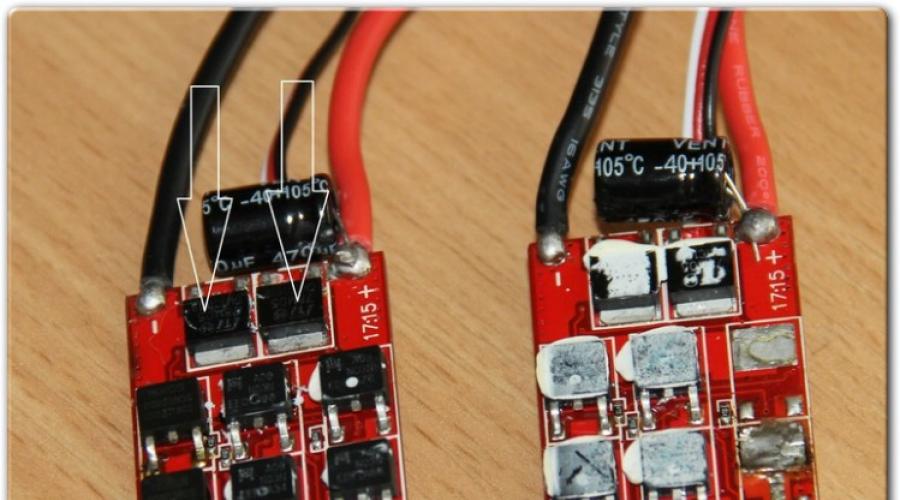
I removed the heat shrink, carefully lifted the radiator and saw the following picture:

At the top, marked with arrows, are 5-volt stabilizers 78M05, and I started testing with them.


I checked one and the other respectively. On all five burnt out regulators, the stabilizers turned out to be working. Below the stabilizers are MOSFET transistors, like these:

Two for each phase (calculated by scientific poker):

I was too lazy to figure out how MOSFETs work, so to find burnt ones I resorted to the above scientific method, took the tester and tried to measure the resistance between the legs. I was lucky right away, on the working mosfets the readings were as follows: the lower ones were about 10 kOhm

Upper mosfets about 70kOhm

Faulty mosfets showed short circuit and 3kOhm


I soldered the mosfets with a soldering iron, but of course it’s better to use a hairdryer. I didn’t have the same ones as a replacement, so I asked a friend, he soldered me these from old motherboards:

They are not 30 amps, but 50, but they fit.
On all my controllers, the mosfets flew out in pairs (one phase), on one all three phases flew out.
In total, out of five regulators, four were restored. The functionality was checked using a servo drive tester:

Then I applied thermal paste, installed the radiator and wrapped it in heat shrink:

Well, that's all.
If at least once during the process of using a quadcopter you have asked questions about the purpose of this or that part - about the ESC Motor, for example - then our article is just for you.
ESC Motor, also known as Electric Speed Controller, is a speed controller installed on brushless motors. The main task of this part is to transfer energy from the battery to a three-phase brushless motor and convert it into energy direct current. Another task of the electric speed controller is to limit the current that passes through the phases during switching.
In order to understand the operation of the ESC controller in more detail, you should first learn more about the design of the motor, which we will do in the article below.
How does a brushless quadcopter motor work?
A brushless motor has three phases (or windings) in its design. Conventionally, they are called by the Latin letters A, B and C. All conductors are connected in phases with terminals at the end. In the picture below you can see two connection methods:
The processes occurring inside a brushless motor during operation are similar to the reaction of a frame with current under the influence magnetic field- the same one from school physical experiments. When placed in a magnetic field, the frame began to rotate, and it did not perform this movement constantly, but up to a certain point. For constant rotation A current direction switch was needed.
By analogy with physical experience: In a brushless motor, the frame is the winding (or phases), and the switch is the electronics that, at certain moments, supplies constant voltage to the desired phases of the starter.
In order for the engine to operate continuously, the electronics must be able to recognize the position of the rotor. She does this using sensors - optical, magnetic, discrete, and so on. The latter, by the way, are used in most modern models.
In a brushless motor having three phases, three sensors are installed respectively. It is thanks to them that the control electronics always have accurate information about the position of the rotor, and at what moment and to which phases voltage needs to be applied.
But also among brushless motors there are also types in which sensors are not provided. In this case, the electronics determines the position of the rotor by measuring the voltage on the winding, which is not in operation at the time of testing.

When are sensors not installed?
Brushless motors, which have in their design the sensors discussed above, are considered the most modern, functional and technically equipped, but at the same time the simplest. All this makes them most preferable for installation in a radio model. However, nothing is ideal in the world, so this type of engine also has certain disadvantages.
Firstly, for correct operation, a wire must be laid from each sensor in the engine to provide power. Secondly, if at least one of the sensors fails, the entire engine will not be able to work. Thirdly, replacing the sensor requires complete disassembly of the entire engine, which means it is an expensive service at a service center.
Motors with sensors are mainly installed in those quadcopters whose startup involves heavy loads on the motor shaft.
If loads on the shaft are not provided, then a motor without sensors can be used. This subtype is also used in models in which the design does not allow the placement of an engine with sensors.
However, when installing engines of this kind, it is worth considering that at the moment of starting, oscillations or rotation of the engine axis may occur in different directions.
What characteristic would you like to improve in quadcopters?
Mandatory electronic node
Let's return to the electric speed controller. This mechanism is needed to regulate the speed of rotation of the electric magnetic field and at the same time to supply voltage to those phases that are necessary.
The design of the ESC is a microcontroller with a built-in program and MOSFET power switches.
Characterized by ESC maximum indicator current supplied from the battery to the motor.
Because of this, novice radio amateur designers often give preference to regulators with high current reserves - this is not always true. So, you can often choose a controller with a smaller margin, but it will work better. In addition, the advantage will be lower cost and lower weight.

But where controllers differ is in quality—unfortunately, there are often cases when manufacturers even skimp on thermal paste. Due to negligence in production, regulators quickly burn out. It is for this reason that if you are choosing between two ESCs with identical characteristics but at different prices- give preference to the more expensive one.
There are two types of speed controllers: BEC and UBEC. BEC - Battery Eliminator Circuit - a regulator that has a built-in voltage stabilizer in its design. The average power rating of this model is 5V, which is what powers the receiver and much other quadcopter equipment.
UBEC - Universal Battery Eliminator Circuit - removable voltage stabilizer. Some radio modelers in the design of quadcopters prefer the Universal Battery Eliminator Circuit, as they believe that this option is more reliable, since it does not depend on the temperature of the regulator.
UBECs are also divided into two types: pulse and ion. In general, they are almost identical, but the first ones are especially good for their high efficiency (which, by the way, increases with the price of the product) and lower overheating. However, in the case of this type of stabilizer, it is extremely important not to parallelize the power supply. When working with ionic stabilizers, such an installation, although not recommended, is still allowed.
The microcontroller installed in all regulators has several adjustable parameters - brake, voltage, start-up time and its rigidity, and so on.

Regulator calibration
Despite the fact that the calibration of the regulators depends on the specific model of the quadcopter on which this controller is used, there is one method that is common to all - setting up and calibrating all the regulators at once.
It is worth noting that if you have a quadcopter from DJI, then you will not need calibration.
Important note - before you begin calibrating the controllers, calibrate the radio and connect the controllers to the motors.
Before starting work, always make sure that they are safe - remove the propellers and disconnect the quadcopter from the network or USB.
Further work will take place in several stages.
In the first step, turn on the remote control remote control and move the stick responsible for supplying power to the maximum position. If, after connecting the lithium polymer battery, the lights on the flight equipment begin to light up cyclically in red, blue and yellow, then you have done everything correctly and the APM is ready for the calibration procedure.
In the second step, without touching the power stick, disconnect and reconnect the battery. This procedure will enable the calibration mode for the autopilot. Confirmation of this will be the alternate flashing of red and blue LED lights, as if on a police car.
Only after the signal sounds exactly as many times as your battery has cells (for example, for 3S there should be 3 signals), you can remove the power stick to the minimum position.
If after this you hear a single but continuous signal, it means the calibration process is complete.
As a check, give the engines a little gas - if they start to rotate, then everything is done correctly.
At the third stage, the speed controller calibration mode is exited - for this, the power stick is set to the minimum position and the battery is turned off.
More detailed instructions You can watch the video below to see how the controllers are calibrated.
Perhaps my experience in creating a speed controller for a radio-controlled model will be useful to someone.
This was almost 15 years ago, at that time commutator motors were common. Brushless motors and speed controllers were just beginning to appear and were very expensive. Then I really needed a speed controller (ESC) for the brushed motor of a radio-controlled car. I was puzzled by this question and found a diagram that I could assemble myself. Some parts were in stock, I bought some at a radio parts store, everything turned out quite cheap. Now the cost of a new regulator is not as high as before, sometimes it is cheaper to buy, but the modeler is not looking for easy ways.
The regulator circuit is as follows.
The regulator operates from 6 to 15 V. Control channel 4.8 - 6 V
The controller decided to do this circuit board. Although it could have been etched in acid (there was a drawing). To do this, you will need a single-layer fiberglass laminate.

Transistors
T 1 = BD 676 or BD 678
T 2 = BD 675 or BD 677
T 3 = BD 676 or BD 678
T 4 = BD 675 or BD 677
Resistors
P 2 = 250 kOhm
Resistance
R7 = 2.7 kOhm
Capacitors
C 3 = 0.010 mF
Chip

The first tests showed that the transistors have a very hard time; quite large loads were observed in the peaks. In this regard, they were soldered off the board, and more powerful analogues from the catalog were selected for the transistors given in the specification (KT853V and KT829A).

Since heat is released when the load increases, it needs to be removed somewhere. For this purpose I selected a radiator. I used the radiator from a computer; it was old and unnecessary anyway, lying around idle, but here it came in handy. I decided not to remove the fan from it, since the power source is 12V, so I connected it directly to the power battery. I screwed the transistors to the radiator using screws.

The radiator was cut into two parts; this was necessary due to the design of the circuit.

Long pins on top hold the cooler, and on the other side they press the transistors against the radiator for efficient cooling. At the bottom, I attached a fiberglass plate as an insulator.
The regulator needs to be calibrated using variable resistors; they allow you to configure the regulator. The first is responsible for the zero value, the second for the maximum throttle. We move the gas stick to the appropriate position and adjust the regulator.
When assembled, everything looks like this.

To create miniature models with light loads, no cooling is required. The controller without a radiator is 25 x 25 mm in size, which is quite compact.
If the ESC is subjected to high loads, then a cooling system is certainly required.
This regulator was installed on a radio-controlled car instead of an electro-mechanical switch. In general, the regulator met expectations and still performs its function.