A new method for acoustic calculation of ventilation and air conditioning systems in buildings. Acoustic calculation as a basis for designing a low-noise ventilation (air conditioning) system Acoustic calculation of ventilation methodological instructions
Ventilation systems are noisy and vibrate. The intensity and area of sound propagation depends on the location of the main units, the length of the air ducts, the overall performance, as well as the type of building and its functional purpose. The calculation of noise from ventilation is intended to select the operating mechanisms and materials used, in which it will not go beyond the standard values, and is included in the design of ventilation systems as one of the points.
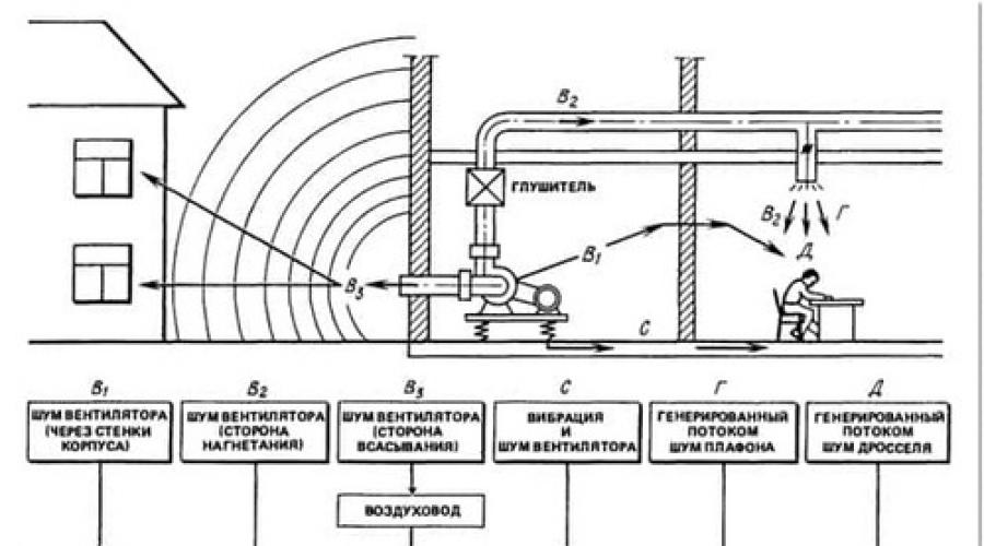
Ventilation systems consist of individual elements, each of which is a source unpleasant sounds:
- For a fan, this may be a blade or a motor. The blade makes noise due to a sharp difference in pressure from one side to the other. Engine - due to breakdown or improper installation. Refrigeration units make noise for the same reasons, with the addition of improper compressor operation.
- Air ducts. There are two reasons: the first is vortex formations from the air hitting the walls. We talked about this in more detail in the article. The second is a hum in places where the cross-section of the air duct changes. Problems are solved by reducing the gas velocity.
- Building construction. Incidental noise from vibrations of fans and other installations transmitted to building elements. The solution is achieved through the installation of special supports or gaskets to dampen vibration. A good example- air conditioning in the apartment: if external unit is not secured at all points, or the installers forgot to install protective gaskets, then its operation may cause acoustic discomfort to the owners of the installation or their neighbors.
Transfer methods
There are three ways sound travels, and in order to calculate the sound load, you need to know how exactly it is transmitted in all three ways:
- Airborne: noise from operating installations. Distributes both inside and outside the building. The main source of stress for people. For example, a large store, air conditioners and refrigeration units which are located at the rear of the building. Sound waves travel in all directions to nearby houses.
- Hydraulic: the source of noise is pipes with liquid. Sound waves are transmitted over long distances throughout the building. Caused by a change in the size of the pipeline cross-section and a malfunction of the compressor.
- Vibration: source - building construction. Caused by improper installation of fans or other system parts. It is transmitted throughout the building and beyond.
Some experts use in calculations scientific research from other countries. For example, there is a formula published in a German magazine: it is used to calculate the generation of sound by the walls of the air duct, depending on the speed of the air flow.

Measuring method
 It is often necessary to measure permissible level noise or vibration intensity in already installed, operating ventilation systems. The classic measurement method involves using special device"sound level meter": it determines the propagation force sound waves. Measurement is carried out using three filters that allow you to cut off unnecessary sounds outside the boundaries of the studied area. The first filter measures sound whose intensity does not exceed 50 dB. The second is from 50 to 85 dB. The third is over 80 dB.
Vibrations are measured in Hertz (Hz) for several points. For example, in the immediate vicinity of the noise source, then at a certain distance, after that - at the most distant point.
Rules and regulations
Rules for calculating noise from ventilation and algorithms for performing calculations are specified in SNiP 23-03-2003 “Protection from noise”; GOST 12.1.023-80 “System of occupational safety standards (SSBT). Noise. Methods for establishing the values of noise characteristics of stationary machines.”

When determining sound load near buildings it is necessary to remember that standard values given for interval operating mechanical ventilation And open windows. If we take into account closed windows And coercive system air exchange, capable of providing the design multiplicity, then other parameters are used as standards. The maximum noise level around the building increases to a limit that allows maintaining standard parameters indoors.
Requirements for the sound load level for the core and public buildings depend on their category:
- A – the best conditions.
- B - comfortable environment.
- B – noise level at the limit limit.

Acoustic calculation
Used by designers to determine noise absorption. The main task of acoustic calculation is to calculate the active spectrum of sound loads at all points determined in advance, and compare the resulting value with the standard, maximum permissible. If necessary, reduce to established standards.
The calculation is performed according to noise characteristics ventilation equipment, they must be indicated in the technical documentation.
Calculation points:
- direct installation location of the equipment;
- neighboring premises;
- all rooms where the ventilation system operates, including basements;
- air duct transit rooms;
- places of inlet inlet or exhaust outlet.
Acoustic calculations are performed using two basic formulas, the choice of which depends on the location of the point.
- The calculation point is taken inside the building, in the immediate vicinity of the fan. Sound pressure depends on the power and number of fans, wave direction and other parameters. Formula 1 for determining octave levels sound pressure from one or more fans looks like this:
where L Pi is the sound power in each octave;
∆L pomi - reduction in the intensity of the noise load associated with multidirectional movement of sound waves and power losses from propagation in the air;
According to formula 2, ∆L is determined:
where Фi is the dimensionless factor of the wave propagation vector;
S is the area of the sphere or hemisphere that covers the fan and the calculation point, m 2 ;
B is the constant value of the acoustic constant in the room, m2.
- The calculation point is taken outside the building in the nearby area. The sound from operation spreads through the walls of the ventilation shafts, grilles and fan housing. It is conventionally assumed that the source of noise is a point source (the distance from the fan to the calculated position is an order of magnitude greater than the size of the device). Then the octave noise pressure level is calculated using formula 3:
where L Pocti is the octave power of the noise source, dB;
∆L Pneti - loss of sound power as it propagates through the air duct, dB;
∆L ni - sound radiation directivity indicator, dB;
r is the length of the segment from the fan to the calculation point, m;
W is the angle of sound radiation in space;
b a - reduction in noise intensity in the atmosphere, dB/km.
If several noise sources act on one point, for example, a fan and an air conditioner, then the calculation method changes slightly. You can’t just take and add up all the sources, so experienced designers take a different path, removing all unnecessary data. The difference between the largest and smallest source in intensity is calculated, and the resulting value is compared with the standard parameter and added to the level of the largest.
Reducing the sound load from fan operation
 There is a set of measures that make it possible to level out noise factors from fan operation that are unpleasant to the human ear:
- Selection of equipment. A professional designer, unlike an amateur, always pays attention to the noise from the system and selects fans that provide standard microclimate parameters, but, at the same time, without large stock by power. Available on the market a wide range of fans with silencers, they provide good protection from unpleasant sounds and vibrations.
- Selecting an installation location. Powerful ventilation equipment it is mounted only outside the serviced premises: it can be a roof or a special chamber. For example, if you put a fan in the attic in panel house, then the residents on top floor will immediately feel discomfort. Therefore, in such cases only roof fans are used.
- Selection of air speed through channels. Designers proceed from acoustic calculations. For example, for a classic 300×900 mm air duct it is no more than 10 m/s.
- Vibration insulation, sound insulation and shielding. Vibration isolation involves installing special supports that dampen vibrations. Sound insulation is carried out by pasting the housings special material. Shielding involves cutting off the sound source from a building or room using a shield.

Calculation of noise from ventilation systems involves finding such technical solutions when the operation of the equipment will not interfere with people. This difficult task, requiring skills and experience in this field.

The Mega.ru company has long been involved in the issues of ventilation and creation optimal conditions microclimate. Our specialists solve problems of any complexity. We work in Moscow and its neighboring regions. Service technical support will answer all questions by phone numbers listed on the page. Remote collaboration is possible. Contact us!
page 1

page 2

page 3

page 4

page 5

page 6

page 7

page 8

page 9

page 10

page 11

page 12

page 13

page 14

page 15

page 16

page 17

page 18

page 19

page 20

page 21

page 22

page 23

page 24

page 25

page 26

page 27

page 28

page 29

page 30
(GOSSTROY USSR)
instructions CH 399-69
CH 399-69
MOSCOW - 1970
Official publication
STATE COMMITTEE OF THE USSR COUNCIL OF MINISTERS FOR CONSTRUCTION AFFAIRS
(GOSSTROY USSR)
INSTRUCTIONS
ON ACOUSTIC CALCULATION OF VENTILATION UNITS
Approved State Committee Council of Ministers of the USSR for Construction Affairs
PUBLISHING HOUSE OF LITERATURE ON CONSTRUCTION Moscow - 1970
dampers, grilles, lampshades, etc.) should be determined by the formula
L p = 601go + 301gC+101g/? + fi, (5)
where v - average speed air at the inlet to the device in question (installation element), calculated by the area of the supply air duct (pipe) for throttling devices and lampshades and by overall dimensions for gratings in m/sec;
£ - coefficient aerodynamic drag element of the ventilation network, related to the air speed at its inlet; for VNIIGS disk lamps (separated jet) £ = 4; for VNIIGS anemostats and lampshades (flat jet) £ = 2; for supply and exhaust grilles, the resistance coefficients are taken according to the graph in Fig. 2;
Supply grille
Exhaust grille
Rice. 2. Dependence of the grating resistance coefficient on its open cross-section
F - area cross section supply air duct in m2;
B - correction depending on the type of element, in dB; for throttling devices, anemostats and disk lamps B = 6 dB; for lampshades designed by VNIIGS B =13 dB; for lattices B=0.
2.10. Octave levels of sound power of noise emitted into the air duct by throttling devices should be determined using formula (3).
In this case, it is calculated according to formula (5), the correction AL 2 is determined from the table. 3 (the cross-sectional area of the air duct in which the element or device in question is installed should be taken into account), and corrections AL\ - according to Table_5, depending on the value of the frequency parameter f, which is determined by the equation
! = < 6 >
where f is frequency in Hz;
D - average transverse size of the air duct (equivalent diameter) in m; v is the average speed at the entrance to the element in question in m/sec.
Table 5
AL) corrections for determining the octave sound power levels of the noise of throttling devices in dB
|
||||||||||||||||||||||||||||
|
Note Intermediate values in Table 5 should be taken by interpolation |
||||||||||||||||||||||||||||
2.11. The octave levels of sound power of noise created in lampshades and grilles should be calculated using formula (2), taking the ALi corrections according to the data in Table. 6.
2.12. If the air speed in front of the air distribution or air intake device(plafond, grille, etc.) does not exceed the permissible value o additional, then the noise created in them is calculated
|
Table 6 Corrections ALi, taking into account the distribution of sound power of the noise of lampshades and grilles across octave bands, in dB |
|||||||||||||||||||||||||||||||||||||||||||||||||||||||||||||||
|
|||||||||||||||||||||||||||||||||||||||||||||||||||||||||||||||
the required reduction in sound pressure levels (see section 5) can be ignored
2.13. The permissible speed of air movement in front of the air distribution or air intake device of the installations should be determined by the formula
y D op = 0.7 10* m/sec;
^ext + 101e ~ -301ge-MIi-
where b add is the permissible octave sound pressure level in dB; n is the number of lampshades or grilles in the room in question;
B is the room constant in the octave band under consideration in m 2, adopted in accordance with paragraphs. 3.4 or 3.5;
AZ-i - correction taking into account the distribution of sound power levels of lampshades and grilles across octave bands, adopted according to table. 6, in dB;
D - correction for the location of the noise source; when the source is located in the working area (no higher than 2 m from the floor), A = 3 dB; if the source is above this zone, A *■ 0;
0.7 - safety factor;
F, B - the designations are the same as in paragraph 2.9, formula (5).
Note. The determination of the permissible air speed is carried out only for one frequency, which is equal to 250 Shch for VNIIGS lampshades, 500 Hz for disk lampshades, and 2000 Hz for anemostats and grilles.
2.14. In order to reduce the level of sound power of noise generated by turns and tees of air ducts, areas of sharp changes in cross-sectional area, etc., the speed of air movement in the main air ducts of public buildings and auxiliary buildings of industrial enterprises should be limited to 5-6 m/sec, and on branches up to 2-4 m/sec. For industrial buildings, these speeds can be doubled accordingly, if technological and other requirements allow this.
3. CALCULATION OF OCTAVE SOUND PRESSURE LEVELS AT CALCULATION POINTS
3.1. Octave sound pressure levels at permanent workplaces or premises (at design points) should not exceed those established by standards.
(Notes: 1. If regulatory requirements for sound pressure levels are different during the day, then the acoustic calculation of installations should be carried out at the lowest permissible sound pressure levels.
2. Sound pressure levels at permanent workplaces or premises (at design points) depend on the sound power and location of noise sources and the sound-absorbing qualities of the room in question.
3.2. When determining octave sound pressure levels, calculations should be made for permanent workplaces or design points in rooms closest to noise sources (heating and ventilation units, air distribution or air intake devices, air or air-thermal curtains, etc.). In the adjacent territory, the design points should be taken to be the points closest to the noise sources (fans openly located on the territory, exhaust or air intake shafts, exhaust devices of ventilation units, etc.), for which sound pressure levels are standardized.
a - noise sources (autonomous air conditioner and ceiling lamp) and the design point are located in the same room; b - noise sources (fan and installation elements) and the design point are located in different rooms; c - source of noise - the fan is located in the room, the design point is on the arrival territory; 1 - autonomous air conditioner; 2 - design point; 3 - noise-generating lamp; 4 - vibration-isolated fan; 5 - flexible insert; c -- central muffler; 7 - sudden narrowing of the air duct cross-section; 8 - branching of the air duct; 9 - rectangular turn with guide vanes; 10 - smooth rotation of the air duct; 11 - rectangular rotation of the air duct; 12 - grate; /
3.3. Octaves/Sound Pressure Levels at design points should be determined as follows.
Case 1. The noise source (noise-generating grille, lampshade, autonomous air conditioner, etc.) is located in the room under consideration (Fig. 3). Octave sound pressure levels created at a design point by one noise source should be determined using the formula
L-L, + I0! g (-£-+--i-l (8)
oct \ 4 I g g V t )
Note: For ordinary rooms that do not have special acoustic requirements, use the formula
L = Lp - 10 lg H w -4- D -(- 6, (9)
where Lp okt is the octave sound power level of the noise source (determined according to section 2) in dB\
V w - constant of the room with a noise source in the octave band under consideration (determined according to paragraphs 3.4 or 3.5) in w 2;
D - correction for the location of the noise source If the noise source is located in the working area, then for all frequencies D = 3 dB; if above the working area, - D=0;
F is the radiation directivity factor of the noise source (determined from the curves in Fig. 4), dimensionless; g - distance from the geometric center of the noise source to the calculated point in the railway.
The graphical solution of equation (8) is shown in Fig. 5.
Case 2. The design points are located in a room isolated from noise. The noise from a fan or installation element spreads through air ducts and is radiated into the room through an air distribution or air intake device (grill). Octave sound pressure levels created at design points should be determined using the formula
L = L P -ДL p + 101g(-%+-V (10)
Note: For ordinary rooms for which there are no special acoustic requirements, according to the formula
L - L p -A Lp -10 lgiJ H ~b A -f- 6, (11)
where L p in is the octave level of the sound power of the noise of a fan or installation element emitted into the air duct in the octave band under consideration in dB (determined in accordance with clauses 2.5 or 2.10);
AL р в - total reduction in the level (loss) of sound power of fan or electrical noise
installation ment in the considered octave band along the sound propagation path in dB (determined in accordance with clause 4.1); D - correction for the location of the noise source; if the air distribution or air intake device is located in the working area, A = 3 dB, if above it, D = 0; Фi is the directivity factor of the installation element (hole, grille, etc.) emitting noise into the insulated room, dimensionless (determined from the graphs in Fig. 4); r„-distance from the installation element emitting noise into the insulated room to the design point in m\
B and is the constant of the room insulated from noise in the octave band under consideration in m 2 (determined according to clauses 3.4 or 3.5).
Case 3. Calculation points are located in the area adjacent to the building. The fan noise travels through the duct and is emitted into the atmosphere through the grille or shaft (Fig. 6). Octave levels of sound pressure created at design points should be determined by the formula
I = L p -AL p -201gr a -i^- + A-8, (12)
where r a is the distance from the installation element (grid, hole) emitting noise into the atmosphere to the calculated point in m\ r a is the attenuation of sound in the atmosphere, taken according to the table. 7 in dB/km\
A is the correction in dB, taking into account the location of the calculated point relative to the axis of the noise-emitting element of the installation (for all frequencies it is taken according to Fig. 6).
1 - ventilation shaft; 2 - louvered grille
The remaining quantities are the same as in formulas (10)
|
Table 7 Attenuation of sound in the atmosphere in dB/km |
||||||||||||||||||
|
3.4. Room constant B should be determined from the graphs in Fig. 7 or according to table. 9, using table. 8 to determine the characteristics of the room.
3.5. For rooms that have special acoustic requirements (unique audience
halls, etc.), the permanent premises should be determined in accordance with the instructions for acoustic calculations for these premises.
|
||||||||||||||||||||||||||||||||||||||||||||||||||||
|
The room constant at the design frequency is equal to the room constant at a frequency of 1000 Hz multiplied by the frequency multiplier ^£=£1000 |
||||||||||||||||||||||||||||||||||||||||||||||||||||
3.6. If the design point receives noise from several noise sources (for example, supply and recirculation grilles, an autonomous air conditioner, etc.), then for the design point in question, using the appropriate formulas in clause 3.2, the octave sound pressure levels created by each of the noise sources separately should be determined , and the total level in
These “Instructions for the acoustic calculation of ventilation units” were developed by the Research Institute of Construction Physics of the USSR Gosstroy together with the Santekhproekt Institute of the USSR Gosstroy and Giproniiaviaprom of the Ministry of Aviation Industry.
The guidelines were developed to develop the requirements of the chapter of SNiP I-G.7-62 “Heating, ventilation and air conditioning. Design Standards" and "Sanitary Standards for the Design of Industrial Enterprises" (SN 245-63), which establish the need to reduce the noise of ventilation, air conditioning and air heating installations in buildings and structures for various purposes when it exceeds the sound pressure levels permitted by standards.
Editors: A. No. 1. Koshkin (Gosstroy USSR), Doctor of Engineering. sciences, prof. E. Ya. Yudin and candidates of technical sciences. Sciences E. A. Leskov and G. L. Osipov (Research Institute of Construction Physics), Ph.D. tech. Sciences I. D. Rassadi
The Guidelines set out the general principles of acoustic calculations of mechanically driven ventilation, air conditioning and air heating installations. Methods for reducing sound pressure levels at permanent workplaces and in premises (at design points) to the values established by standards are considered.
at (Giproniaviaprom) and engineer. |g. A. Katsnelson/ (GPI Santekhproekt)
1. General Provisions............ - . . , 3
2. Sources of noise from installations and their noise characteristics 5
3. Calculation of octave sound pressure levels in the calculated
points......................... 13
4. Reducing the levels (losses) of sound noise power in
various elements of air ducts........ 23
5. Determination of the required reduction in sound pressure levels. . . *. ............... 28
6. Measures to reduce sound pressure levels. 31
Application. Examples of acoustic calculations of ventilation, air conditioning and air heating installations with mechanical stimulation...... 39
Plan I quarter 1970, No. 3
|
Characteristics of premises Table 8 |
|||||||||
|
|||||||||
|
each octave band. The total sound pressure level should be determined in accordance with clause 2.7. Note. If the noise of a fan (or throttle) from one system (supply or exhaust) enters the room through several grilles, then the distribution of sound power between them should be considered uniform. |
3.7. If the calculated points are located in a room through which a “noisy” air duct passes, and noise enters the room through the walls of the air duct, then the octave sound pressure levels should be determined using the formula
L - L p -AL p + 101g --R B - 101gB„-J-3, (13)
where Lp 9 is the octave level of sound power of the noise source emitted into the air duct, in dB (determined in accordance with paragraphs 2 5 and 2.10);
ALp b - the total reduction in sound power levels (losses) along the sound propagation path from the noise source (fan, throttle, etc.) to the beginning of the considered section of the air duct emitting noise into the room, in dB (determined in accordance with section 4);
State Committee of the USSR Council of Ministers for Construction Affairs (Gosstroy USSR)
1. GENERAL PROVISIONS
1.1. These Guidelines have been developed to develop the requirements of the chapter of SNiP I-G.7-62 “Heating, ventilation and air conditioning. Design Standards" and "Sanitary Standards for the Design of Industrial Enterprises" (SN 245-63), which establish the need to reduce the noise of mechanically driven ventilation, air conditioning and air heating installations to sound pressure levels acceptable according to the standards.
1.2. The requirements of these Guidelines apply to acoustic calculations of airborne (aerodynamic) noise generated during the operation of the installations listed in clause 1.1.
Note. These Guidelines do not cover calculations of vibration insulation of fans and electric motors (insulation of shocks and sound vibrations transmitted to building structures), as well as calculations of sound insulation of the enclosing structures of ventilation chambers.
1.3. The methodology for calculating airborne (aerodynamic) noise is based on determining the sound pressure levels of noise generated during the operation of the installations specified in clause 1.1, at permanent workplaces or in premises (at design points), determining the need to reduce these noise levels and measures to reduce sound levels pressure to values allowed by standards.
Notes: 1. Acoustic calculations should be part of the design of ventilation, air conditioning and air heating installations with mechanical drive for buildings and structures for various purposes.
Acoustic calculations should be done only for rooms with standardized noise levels.
2. Airborne (aerodynamic) fan noise and noise created by air flow in air ducts have broadband spectra.
3. In these Instructions, noise should be understood as any kind of sounds that interfere with the perception of useful sounds or break silence, as well as sounds that have a harmful or irritating effect on the human body.
1.4. When acoustically calculating a central ventilation, air conditioning and air heating installation, the shortest branch of air ducts should be considered. If the central installation serves several rooms for which regulatory noise requirements are different, then an additional calculation should be made for the branch of air ducts serving the room with the lowest noise level.
Separate calculations should be made for autonomous heating and ventilation units, autonomous air conditioners, units of air or air-thermal curtains, local suction units, units of air shower installations, which are closest to the design points or have the highest performance and sound power.
Separately, an acoustic calculation of air duct branches escaping into the atmosphere (air intake and exhaust by installations) should be carried out.
If there are throttling devices (diaphragms, throttle valves, dampers), air distribution and air intake devices (grills, shades, anemostats, etc.) between the fan and the room served, sudden changes in the cross-section of air ducts, turns and tees, an acoustic calculation of these devices should be carried out and installation elements.
1.5. Acoustic calculations should be made for each of the eight octave bands of the auditory range (for which noise levels are normalized) with geometric mean frequencies of octave bands of 63, 125, 250, 500, 1000, 2000, 4000 and 8000 Hz.
Notes: 1. For central air heating, ventilation and air conditioning systems in the presence of an extensive network of air ducts, calculations are allowed only for frequencies of 125 and 250 Hz.
2. All intermediate acoustic calculations are performed with an accuracy of 0.5 dB. The final result is rounded to the nearest whole number of decibels.
1.6. The required measures to reduce noise generated by ventilation, air conditioning and air heating installations, if necessary, should be determined for each source separately.
2. NOISE SOURCES OF INSTALLATIONS AND THEIR NOISE CHARACTERISTICS
2.1. Acoustic calculations to determine the sound pressure level of air (aerodynamic) noise should be made taking into account the noise created by:
a) fan;
b) when air flow moves in installation elements (diaphragms, throttles, dampers, air duct turns, tees, grilles, lampshades, etc.).
In addition, noise transmitted through ventilation ducts from one room to another should be taken into account.
2.2. Noise characteristics (octave sound power levels) of noise sources (fans, heating units, room air conditioners, throttling, air distribution and air intake devices, etc.) should be taken according to the passports for this equipment or according to catalog data
If there are no noise characteristics, they should be determined experimentally according to the customer’s instructions or by calculation, guided by the data given in these Guidelines.
2.3. The overall sound power level of the fan noise should be determined by the formula
L p =Z+251g#+l01gQ-K (1)
where 1^P is the overall sound power level of venous noise
Tilator in dB relative to 10“ 12 W;
L-noise criterion, depending on the type and design of the fan, in dB; should be taken according to the table. 1;
R is the total pressure created by the fan, in kg/m2;
Q - fan productivity in m^/sec;
5 - correction for fan operating mode in dB.
Table 1
|
Noise criterion values L for fans in dB |
||||||||||||||||||||||||||||
|
||||||||||||||||||||||||||||
Notes: 1. Value 6 when the fan operating mode deviates by no more than “and 20% of the maximum mode, efficiency should be taken equal to 2 dB. In fan operating mode with maximum efficiency, 6=0.
2. To facilitate calculations in Fig. Figure 1 shows a graph for determining the value 251gtf+101gQ.
3. The value obtained from formula (1) characterizes the sound power emitted by the open inlet or outlet pipe of the fan in one direction into the free atmosphere or into the room in the presence of a smooth air supply to the inlet pipe.
4. If the air supply to the inlet pipe is not smooth or the throttle is installed in the inlet pipe to the values specified in
table 1, should be added for axial fans 8 dB, for centrifugal fans 4 dB
2.4. The octave levels of sound power of fan noise emitted by the open inlet or outlet pipe of the fan L p a into the free atmosphere or into the room should be determined by the formula
(2)
where is the overall sound power level of the fan in dB;
ALi is a correction that takes into account the distribution of fan sound power across octave bands in dB, taken depending on the type of fan and the number of revolutions according to the table. 2.
table 2
ALu corrections taking into account the distribution of fan sound power across octave bands, in dB
|
Centrifugal fans | |||
|
Geometric mean hour |
Axial veins |
||
|
octave band totes in Hz |
with shoulder blades |
with shoulder blades, zag |
tillers |
|
bent forward |
pushed back | ||
|
(16 000) (3 2 000) | |||
Notes: 1. Given in table. 2 data without brackets is valid when the fan speed is in the range of 700-1400 rpm.
2. At a fan speed of 1410-2800 rpm, the entire spectrum should be shifted down an octave, and at a speed of 350-690 rpm up an octave, taking for the extreme octaves the values indicated in brackets for frequencies of 32 and 16000 Hz.
3. When the fan speed exceeds 2800 rpm, the entire spectrum should be shifted down two octaves.
2.5. Octave sound power levels of fan noise emitted into the ventilation network should be determined using the formula
Lp - L p ■- A L-± -|~ L i-2,
where AL 2 is an amendment that takes into account the effect of connecting the fan to the air duct network in dB, determined from the table. 3.
|
Table 3 Amendment D £ 2 > taking into account the effect of connecting a fan or throttling device to the air duct network in dB |
||||||||||||||||||||||||||||||||||||||||||||||||||||||||||||||||||||||||||||||||||||||||||||||||||||||||||||||||||||||||||||||||||||||||||||||||||||||||||||||||||||||||||||||||||||||||||||||||||||||||||||||||||||||||||||||||
|
||||||||||||||||||||||||||||||||||||||||||||||||||||||||||||||||||||||||||||||||||||||||||||||||||||||||||||||||||||||||||||||||||||||||||||||||||||||||||||||||||||||||||||||||||||||||||||||||||||||||||||||||||||||||||||||||
2.6. The overall level of sound power of noise emitted by the fan through the walls of the casing (casing) into the ventilation chamber should be determined using formula (1), provided that the value of the noise criterion L is taken according to table. 1 as its average value for the suction and discharge sides.
Octave levels of sound power of noise emitted by a fan into the ventilation chamber should be determined using formula (2) and table. 2.
2.7. If several fans operate simultaneously in the ventilation chamber, then for each octave band it is necessary to determine the total level
sound power of the noise emitted by all fans.
The total sound power level L cyu when operating n identical fans should be determined by the formula
£sum = Z.J + 10 Ign, (4)
where Li is the sound power level of one fan in dB-, n is the number of identical fans.
To summarize the sound power levels of noise or sound pressure created by two noise sources of different levels, you should use the table. 4.
|
Table 4 Addition of sound power or sound pressure levels |
||||||||||||||||||||||||||||||||||||||||||
|
||||||||||||||||||||||||||||||||||||||||||
|
Note. If the number of different noise levels is more than two, the addition is performed sequentially, starting with two large levels. |
2.8. Octave levels of sound power of noise emitted into the room by autonomous air conditioners, heating and ventilation units, air shower units (without air duct networks) with axial fans should be determined using formula (2) and table. 2 with a boost correction of 3 dB.
For autonomous units with centrifugal fans, the octave levels of sound power of noise emitted by the suction and discharge pipes of the fan should be determined using formula (2) and table. 2, and the total noise level is according to table. 4.
Note. When air is taken from outside by installations, no higher correction is required.
2.9. The overall sound power level of noise generated by throttling, air distribution and air intake devices (throttle valves.
The basis for designing sound attenuation of ventilation and air conditioning systems is acoustic calculation - a mandatory application to the ventilation project of any facility. The main tasks of such a calculation are: determination of the octave spectrum of airborne, structural ventilation noise at design points and its required reduction by comparing this spectrum with the permissible spectrum according to hygienic standards. After selecting construction and acoustic measures to ensure the required noise reduction, a verification calculation of the expected sound pressure levels at the same design points is carried out, taking into account the effectiveness of these measures.
The initial data for acoustic calculations are the noise characteristics of the equipment - sound power levels (SPL) in octave bands with geometric mean frequencies 63, 125, 250, 500, 1,000, 2,000, 4,000, 8,000 Hz. For indicative calculations, adjusted sound power levels of noise sources in dBA may be used.
Calculation points are located in human habitats, in particular, at the installation site of the fan (in the ventilation chamber); in rooms or areas adjacent to the fan installation site; in rooms served by a ventilation system; in rooms where air ducts pass through in transit; in the area of the device for receiving or exhausting air, or only receiving air for recirculation.
The design point is in the room where the fan is installed
In general, sound pressure levels in a room depend on the sound power of the source and the directional factor of noise emission, the number of noise sources, the location of the design point relative to the source and enclosing building structures, the size and acoustic qualities of the room.
The octave sound pressure levels created by the fan(s) at the installation location (in the ventilation chamber) are equal to:
where Фi is the directivity factor of the noise source (dimensionless);
S is the area of an imaginary sphere or part of it surrounding the source and passing through the calculated point, m 2 ;
B is the acoustic constant of the room, m2.
Calculation points are located in the area adjacent to the building
The fan noise travels through the air duct and is radiated into the surrounding space through a grille or shaft, directly through the walls of the fan housing, or an open pipe when the fan is installed outside the building.
If the distance from the fan to the design point is much larger than its dimensions, the noise source can be considered a point source.
In this case, the octave sound pressure levels at the design points are determined by the formula
where L Pocti is the octave sound power level of the noise source, dB;
∆L Pneti - total reduction in sound power level along the path of sound propagation in the air duct in the octave band under consideration, dB;
∆L ni - sound radiation directivity indicator, dB;
r - distance from the noise source to the calculated point, m;
W is the spatial angle of sound radiation;
b a - sound attenuation in the atmosphere, dB/km.
Description:
The rules and regulations in force in the country stipulate that projects must include measures to protect equipment used for human life support from noise. Such equipment includes ventilation and air conditioning systems.
Acoustic calculation as a basis for designing a low-noise ventilation (air conditioning) system
V. P. Gusev, Doctor of Engineering. sciences, head laboratory for noise protection of ventilation and engineering-technological equipment (NIISF)
The rules and regulations in force in the country stipulate that projects must include measures to protect equipment used for human life support from noise. Such equipment includes ventilation and air conditioning systems.
The basis for designing sound attenuation of ventilation and air conditioning systems is acoustic calculation - a mandatory application to the ventilation project of any facility. The main tasks of such a calculation are: determination of the octave spectrum of airborne, structural ventilation noise at design points and its required reduction by comparing this spectrum with the permissible spectrum according to hygienic standards. After selecting construction and acoustic measures to ensure the required noise reduction, a verification calculation of the expected sound pressure levels at the same design points is carried out, taking into account the effectiveness of these measures.
The materials given below do not claim to be a complete presentation of the methodology for acoustic calculation of ventilation systems (installations). They contain information that clarifies, complements or reveals in a new way various aspects of this technique using the example of the acoustic calculation of a fan as the main source of noise in a ventilation system. The materials will be used in preparing a set of rules for the calculation and design of noise attenuation of ventilation units for the new SNiP.
The initial data for acoustic calculations are the noise characteristics of the equipment - sound power levels (SPL) in octave bands with geometric mean frequencies 63, 125, 250, 500, 1,000, 2,000, 4,000, 8,000 Hz. For approximate calculations, adjusted sound power levels of noise sources in dBA are sometimes used.
Calculation points are located in human habitats, in particular, at the installation site of the fan (in the ventilation chamber); in rooms or areas adjacent to the fan installation site; in rooms served by a ventilation system; in rooms where air ducts pass through in transit; in the area of the device for receiving or exhausting air, or only receiving air for recirculation.
The design point is in the room where the fan is installed
In general, sound pressure levels in a room depend on the sound power of the source and the directional factor of noise emission, the number of noise sources, the location of the design point relative to the source and enclosing building structures, the size and acoustic qualities of the room.
The octave sound pressure levels created by the fan(s) at the installation site (in the ventilation chamber) are equal to:
where Фi is the directivity factor of the noise source (dimensionless);
S is the area of an imaginary sphere or part of it surrounding the source and passing through the calculated point, m2;
B is the acoustic constant of the room, m2.
The design point is located in the room adjacent to the room where the fan is installed
The octave levels of airborne noise penetrating through the fence into the insulated room adjacent to the room where the fan is installed are determined by the soundproofing ability of the fences of the noisy room and the acoustic qualities of the protected room, which is expressed by the formula:
| (3) |
where L w is the octave sound pressure level in the room with the noise source, dB;
R - insulation from airborne noise by the enclosing structure through which noise penetrates, dB;
S - area of the enclosing structure, m2;
B u - acoustic constant of the insulated room, m 2;
k is a coefficient that takes into account the violation of the diffuseness of the sound field in the room.
The design point is located in the room served by the system
The noise from the fan spreads through the air duct (air channel), is partially attenuated in its elements and penetrates into the serviced room through the air distribution and air intake grilles. Octave sound pressure levels in a room depend on the amount of noise reduction in the air duct and the acoustic qualities of that room:
| (4) |
where L Pi is the sound power level in the i-th octave emitted by the fan into the air duct;
D L networki - attenuation in the air channel (in the network) between the noise source and the room;
D L pomi - the same as in formula (1) - formula (2).
Attenuation in the network (in the air channel) D L P of the network is the sum of attenuation in its elements, sequentially located along the sound waves. The energy theory of sound propagation through pipes assumes that these elements do not influence each other. In fact, the sequence of shaped elements and straight sections form a single wave system, in which the principle of independence of attenuation in the general case cannot be justified in pure sinusoidal tones. At the same time, in octave (wide) frequency bands, standing waves created by individual sinusoidal components cancel each other out, and therefore an energy approach that does not take into account the wave pattern in air ducts and considers the flow of sound energy can be considered justified.
Attenuation on straight sections of air ducts made of sheet material is due to losses due to wall deformation and sound radiation outward. The reduction in sound power level D L P per 1 m length of straight sections of metal air ducts depending on frequency can be judged from the data in Fig. 1.
As you can see, in air ducts with a rectangular cross-section, the attenuation (decrease in ultrasonic noise) decreases with increasing sound frequency, while in air ducts with a round cross-section, it increases. If there is thermal insulation on metal air ducts, shown in Fig. 1 values should be increased approximately twice.
The concept of attenuation (decrease) in the level of sound energy flow cannot be identified with the concept of a change in the sound pressure level in the air channel. As a sound wave moves through a channel, the total amount of energy it carries decreases, but this is not necessarily associated with a decrease in sound pressure level. In a narrowing channel, despite the attenuation of the overall energy flow, the sound pressure level can increase due to an increase in the density of sound energy. In an expanding duct, on the other hand, the energy density (and sound pressure level) can decrease faster than the total sound power. The sound attenuation in a section with a variable cross-section is equal to:
| (5) |
where L 1 and L 2 are the average sound pressure levels in the initial and final sections of the channel section along the sound waves;
F 1 and F 2 are the cross-sectional areas at the beginning and end of the channel section, respectively.
Attenuation at turns (in elbows, bends) with smooth walls, the cross section of which is less than the wavelength, is determined by reactance such as additional mass and the occurrence of higher order modes. The kinetic energy of the flow at a turn without changing the channel cross-section increases due to the resulting unevenness of the velocity field. Square rotation acts like a low pass filter. The amount of noise reduction when turning in the plane wave range is given by an exact theoretical solution:
| (6) |
where K is the modulus of the sound transmission coefficient.
For a ≥ l /2, the value of K is zero and the incident plane sound wave is theoretically completely reflected by the rotation of the channel. Maximum noise reduction occurs when the turning depth is approximately half the wavelength. The value of the theoretical modulus of the sound transmission coefficient through rectangular turns can be judged from Fig. 2.
In real designs, according to the work, the maximum attenuation is 8-10 dB, when half the wavelength fits into the channel width. With increasing frequency, the attenuation decreases to 3-6 dB in the region of wavelengths close in magnitude to twice the channel width. Then it smoothly increases again at high frequencies, reaching 8-13 dB. In Fig. Figure 3 shows noise attenuation curves at channel turns for plane waves (curve 1) and for a random, diffuse sound incidence (curve 2). These curves are obtained based on theoretical and experimental data. The presence of a noise reduction maximum at a = l /2 can be used to reduce noise with low-frequency discrete components by adjusting the channel sizes at turns to the frequency of interest.
Noise reduction on turns less than 90° is approximately proportional to the angle of rotation. For example, the reduction in noise level at a 45° turn is equal to half the reduction at a 90° turn. On turns with angles less than 45°, noise reduction is not taken into account. For smooth turns and straight bends of air ducts with guide vanes, the noise reduction (sound power level) can be determined using the curves in Fig. 4.
In channel branches, the transverse dimensions of which are less than half the sound wavelength, the physical causes of attenuation are similar to the causes of attenuation in elbows and bends. This attenuation is determined as follows (Fig. 5).
Based on the continuity equation of the medium:
From the condition of pressure continuity (r p + r 0 = r pr) and equation (7), the transmitted sound power can be represented by the expression
and the reduction in sound power level with the cross-sectional area of the branch
(11) |
|
(12) |
|
(13) |
If there is a sudden change in the cross-section of a channel with transverse dimensions less than half-wavelengths (Fig. 6 a), a decrease in the sound power level can be determined in the same way as with branching.
The calculation formula for such a change in the channel cross-section has the form
(14) |
where m is the ratio of the larger cross-sectional area of the channel to the smaller one.
The reduction in sound power levels when channel sizes are larger than the half-wavelength of out-of-plane waves due to a sudden narrowing of the channel is
If the channel expands or smoothly narrows (Fig. 6 b and 6 d), then the decrease in the sound power level is zero, since reflection of waves with a length less than the size of the channel does not occur.
In simple elements of ventilation systems, the following reduction values are accepted at all frequencies: heaters and air coolers 1.5 dB, central air conditioners 10 dB, mesh filters 0 dB, the place where the fan adjoins the air duct network 2 dB.
Sound reflection from the end of the air duct occurs if the transverse size of the air duct is less than the sound wavelength (Fig. 7).
If a plane wave propagates, then there is no reflection in a large duct, and we can assume that there are no reflection losses. However, if an opening connects a large room and an open space, then only diffuse sound waves directed towards the opening, the energy of which is equal to a quarter of the energy of the diffuse field, enter the opening. Therefore, in this case, the sound intensity level is weakened by 6 dB.
The directional characteristics of sound radiation from air distribution grilles are shown in Fig. 8.
When the noise source is located in space (for example, on a column in a large room) S = 4p r 2 (radiation into a full sphere); in the middle part of the wall, ceiling S = 2p r 2 (radiation into the hemisphere); in a dihedral angle (radiation into 1/4 sphere) S = p r 2 ; in a trihedral angle S = p r 2 /2.
The attenuation of the noise level in the room is determined by formula (2). The design point is selected in the place of permanent residence of people, closest to the noise source, at a distance of 1.5 m from the floor. If noise at the design point is created by several gratings, then the acoustic calculation is made taking into account their total impact.
When the source of noise is a section of a transit air duct passing through a room, the initial data for calculation using formula (1) are the octave levels of sound power of the noise emitted by it, determined by the approximate formula:
(16) |
where L pi is the sound power level of the source in the i-th octave frequency band, dB;
D L’ Рnetii - attenuation in the network between the source and the transit section under consideration, dB;
R Ti - sound insulation of the structure of the transit section of the air duct, dB;
S T - surface area of the transit section opening into the room, m 2 ;
F T - cross-sectional area of the air duct section, m 2.
Formula (16) does not take into account the increase in sound energy density in the air duct due to reflections; the conditions for the incidence and transmission of sound through the duct structure are significantly different from the transmission of diffuse sound through the enclosures of the room.
Calculation points are located in the area adjacent to the building
The fan noise travels through the air duct and is radiated into the surrounding space through a grille or shaft, directly through the walls of the fan housing or an open pipe when the fan is installed outside the building.
If the distance from the fan to the design point is much larger than its dimensions, the noise source can be considered a point source.
In this case, octave sound pressure levels at design points are determined by the formula
(17) |
where L Pocti is the octave sound power level of the noise source, dB;
D L Pneti - total reduction in sound power level along the sound propagation path in the air duct in the octave band under consideration, dB;
D L ni - sound radiation directivity indicator, dB;
r - distance from the noise source to the calculated point, m;
W is the spatial angle of sound radiation;
b a - sound attenuation in the atmosphere, dB/km.
If there is a row of several fans, grilles or other extended noise source of limited size, then the third term in formula (17) is taken equal to 15 lgr.
Structure-borne noise calculation
Structural noise in rooms adjacent to ventilation chambers arises as a result of the transfer of dynamic forces from the fan to the ceiling. The octave sound pressure level in an adjacent insulated room is determined by the formula
For fans located in a technical room outside the ceiling above the insulated room:
(20) |
where L Pi is the octave sound power level of air noise emitted by the fan into the ventilation chamber, dB;
Z c is the total wave resistance of the vibration isolator elements on which the refrigeration machine is installed, N s/m;
Z per - input impedance of the floor - load-bearing slab, in the absence of a floor on an elastic foundation, floor slab - if present, N s/m;
S is the conventional floor area of the technical room above the insulated room, m 2 ;
S = S 1 for S 1 > S u /4; S = S u /4; when S 1 ≤ S u /4, or if the technical room is not located above the insulated room, but has one wall in common with it;
S 1 - area of the technical room above the insulated room, m 2 ;
S u - area of the insulated room, m 2 ;
S in - total area of the technical room, m 2 ;
R - own airborne noise insulation by the ceiling, dB.
Determining the required noise reduction
The required reduction in octave sound pressure levels is calculated separately for each noise source (fan, shaped elements, fittings), but the number of noise sources of the same type in the sound power spectrum and the magnitude of the sound pressure levels created by each of them at the design point are taken into account. In general, the required noise reduction for each source should be such that the total levels in all octave frequency bands from all noise sources do not exceed the permissible sound pressure levels.
In the presence of one noise source, the required reduction in octave sound pressure levels is determined by the formula
where n is the total number of noise sources taken into account.
When determining D L three of the required reduction in octave sound pressure levels in urban areas, the total number of noise sources n should include all noise sources that create sound pressure levels at the design point that differ by less than 10 dB.
When determining D L three for design points in a room protected from noise from the ventilation system, the total number of noise sources should include:
When calculating the required reduction in fan noise - the number of systems serving the room; noise generated by air distribution devices and fittings is not taken into account;
When calculating the required noise reduction generated by the air distribution devices of the ventilation system in question, - the number of ventilation systems serving the room; the noise of the fan, air distribution devices and shaped elements is not taken into account;
When calculating the required noise reduction generated by shaped elements and air distribution devices of the branch in question, - the number of shaped elements and chokes whose noise levels differ from one another by less than 10 dB; The noise of the fan and grilles is not taken into account.
At the same time, the total number of noise sources taken into account does not take into account noise sources that create a sound pressure level at the design point that is 10 dB lower than the permissible level when their number is no more than 3 and 15 dB less than permissible when their number is no more than 10.
As you can see, acoustic calculation is not a simple task. Acoustics specialists provide the necessary accuracy of its solution. The effectiveness of noise reduction and the cost of its implementation depend on the accuracy of the acoustic calculation performed. If the calculated required noise reduction is underestimated, the measures will not be effective enough. In this case, it will be necessary to eliminate deficiencies at the existing facility, which is inevitably associated with significant material costs. If the required noise reduction is too high, unjustified costs are built directly into the project. Thus, only due to the installation of mufflers, the length of which is 300-500 mm longer than required, additional costs at medium and large facilities can amount to 100-400 thousand rubles or more.
Literature
1. SNiP II-12-77. Noise protection. M.: Stroyizdat, 1978.
2. SNiP 23-03-2003. Noise protection. Gosstroy of Russia, 2004.
3. Gusev V.P. Acoustic requirements and design rules for low-noise ventilation systems // ABOK. 2004. No. 4.
4. Guidelines for the calculation and design of noise attenuation of ventilation units. M.: Stroyizdat, 1982.
5. Yudin E. Ya., Terekhin A. S. Combating noise from mine ventilation units. M.: Nedra, 1985.
6. Reducing noise in buildings and residential areas. Ed. G. L. Osipova, E. Ya. Yudina. M.: Stroyizdat, 1987.
7. Khoroshev S. A., Petrov Yu. I., Egorov P. F. Combating fan noise. M.: Energoizdat, 1981.