The red light on the welding machine is on. Features of operation and possible malfunctions of welding inverters. Video: review of the Barmaley scheme
Read also
Inverter welding machines are becoming increasingly popular among welders due to their compact size, low weight and reasonable prices. Like any other equipment, these devices can fail due to improper operation or due to design flaws. In some cases, you can repair inverter welding machines yourself by studying the design of the inverter, but there are breakdowns that can only be repaired in a service center.
Welding inverters, depending on the model, work like household ones electrical network(220 V) and three-phase (380 V). The only thing that needs to be taken into account when connecting the device to a household network is its power consumption. If it exceeds the capabilities of the electrical wiring, then the unit will not operate if the network is drained.
So, the inverter welding machine includes the following main modules.
How does an inverter work?
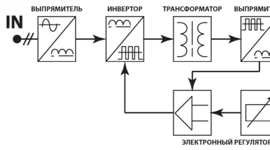
Below is a diagram that clearly shows the principle of operation of a welding inverter.

So, the operating principle of this welding machine module is as follows. The primary rectifier of the inverter receives voltage from the household electrical network or from generators, gasoline or diesel. The incoming current is alternating, but as it passes through the diode block, becomes permanent. The rectified current is supplied to the inverter, where it is converted back into alternating current, but with changed frequency characteristics, that is, it becomes high-frequency. Next, the high-frequency voltage is lowered by a transformer to 60-70 V with a simultaneous increase in current. At the next stage, the current again enters the rectifier, where it is converted into direct current, after which it is supplied to the output terminals of the unit. All current conversions controlled by a microprocessor control unit.
Causes of inverter failures
Modern inverters, especially those made on the basis of an IGBT module, are quite demanding in terms of operating rules. This is explained by the fact that when the unit is operating, its internal modules generate a lot of heat. Although radiators and a fan are used to remove heat from power components and electronic boards, these measures are sometimes not enough, especially in inexpensive units. Therefore, you need to strictly follow the rules that are indicated in the instructions for the device, which imply periodically turning off the unit to cool down.
This rule is usually called “On Duration” (DS), which is measured as a percentage. Without observing the PV, the main components of the device overheat and fail. If this happens to a new unit, then this breakdown is not subject to warranty repair.
Also, if the inverter welding machine is working in dusty rooms, dust settles on its radiators and interferes with normal heat transfer, which inevitably leads to overheating and breakdown of electrical components. If the presence of dust in the air cannot be eliminated, it is necessary to open the inverter housing more often and clean all components of the device from accumulated contaminants.

But most often inverters fail when they work at low temperatures. Breakdowns occur due to the appearance of condensation on the heated control board, resulting in a short circuit between the parts of this electronic module.
Repair features
A distinctive feature of inverters is the presence electronic board control, therefore only a qualified specialist can diagnose and fix a malfunction in this unit. In addition, diode bridges, transistor units, transformers and other parts of the electrical circuit of the device may fail. To carry out diagnostics yourself, you need to have certain knowledge and skills in working with such measuring instruments, like an oscilloscope and a multimeter.
From the above, it becomes clear that, without the necessary skills and knowledge, it is not recommended to start repairing the device, especially electronics. Otherwise, it can be completely damaged, and repairing the welding inverter will cost half the cost of a new unit.

Main malfunctions of the unit and their diagnostics
As already mentioned, inverters fail due to the impact of external factors on the “vital” units of the device. Also, malfunctions of the welding inverter can occur due to improper operation of the equipment or errors in its settings. The most common malfunctions or interruptions in the operation of inverters are:
The device does not turn on
Very often this breakdown is caused malfunction network cable apparatus. Therefore, you first need to remove the casing from the unit and ring each cable wire with a tester. But if everything is in order with the cable, then more serious diagnostics of the inverter will be required. Perhaps the problem lies in the standby power supply of the device. The method of repairing the “duty room” using the example of a Resanta brand inverter is shown in this video.
Welding arc instability or metal spattering
This malfunction may be caused incorrect setting current strength for a certain electrode diameter.
Advice! If there are no recommended current values on the packaging for the electrodes, then it can be calculated using the following formula: for each millimeter of equipment there should be welding current within 20-40 A.
It should also be taken into account welding speed. The smaller it is, the lower the current value must be set on the control panel of the unit. In addition, to ensure that the current strength corresponds to the diameter of the additive, you can use the table below.

Welding current is not adjustable
If the welding current is not regulated, the cause may be regulator failure or a violation of the contacts of the wires connected to it. It is necessary to remove the unit casing and check the reliability of the conductor connections, and, if necessary, test the regulator with a multimeter. If everything is in order with it, then this breakdown can be caused by a short circuit in the inductor or a malfunction of the secondary transformer, which will need to be checked with a multimeter. If a malfunction is detected in these modules, they must be replaced or rewound by a specialist.
High power consumption
Excessive power consumption, even if the device is without load, most often causes turn-to-turn short circuit in one of the transformers. In this case, you will not be able to repair them yourself. You need to take the transformer to a mechanic to rewind it.
The electrode sticks to the metal
This happens if the network voltage drops. To get rid of the electrode sticking to the parts being welded, you will need to correctly select and configure the welding mode (according to the instructions for the device). Also, the voltage in the network may sags if the device is connected to an extension cord with a small wire cross-section (less than 2.5 mm 2).
Often, a drop in voltage causing electrode sticking occurs when using a power extension cord that is too long. In this case, the problem is solved by connecting the inverter to the generator.
Overheat light on
If the indicator is on, this indicates overheating of the main modules of the unit. Also, the device may turn off spontaneously, which indicates when thermal protection is triggered. To prevent these interruptions in the operation of the unit from occurring in the future, it is again necessary to adhere to the correct duty cycle (ST). For example, if duty cycle = 70%, then the device should operate in the following mode: after 7 minutes of operation, the unit will be given 3 minutes to cool down.
In fact, various breakdowns and there can be quite a lot of reasons that cause them, and it is difficult to list them all. Therefore, it is better to immediately understand what algorithm is used to diagnose a welding inverter in search of faults. You can find out how the device is diagnosed by watching the following tutorial.
Equipment such as a welding machine has always been in demand. Especially if it is small in size, compact, operating at a voltage of 220 volts, which is very convenient when carrying out welding work in places where it is difficult to use bulky and powerful devices. For example, on construction sites, in car repair services, household appliances etc.
But, most importantly, the welding machine, the weight of which seems ridiculous for such equipment, sometimes it does not exceed 5 kg, due to its compactness and mobility it is easy to use when repairing personal equipment, construction individual houses, construction of some metal structures on summer cottages etc. In a word, such a welding baby will come in handy everywhere.
Now modern technologies allow to manufacture in wide range and a large number of compact and mobile welding machines that are used not only in industry, but also at home. You can practically buy them in any store for the sale of equipment. A large selection and reasonable price of welding machines allow everyone to buy them without any problems.
Currently, welding machines are very popular. different models Latvian company Resanta. This equipment High Quality. In Russia, the demand for Resanta welding machines is very high. They are convenient to transport, because their size and weight allow the equipment to be transported even in the trunk of a car. And carry it over short distances by one person.
The advantages of Resanta were appreciated not only by professional welders, but also by amateurs who do not have sufficient experience in welding work.
The company produces two types of welding equipment: Resanta welding machine and Resanta welding inverter. The difference between them is that the first type is a transformer unit, and the second is an inverter unit. Both differ from each other in various respects.
However, no matter how reliable the device is, and no matter how much safety margin it has, sooner or later some part may fail and it will need repair. Just as there is no perpetual motion machine in nature, there are no perpetual mechanisms. Breakdowns are inevitable with both the Resanta welding machine and the Resanta inverter. Let's consider general signs and the reasons for both types of welding equipment from a Latvian company, leading to repairs.
Signs and causes of welding inverter breakdowns
Signs by which you can determine that the Resanta welding inverter repair required:
- electrode sticking
- instability electric arc
- lack of arc
- device overheating
- inverter does not turn on
Causes of malfunction
Electrode sticking occurs in the following cases:
- low voltage
- using an extension cord with a cross-section of less than 2.5 mm
- burnt contacts
- poor cable contact
Arc instability is caused by:
- incorrect adjustment of welding current
- mismatch between the type and diameter of electrodes
Lack of arc in caused by the following reasons:
- cable break
- inverter overheating
- lack of "mass"
- refusal printed circuit board where one or even several parts have failed
Device overheating can happen when:
- he works long time at full load without interruption
- cooling fan failed
- there is a large layer of dust on the printed circuit board parts
Reasons when the inverter does not start after pressing the “Start” button. those. does not start working, may be as follows:
- absent completely or low voltage nutrition
- something is faulty: cable, socket or switch
- Some element has broken down on the printed circuit board
- extension cord needs to be replaced
Welding machine breakdowns
Causes of breakdowns, due to which welding units are often repaired:

Any manufacturer values his reputation and will not produce low-quality products. However, no matter how good the assembly of the same welding machine, during operation from vibration, constant transportation, etc., the contacts on terminal blocks, to which the welding cables are connected, weaken. And as a result, strong heating of the parts occurs at the junction points, which leads to their destruction and short circuit in the network, and therefore to repair. To prevent this, you need to regularly monitor the contacts on the terminals, and, if necessary, sort out and clean the connecting contacts, thereby ensuring tight contact of all parts.
It often happens that the welding machine suddenly he can switch off on his own. And this happens because in the chain high voltage a short circuit has occurred. In this case, it is necessary to identify the defective location and eliminate the malfunction.
Loosening of the bolts tightening the transformer plates, overloads in the operation of the transformer unit of the welding machine, as well as loosening of the core or the mechanism for moving the coils lead to overheating of the unit’s transformer.
If the welding machine overheats, then it needs to take a “break”. Equipment overheating is possible during his intense work. In such cases, to prevent the unit from malfunctioning, it is recommended to reduce the operating current or use electrodes of a smaller diameter, otherwise the matter may end in repair.
If the machine does not “pull”, the reason should be sought in the mains voltage or the welding current regulator.
Main types of repair work
 Some minor breakdowns of Resanta can be repaired yourself, without the help of specialists. But it also happens that serious repairs are required. In this case it is best contact service center
. There, for example, they can make a replacement:
Some minor breakdowns of Resanta can be repaired yourself, without the help of specialists. But it also happens that serious repairs are required. In this case it is best contact service center
. There, for example, they can make a replacement:
- fan
- inverter boards
- transformer
- diode rectifier
- capacitors
- and other details
And carry out repairs:
- control boards
- power supply
- control module
- IMS module
- main board
To reduce repairs to your welding machine, try to operate it correctly. And then you won’t need to spend money on repairs often.
An inverter welding machine, like any other equipment, can sooner or later malfunction. And if this happens, then the problem can be solved in two ways: take the device to a service center that specializes in repairing inverter welding machines, or try to fix the problem yourself.
Before you begin repairing the welding inverter, make sure that it is disconnected from the power supply.
Once you have mastered the necessary information, you will be able to fix some problems yourself without resorting to the help of specialists. This will, of course, save you cash. However, it can take a lot of time. Let's look at how to repair welding machines with your own hands and what malfunctions occur most often.
Features of welding inverters and their repair

Inverter welding machines make it possible to perform high-quality welding with maximum comfort, while having minimal skills in working with it.
The welding inverter is characterized by more complex, but less reliable design than welding transformers and rectifiers. An inverter, unlike its electrical predecessors, is a rather complex electronic product. If the inverter device stops working, then the first thing that needs to be tested is whether the diodes, stabilizers, transistors and other elements of the electrical circuit are working inverter welding. To do this, you need to be able to use a voltmeter, multimeter and oscilloscope.
Inverter welding has its own characteristics when carrying out repairs. For example, it often happens that it is not possible to immediately identify a non-functioning part and you have to check each element of the device circuit. Therefore, in order to carry out high-quality repairs of the inverter, it is very important to own at least basic knowledge in electronics and skills in working with electrical circuits. If you do not have this knowledge, then it is better to have the inverter repaired by specialists. Otherwise, you will simply waste time and energy, or even make the situation worse.
Each inverter must be accompanied by instructions that list possible malfunctions and recommendations for eliminating them. Return to contents
Diagnosis of faults in welding inverters

In the power supply of a welding inverter, capacitors most often fail.
Before you begin repairing inverter welding, you should know what the main types of faults are.
First, a visual inspection of the device is carried out.
If there are places with damaged contacts, the parts need to be disconnected, cleaned and reconnected.
The most vulnerable areas of an inverter welding machine include the terminal block. The welding cable is connected to it.
High current and poor contact lead to heating at the junction of the wires, which can be critical for the device.
There are several groups of all malfunctions of inverter welding machines:
- malfunctions that occur during wrong choice welding operating mode;
- breakdown or improper operation of the electronic parts of inverter welding.
In both cases welding work either difficult or completely impossible. There are several factors that contribute to the occurrence of malfunctions.
They must be diagnosed sequentially, starting with simple operations and ending with complex ones.

When testing the control unit of a welding inverter Special attention It is necessary to pay attention to the induction coils of the voltage regulator.
The causes of electrical circuit malfunction may be:
- moisture getting inside the device (operating the device during precipitation);
- dust accumulated inside the device casing disrupts the normal cooling of electrical circuit elements (usually this occurs during constant operation on construction sites);
- overheating of the inverter as a result wrong mode work.
Return to contents
The main types of breakdowns of welding inverters and their elimination
Mostly breakdowns welding inverters are a consequence of the influence of any external factors or errors during setup and operation of the devices.

Diagram of the main elements of a welding inverter.
The most common malfunctions:
- Unstable combustion welding arc or excessive spattering of electrode material. The reason is that the current does not match the type and diameter of the electrode and the welding speed. The required current strength can be found from the recommendations of the electrode manufacturer, which are indicated on the packaging. If this information is not indicated, then you can use the formula for calculating the current: 20-40 A per 1 mm of electrode diameter. When the welding speed decreases, the current must also be reduced.
- Adhesion welding electrode to metal. This may be due to several reasons. In most cases, this happens because the device is connected to a network with insufficient supply voltage. This may also be a consequence of poor contact of the device modules in the panel sockets. This problem can be eliminated by tightening the fasteners and securing the boards well. The voltage at the inverter input may drop when using a power extension cord whose wire cross-section is less than 2.5 mm 2. An excessively long extension cord can also cause a voltage drop (with a wire length of 40 m or more, operation of the device is practically impossible, since large current losses occur in the circuit). The electrode may stick due to oxidation or burning of contacts in the circuit, which can also lead to a voltage drop. This problem can also be encountered if the materials to be welded are not properly prepared (the contact between the electrode and the part deteriorates if there is an oxide film on it).
- No welding when the inverter is turned on and the indicators are working. The reasons for this in most cases are overheating of the device and spontaneous disconnection or damage to the welding cables.
- Spontaneous shutdown of the inverter. When the transformer is connected to the network, its protection is triggered and the device turns off. The cause may be a short in the circuit between the wires and the housing. Protection can be activated when there is a short circuit between sheets of magnetic wire or turns of coils and breakdown of capacitors. Remedy: disconnect the transformer from the network, find faulty element and repair it - replace the capacitor, restore the insulation, etc.
- High current consumption with little or no network load. Possible reason- short circuit of the turns on the coils. The problem is resolved by rewinding or adjusting the insulation layer.
- The reason for disconnecting the mains voltage during welding work may be an incorrectly selected circuit breaker. It should be designed for a current of up to 25 A.
- Stopping the inverter during long-term welding. Most likely the cause of this is overheating. If exceeded permissible temperature protection is triggered. Wait 20-30 minutes and continue working.
- The transformer may make a loud noise, which is accompanied by overheating of the device. One of the reasons is the weakening of the bolts that tighten the sheet elements of the magnetic wire. The reason for this may be a malfunction in the core fastener, an overload of the transformer, or a short circuit between the welding cables. Check and tighten all bolts, eliminate the fault in the core fastening, restore the insulation of the welding cables.
When buying an inverter welding machine for work in a garage or in a country house, the first thought is - wow, now I can cook everything! No welding diploma required, the device is designed for users without special education. Handling welding has become easier and more comfortable. The main thing is to understand the principle of operation and first aid in case of difficulties and breakdowns.
Inverter machines - a new generation of manual welding
Since the beginning of 2000, inverter welding machines have become cheaper and more accessible. To carry out welding work at home, it is enough to have this small and easy-to-use device and good electrodes.
Advantages of inverters
Inverter machines are lightweight, compact in size, and their scope of use and welding quality are higher than those of heavy and bulky welding transformers. They carry out their task in full: they weld cars, gates, pipe structures (for example, greenhouses or gazebos). Working with them is mobile - throwing an extendable belt over your shoulder, welding is carried out in any hard-to-reach places.
When vertical, horizontal or overhead welding, the current is reduced by 10–20%, and when welding at an angle, it is increased by the same amount compared to the normal position.
There are also no problems with the connection; the welding machine operates from a regular electrical network. It's great that it won't stop when the mains voltage drops. If the deviation is within +/- 15%, the device will continue to operate normally. The current value can be adjusted by selecting the power depending on the type and thickness of the metal. All this makes inverters ideal for both beginners and professionals.
Video: testing a homemade inverter device
How welding inverters work
The inverter apparatus connects the parts DC using electric arc welding with a coated electrode. The big plus is that at the very beginning of the process there are no power surges in the network to which the device is connected. Storage capacitor ensures uninterrupted operation electrical circuit and soft ignition of the arc with its further automatic maintenance. When connected to electrical outlet AC mains voltage with a frequency of 50 Hz is converted first into direct voltage and then into high-frequency modulated voltage. Then, using a high-frequency transformer, the current increases, the voltage decreases, and the output current is rectified. The device provides adjustment of the welding current value and protection against overheating.
The inverter device first rectifies and modulates the input current, and then increases its strength by reducing the voltage until the arc appears
The basic operating mode of inverter welding machines is MMA. This is manual arc welding with piece coating electrodes. For welding steel and cast iron products permanently or alternating current use a diameter of 1.6–5.0 mm.
The devices differ in power and cycle time. The second indicator is the period during which it is allowed to cook at the maximum permissible power in order to prevent the device from overheating. It is designated by the letters PV (on period) and is determined as a percentage relative to a time unit of 10 minutes. For example, if the device indicates a PV of 60%, this means that it can be cooked for 6 minutes and then turned off for 4 minutes. Sometimes the welding cycle is set to 5 minutes. Then a PT value of 60% means a work period of 3 and a rest period of 2 minutes. PV and duty cycle indicators are indicated in the instructions for each device.
Welding machine design
In order not to look for a repair specialist at the first difficulties in the operation of the device, it is advisable to have at least a basic understanding of its design.
DIY inverter assembly diagram
Craftsmen with knowledge of electrical engineering assemble the welding machine themselves. Not only for the sake of economy, but also at the behest creative soul. Posted on the Internet circuit diagrams inverters, drawings and instructions from those who made the inverter themselves. The main thing is to get stability of the welding arc. Most often, an “oblique bridge” circuit (“Barmaley circuit”) is used using two key transistors: bipolar or field-effect. They are placed on a radiator to remove heat; they open and close synchronously.
In the “Barmaley circuit” the main control elements are two transistors, which open and close synchronously
The electrical solution of the circuit eliminates high-voltage emissions and allows the use of relatively low-level switches. The scheme is used because of its simplicity, reliability and not very expensive consumables.
Video: review of the Barmaley scheme
DIY inverter assembly
The apparatus is assembled from the following blocks:
- power supply for stabilizing input signals. A metal partition is placed between it and other elements and blocks. The multi-winding inductor is controlled by transistors and a capacitor with stored energy. The throttle control system uses diodes;
- power unit, with the participation of which a full cycle of current conversion takes place. Assembled from a primary rectifier, an inverter transistor converter, a step-down high-frequency transformer and an output rectifier;
- Control block. It is based on a master oscillator with a special microcircuit or a pulse-width modulator. They install a resonant choke and 6–10 resonant capacitors;
- protective block. More often collected on power block, installing thermal switches for thermal protection of its elements. To avoid overloads, install a board based on the 561LA7 chip. Snubbers with resistors and capacitors K78–2 protect the converter and rectifiers.
Video: assembling a welding inverter
Reasons for failure of inverters
The design of inverter welding machines is more complex than transformer welding machines and, unfortunately, less reliable. This often leads to failure of various components for the following reasons:
- low protection from dust. When it accumulates inside, a thermal protection signal is triggered and the device turns off. Requires disassembly at least twice a year to clean the internal parts with a jet compressed air or with a soft brush;
- moisture getting inside, causing a short circuit that is dangerous for the unit;
- low quality cooling system in cheap devices. Because of this, the plastic parts of the structure melt and the emergency shutdown does not work. In models with tunnel ventilation, the radiator is located along the body, and the main components are located inside it. Such devices are much more expensive;
- voltage surges, especially drops to 190 V or more;
- overload when cutting thick metal and work for which a particular device is not designed. Then the IGBT power module fails;
- poor-quality fastening in the contacts of the pads, which provokes overheating of these places and sparking;
- sensitivity to shocks and falls due to the presence of plastic parts;
- low quality of spare parts used for repairs;
- violation of the permissible temperature regime. Electronic microprocessors melt and destroy when overheated. It is recommended to adhere to the range from -10 to +40 o C.
Frequent breakdowns of welding inverters
Malfunctions can be either mechanical or related to electronic failure. Welding machine - complex device, problems can arise anywhere:

Short circuit or breakdown in any important node electrical circuit makes it impossible to operate the welding machine:
- a malfunction of the control board does not provide a stable welding current and does not allow a normal arc to be obtained;
- damage to the transistor on the upper printed circuit board leads to the device shutting down;
- Failure of the overheating protection system is determined by the smell of burnt insulation and smoke coming from inside the housing.
Methods for repairing inverter welding machines
When starting to repair a faulty unit, it is worth considering some points.
What can be fixed without opening it?
Poor performance of the device does not always mean internal failure. Wet or poor-quality electrodes are often the culprit. If drying or replacement does not produce a beautiful seam, consider other possible reasons:
- poor ignition, sticking of electrodes to the metal often occurs due to loss of power in the work cables or low welding current. Correct selection cable cross-sections and increasing the current may solve the problem. Do not use power extension cords with a wire cross-section of less than 2.5 mm 2 or more long length. Optimal length up to 15 m, maximum - 40 m, otherwise the device will not work due to loss of current. Welding cable is recommended up to 5 m long;
To connect the welding machine, you must use an extension cord with a wire with a cross-section of at least 2.5 square meters. mm and length no more than 40 m
- interruption, pulsation of the arc causes instability or low welding current. Check the reliability of the connections or increase the current. If there are significant voltage surges in the network, use a stabilizer;
- Strong spattering of metal is caused by high welding current or incorrect polarity. The issue is solved by reducing the current strength and maintaining polarity;
- a humpbacked, undercut seam is corrected by increasing the current and correctly setting the polarity;
- porous seam with big amount defects are caused by unprepared metal or long-arc welding. The number of weld defects can be reduced by cleaning the rusty and dirty surface and bringing the electrode closer to the metal.
Defects weld occur due to insufficient cleaning of the treated surfaces, incorrect polarity or too far distance of the electrode from the welding site
It is important to choose the correct electrode size for proper operation welding machine.
Table: correspondence between the diameter of the electrodes and the thickness of the metal
Internal organization
To be able to repair a welding machine yourself, you first need to understand its internal structure. The front panel contains sockets for working cables, a current control knob and a power indicator. If the design provides additional functions, operating indicators are located here.
On the front panel of the welding machine there are sockets for connecting cables, a current control knob and an operating mode indicator
The check begins with an external inspection of the device. First of all, check the availability mechanical damage. If there are black spots on the case, most likely there is a short circuit. The tester checks fuses, replaces them if necessary, and examines the insulation of welding cables and connections in sockets. If necessary, tighten the bolts and clean the contacts.
After unscrewing the screws and removing the casing, it opens inner part device containing the following components:
- board with power transistors;
- control board;
- rectifier diode board;
- mains voltage rectification board;
- fan;
- controls - knob and switches.
Tools for work
The following tools will be required for repairs: .

DIY welding machine repair
The filling of the welding machine is clear to those who work with radio electronics. If the necessary skills in this area are not available, intervention will only do harm. Without knowing the rules for handling the board and the technology of such delicate work, you can cause damage much greater than the initial one. It is cheaper and safer to entrust the repair to a professional.
If it is difficult to find a specialized workshop, you have to restore the welding inverter yourself. Important consistently check what stopped the device from working.
If difficulties arise, first read the operating instructions for the welding machine. It must have a section about possible problems when welding, the causes of malfunctions and recommendations for their elimination.
After removing the cover of the device, a violation of the soldering of parts, swelling of the capacitors, and broken contacts are often noticeable. In such cases, damaged spare parts are replaced with similar ones. Torn and burnt areas are removed and re-soldered. If it is not possible to quickly determine the cause of the breakdown, each element of the electrical circuit is checked. Diodes, transistors, zener diodes, resistors and other parts are tested.
A detailed check is carried out sequentially: from the parts that most often fail to the most resistant.
- Power diodes. To check their continuity, the tester is switched to diode mode, and the probes are touched to the output terminals. If there is ringing in one direction, but not in the other, the power diodes are in order, the lower module of the device is working.
If the input terminals only ring in one direction, then the power diodes are working properly
- Power transistors. Power transistors are the most vulnerable parts in the inverter. Keep in mind that when transistors are arranged in blocks, due to one faulty one, the entire arm does not work. They are checked in the following sequence:

- Contact in the button. It is checked in ringing mode by placing the button in the “on” position. If the contacts ring, the button works.
The button is checked in the “on” mode by ringing its contacts
- Network bridges. These are reliable elements, but they also sometimes fail. Before checking, it is better to unsolder the wires from them and remove the board. In the ringing mode, the black probe is placed on the positive terminal of the diode, and each terminal of the network bridge is touched in turn with the red one. Then vice versa - red is placed on the negative terminal of the diode, black on each terminal of the network bridge. If the tester shows numbers everywhere, short circuit no, the diode bridges are fine.
The diode bridge is tested by touching each of its terminals in turn.
- Field effect transistor in the primary power supply. It is checked according to the scheme described in the second paragraph. If there is a charge, the power supply is working.
The field-effect transistor in the primary power supply rings in the same sequence as the power transistors
- Power nodes. If you don’t have an oscilloscope, use a tester that is set to voltage testing mode. The device is connected to the network via a light bulb. If there is voltage at the output, the light will light up, i.e. the components are working.
If the light bulb connected in series with the device lights up, the power units are working properly
- Charging resistor. Break charger possible if the light does not light up when the device is turned on. Check the serial circuit of the PTC and NTC, which ensures the charge of the capacitor. The resistance breaks off when the diode bridges or power transistors are short-circuited.
To check the charging resistor, check the serial chain of PTC and NTC
- Key management board. This is a complex element of the inverter, on the functioning of which the operation of the entire device depends. Check the switched on device in voltage mode up to 20 V. Set the regulator to the minimum position, the black probe is installed on the terminal, the red probe on the sixth pin. When the regulator is turned to the maximum position, the tester shows a change in voltage. If on devices 160–200 A the change is in the range of 2.4–3.2 V, the regulator circuit is in order.
Testing of the key control board is carried out with a tester when the device is turned on in voltage mode up to 20 V
- Break feedback. Turn on the device, set the voltage on the tester to 20 V. The black probe is placed on the terminal, the red one on the second terminal. A 200 A device will display a voltage of 14–50 mV. If there is a break in the shunt feedback, the tester will show about 500 mV. This means there is no feedback somewhere.
When searching for a break in the reverse connection, the red probe is installed on the second pin of the microcircuit
- Power unit. In the “on” mode, check for the presence of a voltage of 300 V from the capacitor to the inverter board. Check the integrity of the circuit and transistor. At the output of the power supply, two diodes provide 25 V. If the ringing shows that there is no short circuit, the secondary circuits do not load the power supply, it will start. If there is no startup, the optocoupler or transistor may be broken. If the power supply starts for a short time and then is disconnected from the network, check the transistor. If it gets hot, it means that the diode nearby is broken and needs to be replaced.
Before checking the power supply, unplug the device from the outlet!
At the first stage of repairing the power supply, check for the presence of a voltage of 300 V on the inverter board
At self-repair masters use phosphoric acid. If something needs to be soldered to the diode cases (for example, broken stands), they are first tinned. When repairing a broken post, perpendicularity is taken into account. It is important to install it, clearly aligning the holes. If you solder even with minimal distortion, the post will break again when you subsequently tighten the fastener.
If not technical hair dryer, for soldering use a 100–150 W soldering iron. This will prevent damage to the connectors and tracks. For better results, experts recommend heating the block to 160–170 0 C before soldering, but the plastic parts of the fan should not be heated. When working with a soldering iron or other heating elements Care is required to avoid touching fusible parts of the device.
Video: repair of a welding machine and analysis of its main faults
An inverter welding machine is confidently prescribed in home workshops. Before purchasing, it is worth spending time learning the basics of welding and electrical engineering. This will help you navigate the characteristics of the device and, if necessary, repair it yourself. Complex cases It's better to leave it to specialists.
It is well known that the repair of welding machines in the vast majority of cases can be organized and carried out independently. The only exception is the restoration of the electronic inverter, the complexity of the circuitry of which does not allow for a full repair at home.
Just trying to disable the inverter protection can baffle even an electrical specialist. So in this case, it is best to seek help from a specialized workshop.
The main manifestations of problems with electric arc welding machines are:
- the device does not turn on when connected to the mains and started;
- sticking of the electrode with a simultaneous hum in the area of the converter;
- spontaneous shutdown of the welding machine in case of overheating.
Repairs always begin with an inspection of the welding machine and checking the supply voltage. Repairing transformer welding machines is not difficult, and they are not picky about maintenance. U inverter devices It is more difficult to determine the breakdown, and repair at home is often impossible.
However, if handled properly, inverters last a long time and do not break down. Must be protected from dust high humidity, frost, store in a dry place. There are the most typical malfunctions of welding machines that you can fix yourself.
The device does not start
In this case, first of all, you need to make sure that there is voltage in the network and the integrity of the fuses installed in the transformer windings. If they are in good working order, you should use a tester to ring the current windings and each of the rectifier diodes, thereby checking their performance.
 If one of the current windings breaks, it will need to be rewinded, and if both are faulty, it is easier to replace the entire transformer. The damaged or “suspicious” diode is replaced with a new one. After repair, the welding machine is turned on again and checked for serviceability.
Sometimes the filter capacitor fails. In this case, the repair will consist of checking it and replacing it with a new part.
If all elements of the circuit are in working order, you need to deal with mains voltage, which can be greatly underestimated and is simply not enough for the normal functioning of the welding machine.
Electrode sticking (arc interruption)
The cause of electrode sticking and arc interruption may be a decrease in voltage due to a short circuit in the transformer windings, faulty diodes or loose connecting contacts. A breakdown of the capacitor filter or a short circuit is also possible. individual parts on the body of the welding machine.
 Organizational reasons due to which the device does not cook as it should include excessive length welding wires(more than 30 meters).
If sticking is accompanied by a strong hum from the transformer, this also indicates an overload in the load circuits of the device or a short circuit in the welding wires.
One of the repair options to eliminate these effects could be restoring the insulation of connecting cables, as well as tightening loose contacts and terminal blocks.
Spontaneous shutdown
In some cases, repairs can be carried out independently if the device begins to turn off spontaneously. Most models of welding machines are equipped protective circuit(automatic), triggered in a critical situation, accompanied by deviation from normal operation. One of the options for such protection involves blocking the operation of the device when the ventilation module is turned off.
After spontaneous shutdown of the welding machine, first of all, you should check the state of the protection and try to return this element to working condition.
If the protective unit is triggered again, it is necessary to proceed to troubleshooting using one of the methods described above related to short circuits or malfunctions of individual parts.
In this situation, first of all, you should make sure that the cooling unit of the unit is working normally and that overheating internal spaces excluded.
 It also happens that the cooling unit does not cope with its functions due to the fact that the welding machine was under a load for a long time that exceeded the permissible norm. The only correct solution in this case is to let it “rest” for about 30-40 minutes, and then try to turn it on again.
In the absence of internal protection, a circuit breaker can be installed in the electrical panel. To maintain normal functioning of the welding unit, its settings must correspond to the selected modes.
Thus, some models of such devices (welding inverter, in particular), in accordance with the instructions, must work according to a schedule that requires a break of 3-4 minutes after 7-8 minutes of continuous welding.
Malfunctions of inverter devices
Before repairing an inverter welding machine with your own hands, it is advisable to familiarize yourself with the principle of operation, as well as its electronic circuit. Knowing them will allow you to quickly identify the causes of breakdowns and try to eliminate them in a timely manner.
Electrical diagram
 The operation of this device is based on the principle of double conversion of the input voltage and obtaining a constant welding current at the output by rectifying the high-frequency signal.
The use of an intermediate high-frequency signal makes it possible to obtain a compact pulse device that has the ability to effectively regulate the output current.
Failures of all welding inverters can be divided into the following types:
- malfunctions associated with errors in choosing the welding mode;
- operational failures caused by failure of the electronic (converter) module or other parts of the device.
The method for identifying inverter faults associated with disturbances in the operation of the circuit involves sequential execution of operations carried out according to the principle “from simple damage to more complex damage.” The nature and cause of breakdowns, as well as repair methods, can be found in more detail in the summary table.

It also provides data on the main welding parameters, ensuring trouble-free (without turning off the inverter) operation of the device.
Features of operation
Maintenance and repair of welding machines inverter type differs in a number of features related to the complexity of the circuitry of these electronic units. Repairing them will require certain knowledge, as well as the ability to handle such measuring instruments as digital multimeter, oscilloscope and the like.
Under renovation electronic circuit First, a visual inspection of the boards is carried out in order to identify burnt or “suspicious” elements within individual functional modules.
If during the inspection no violations can be detected, the troubleshooting continues by identifying violations in the operation of the electronic circuit (checking voltage levels and the presence of a signal at its control points).


To do this, you will need an oscilloscope and a multimeter, which you should start working with only if you have complete confidence in your abilities. If you have any doubts about your qualifications, the only right decision is to take (take) the device to a specialized workshop.
Specialists in the repair of complex pulse devices will quickly find and eliminate the malfunction, and at the same time carry out maintenance of this unit.
Self-repair procedure
If you decide to repair the board yourself, we recommend using the following advice from experienced specialists.
If burnt wires and parts are discovered during a visual inspection, you should replace them with new ones, and at the same time reconnect all connectors, which will eliminate the possibility of loss of contact in them.
 If such repairs do not lead to the desired result, you will have to begin a block-by-block examination of the electronic signal conversion circuits.
To do this, it is necessary to find sources that provide voltage and current diagrams intended for a more complete understanding of the operation of this unit.
Focusing on these diagrams using an oscilloscope, you can sequentially check all electronic chains and identify a node in which the normal signal conversion pattern is disrupted.
One of the most complex components of an inverter welding machine is the electronic key control board, the serviceability of which can be checked using the same oscilloscope.
If you have doubts about the functionality of this board, you can try replacing it with a working one (from another, working inverter) and try to start the welding machine again.
If the outcome is favorable, all that remains is to send your board for repair or replace it with a purchased new one. The same should be done if there are suspicions about the serviceability of all other modules or blocks of the welding machine.
In conclusion, we would like to remind you that the repair of any welding units(and inverters, in particular) is considered a rather complex procedure that requires certain skills and the ability to handle complex measuring equipment.
If you have the slightest doubt about your professionalism, you should use the help of specialists and give them the opportunity to return the faulty device to work.