Installation of compressor and condenser units (KKB). Evaporators, evaporator units, evaporative-mixing units, block autonomous complexes PP-TEC Degree of superheated steam at the outlet of the evaporator
Read also
In the case when the consumption of the vapor phase liquefied gas exceeds the rate of natural evaporation in the tank, it is necessary to use evaporators, which, due to electrical heating, accelerate the process of vaporization of the liquid phase into steam and guarantee the gas supply to the consumer in the calculated volume.
The purpose of the LPG evaporator is the conversion of the liquid phase of liquefied hydrocarbon gases (LHG) into a vapor phase, which occurs through the use of electrically heated evaporators. Evaporation units can be equipped with one, two, three or more electric evaporators.
Installation of evaporators allows the operation of both one evaporator and several in parallel. Thus, the capacity of the plant may vary depending on the number of simultaneously operating evaporators.
The principle of operation of the evaporation plant:
When the evaporator is turned on, the automation heats the evaporator to 55C. The solenoid valve at the liquid phase inlet to the evaporator will be closed until the temperature reaches these parameters. The level control sensor in the cut-off (if there is a level gauge in the cut-off) controls the level and, in case of overflow, closes the valve at the inlet.
The evaporator starts to heat up. When 55°C is reached, the inlet solenoid valve will open. The liquefied gas enters the heated pipe register and evaporates. During this time, the evaporator continues to heat up, and when the core temperature reaches 70-75°C, the heating coil will be turned off.
The evaporation process continues. The evaporator core gradually cools down, and when the temperature drops to 65°C, the heating coil will be switched on again. The cycle is repeated.
Complete set of evaporative plant:
The evaporation plant can be equipped with one or two control groups to duplicate the reduction system, as well as the bypass line of the vapor phase, bypassing the evaporation plant to use the vapor phase of natural evaporation in gas holders.
Pressure regulators are used to set a predetermined pressure at the outlet of the evaporation plant to the consumer.
- 1st stage - medium pressure adjustment (from 16 to 1.5 bar).
- 2nd stage - adjustment low pressure from 1.5 bar to the pressure required when supplying to the consumer (for example, to a gas boiler or a gas piston power plant).
Advantages of PP-TEC evaporation plants "Innovative Fluessiggas Technik" (Germany)
1. Compact design, light weight;
2. Profitability and safety of operation;
3. Large thermal power;
4. Long service life;
5. Stable performance under low temperatures;
6. Duplicated system for monitoring the exit of the liquid phase from the evaporator (mechanical and electronic);
7. Antifreeze protection of filter and solenoid valve (PP-TEC only)
Package Included:
Double gas temperature control thermostat,
- liquid level sensors,
- solenoid valves at the liquid phase inlet
- a set of safety fittings,
- thermometers,
- Ball Valves for emptying and deaeration,
- built-in gas liquid phase cutter,
- input / output fittings,
- terminal boxes for power supply connection,
- electrical control panel.
Advantages of PP-TEC evaporators
When designing an evaporative plant, there are always three things to consider:
1. Ensure the specified performance,
2. Create the necessary protection against hypothermia and overheating of the evaporator core.
3. Correctly calculate the geometry of the location of the coolant to the gas conductor in the evaporator
The performance of the evaporator depends not only on the amount of voltage consumed from the mains. An important factor is the location geometry.
Proper placement provides effective use heat transfer mirrors and, as a result, an increase in the coefficient useful action evaporator.
In evaporators “PP-TEC “Innovative Fluessiggas Technik” (Germany), by correct calculations, the company's engineers have achieved an increase in this coefficient to 98%.
Evaporative plants of the company “PP-TEC “Innovative Fluessiggas Technik” (Germany) lose only two percent of heat. The rest is used to vaporize the gas.
Almost all European and American manufacturers of evaporative equipment completely erroneously interpret the concept of "redundant protection" (a condition for the implementation of duplication of the functions of protection against overheating and hypothermia).
The concept of "redundant protection" implies the implementation of "insurance" of individual working units and blocks or the entire equipment, by using duplicated elements different manufacturers and with different operating principles. Only in this case it is possible to minimize the possibility of equipment failure.
Many manufacturers try to implement this function (with protection against hypothermia and ingress of the LPG liquid fraction to the consumer) by installing two solenoid valves connected in series from the same manufacturer on the inlet supply line. Or use two connected in series temperature sensors switching on/opening valves.
Imagine the situation. One solenoid valve stuck open. How can you tell if a valve has failed? NO WAY! The unit will continue to work, losing the opportunity to ensure the safety of operation in case of hypothermia in time in case of failure of the second valve.
In PP-TEC evaporators given function was implemented in a completely different way.
In evaporative plants, the company “PP-TEC “Innovative Fluessiggas Technik” (Germany) uses the algorithm of the cumulative work of three elements of protection against hypothermia:
1. Electronic device
2. Magnetic valve
3. Mechanical stop valve in the cutter.
All three elements have absolutely different principle actions, which allows us to speak with confidence about the impossibility of a situation in which non-evaporated gas in liquid form enters the consumer's pipeline.
In the evaporative units of the company “PP-TEC “Innovative Fluessiggas Technik” (Germany) the same was realized when implementing the protection of the evaporator from overheating. The elements involve both electronics and mechanics.
For the first time in the world, PP-TEC "Innovative Fluessiggas Technik" (Germany) implemented the function of integrating a liquid cutter into the cavity of the evaporator itself with the possibility of constant heating of the cutter.
No manufacturer of evaporative technology uses this proprietary function. Using a heated cutter, evaporation plants“PP-TEC “Innovative Fluessiggas Technik” (Germany) got the opportunity to evaporate the heavy components of LPG.
Many manufacturers, copying from each other, install a cut-off at the outlet in front of the regulators. The mercaptans, sulfurs and heavy gases contained in the gas, which are very high density, falling into cold pipeline, condense and deposit on the walls of pipes, cutoff and regulators, which significantly reduces the service life of the equipment.
In the evaporators of PP-TEC "Innovative Fluessiggas Technik" (Germany), heavy precipitates in the molten state are kept in the cutter until they are removed through the discharge ball valve in the evaporator plant.
By cutting off mercaptans, PP-TEC "Innovative Fluessiggas Technik" (Germany) was able to significantly increase the service life of plants and regulatory groups. This means taking care of operating costs, which do not require constant replacement of regulator membranes, or their complete and expensive replacement, leading to downtime of the evaporative unit.
And the implemented function of heating the solenoid valve and the filter at the inlet to the evaporation plant does not allow water to accumulate in them and when freezing in solenoid valves disable when triggered. Or limit the entry of the liquid phase into the evaporation plant.
Evaporation plants German company“PP-TEC “Innovative Fluessiggas Technik” (Germany) is a reliable and stable work during for long years operation.
Many repairers often ask us the following question: "Why in your circuits is the Eg power supply to the evaporator always supplied from above, is it mandatory requirement when connecting evaporators?" This section clarifies this issue.
a) a bit of history
We know that when the temperature in the refrigerated volume decreases, the boiling pressure also decreases, since the total temperature difference remains almost constant (see section 7. "Influence of the temperature of the refrigerated air").
A few years ago, this property was often used in refrigeration. commercial equipment in positive temperature compartments to stop the compressors when the temperature of the refrigerator compartment reaches the required value.
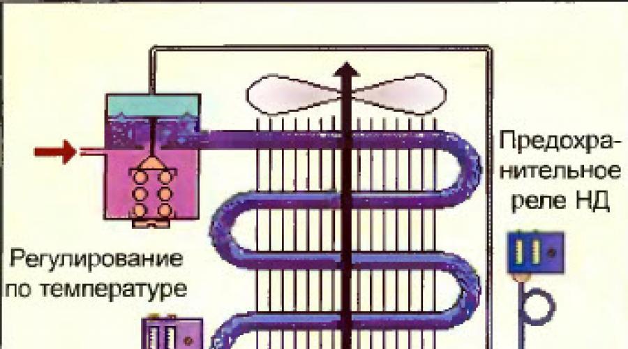
This property technology:
had two pre-
LP regulator
Pressure regulation
Rice. 45.1.
Firstly, it made it possible to do without a master thermostat, since the LP relay performed a dual function - a master and a safety relay.
Secondly, to ensure that the evaporator is defrosted at each cycle, it was enough to set the system so that the compressor starts at a pressure corresponding to a temperature above 0°C, and thus save on the defrost system!
However, when the compressor is stopped, in order for the evaporating pressure to exactly match the temperature in cold store required the constant presence of liquid in the evaporator. This is why, at that time, evaporators were fed very often from below and were always half-filled with liquid refrigerant (see Fig. 45.1).
These days, pressure regulation is rarely used, as it has the following negative points:
If the condenser is air-cooled (which is the most common case), the condensing pressure varies greatly throughout the year (see section 2.1. "Condensers with air-cooled. Normal operation "). These changes in the condensing pressure necessarily lead to changes in the evaporating pressure and therefore changes in the total temperature difference across the evaporator. Thus, the temperature in the refrigerator compartment cannot be kept stable and will be subject to large changes. Therefore, it is necessary either to use condensers with water cooling, or apply effective system condensing pressure stabilization.
If even slight anomalies occur in the operation of the plant (in terms of evaporating or condensing pressures), leading to a change in the total temperature difference across the evaporator, even a slight one, the temperature in the refrigeration chamber can no longer be maintained within the specified limits.

If the compressor discharge valve is not tight enough, when the compressor stops, the evaporating pressure rises rapidly and there is a danger of an increase in the frequency of compressor start-stop cycles.
This is why today the most commonly used cold room temperature sensor is used to shut down the compressor, and the LP switch only performs protection functions (see fig. 45.2).
Note that in this case the method of feeding the evaporator (from below or from above) has almost no noticeable effect on the quality of regulation.
B) The design of modern evaporators

With an increase in the cooling capacity of the evaporators, their dimensions, in particular the length of the tubes used for their manufacture, also increase.
So, in the example in Fig. 45.3, the designer must connect two sections of 0.5 kW each in series to obtain a performance of 1 kW.
But this technology is of limited use. Indeed, doubling the length of pipelines also doubles the pressure loss. That is, pressure losses in large evaporators quickly become too great.
Therefore, when increasing the power, the manufacturer no longer has separate sections in series, but connects them in parallel in order to keep pressure losses as low as possible.
However, this requires that each evaporator be supplied with exactly the same amount of liquid, and therefore the manufacturer installs a liquid distributor at the evaporator inlet.
3 evaporator sections connected in parallel
Rice. 45.3.
For such evaporators, the question of whether to feed them from below or from above is no longer worth it, since they are fed only through a special liquid distributor.
Now let's look at ways to specialize pipelines to different types evaporators.
To begin with, as an example, let's take a small evaporator, the small capacity of which does not require the use of a liquid distributor (see Fig. 45.4).
 The refrigerant enters the inlet of the evaporator E and then descends through the first section (bends 1, 2, 3). Then it rises in the second section (bends 4, 5, 6 and 7) and before leaving the evaporator at its outlet S, it again falls along the third section (bends 8, 9, 10 and 11). Note that the refrigerant falls, rises, then falls again, and moves towards the direction of movement of the cooled air.
Consider now an example of a more powerful evaporator, which has considerable size and powered by a liquid distributor.

Each share of the total refrigerant flow enters the inlet of its section E, rises in the first row, then descends in the second row and leaves the section through its outlet S (see Fig. 45.5).
In other words, the refrigerant rises and then falls in the pipes, always moving against the direction of the cooling air. So, whatever the type of evaporator, the refrigerant alternately lowers and rises.
Therefore, there is no concept of an evaporator read from above or below, especially for the most common case where the evaporator is fed through a liquid distributor.
On the other hand, in both cases, we saw that the air and the refrigerant move according to the countercurrent principle, that is, towards each other. It is useful to recall the reasons for choosing such a principle (see Figure 45.6).

Pos. 1: This evaporator is powered by an expansion valve which is set to provide 7K superheat. To ensure such overheating of the vapors leaving the evaporator, a certain section of the length of the evaporator pipeline, blown with warm air, serves.
Pos. 2: It's about about the same area, but with the direction of air movement coinciding with the direction of movement of the refrigerant. It can be stated that in this case the length of the section of the pipeline that provides vapor overheating increases, since it is blown with colder air than in the previous case. This means that the evaporator contains less liquid, hence the expansion valve is more blocked, i.e. the evaporating pressure is lower and the cooling capacity is lower (see also section 8.4. "Expansion valve exercise").
Pos. 3 and 4: Although the evaporator is fed from below, and not from above, as in pos. 1 and 2, the same phenomena are observed.
Thus, although most of the examples of direct expansion evaporators discussed in this manual are liquid-fed from above, this is done purely for simplicity and clarity. In practice, a refrigeration installer will almost never actually make a mistake in connecting a liquid distributor to an evaporator.
When in doubt, if the direction of air flow through the evaporator is not very clear, in order to choose the method of connecting the piping to the evaporator, strictly follow the designer's instructions in order to achieve the cooling capacity declared in the documentation for the evaporator.
→ Installation of refrigeration units
Installation of main devices and auxiliary equipment
To the main devices refrigeration unit include devices that are directly involved in mass and heat transfer processes: condensers, evaporators, subcoolers, air coolers, etc. Receivers, oil separators, dirt traps, air separators, pumps, fans and other equipment that is part of the refrigeration unit are classified as auxiliary equipment.
The installation technology is determined by the degree of factory readiness and design features of the devices, their weight and installation design. First, the main devices are installed, which allows you to start laying pipelines. To prevent moistening of the thermal insulation, a layer of waterproofing is applied to the supporting surface of apparatus operating at low temperatures, a thermal insulation layer is laid, and then a waterproofing layer is laid again. To create conditions that exclude the formation of thermal bridges, all metal parts (fastening belts) are placed on the apparatus through wooden antiseptic bars or spacers 100-250 mm thick.
Heat exchangers. Most of the heat exchangers are supplied by the factories ready for installation. So, shell-and-tube condensers, evaporators, subcoolers are supplied assembled, elemental, spray, evaporative condensers and panel, submersible evaporators- assembly units. Finned tube evaporators, direct expansion batteries and brine evaporators can be manufactured installation organization on site from sections of finned tubes.
Shell-and-tube devices (as well as capacitive equipment) are mounted in a flow-combined way. When laying welded machines on supports, make sure that all welds are available for inspection, tapping with a hammer during survey, and also for repair.
The horizontality and verticality of the devices are checked by level and plumb or with the help of geodetic instruments. Permissible deviations of the devices from the vertical are 0.2 mm, horizontally - 0.5 mm per 1 m. If the device has a collector or sump, a slope is only allowed in their direction. The verticality of shell-and-tube vertical condensers is especially carefully verified, since it is necessary to ensure the film runoff of water along the walls of the pipes.
Elemental capacitors (due to the high metal content they are used in rare cases in industrial plants) set to metal frame, above the receiver by elements from the bottom up, checking the horizontality of the elements, the one-planeness of the flanges of the fittings and the verticality of each section.
Installation of irrigation and evaporative condensers consists in serial installation sump, heat exchange tubes or coils, fans, oil separator, pump and fittings.
Air-cooled units used as condensers in refrigeration units are mounted on a pedestal. For centering axial fan relative to the guide vane, there are slots in the plate that allow you to move the gearbox plate in two directions. The fan motor is centered on the gearbox.
Panel brine evaporators are placed on an insulating layer, on a concrete pad. The metal tank of the evaporator is mounted on wooden bars, mount the agitator and brine valves, connect the drain pipe and test the tank for density by pouring water. The water level should not fall during the day. Then the water is drained, the bars are removed and the tank is lowered onto the base. Panel sections are tested with air at a pressure of 1.2 MPa before installation. Then, the sections are mounted in the tank in turn, collectors, fittings, a liquid separator are installed, the tank is filled with water and the evaporator assembly is again tested with air at a pressure of 1.2 MPa.

Rice. 1. Installation of horizontal condensers and receivers using the in-line method:
a, b - in a building under construction; c - on supports; g - on flyovers; I - the position of the capacitor in front of the slinging; II, III - positions when moving the crane boom; IV - installation on support structures

Rice. 2. Installation of capacitors:
0 - elemental: 1 - supporting metal structures; 2 - receiver; 3 - capacitor element; 4 - plumb line for checking the verticality of the section; 5 - level to check if the element is horizontal; 6 - ruler for checking the location of the flanges in the same plane; b - irrigation: 1 - water drain; 2 - pallet; 3 - receiver; 4 - sections of coils; 5 - supporting metal structures; 6 - water distribution trays; 7 - water supply; 8 - overflow funnel; c - evaporative: 1 - water collector; 2 - receiver; 3, 4 - level indicator; 5 - nozzles; 6 - drop eliminator; 7 - oil separator; 8 - safety valves; 9 - fans; 10 - precondenser; 11 - float water level regulator; 12 - overflow funnel; 13 - pump; g - air: 1 - supporting metal structures; 2 - drive frame; 3 - guide apparatus; 4 - section of ribbed heat exchange tubes; 5 - flanges for connecting sections to collectors
Immersion evaporators are mounted in this manner and pressure tested. inert gas 1.0 MPa for systems with R12 and 1.6 MPa for systems with R22.

Rice. 2. Mounting the panel brine evaporator:
a - testing the tank with water; b - testing of panel sections with air; c - installation of panel sections; d - test of the evaporator with water and air as an assembly; 1 - wooden bars; 2 - tank; 3 - mixer; 4 - panel section; 5 - goats; 6 - air supply ramp for testing; 7 - water drain; 8 - oil collector; 9-liquid separator; 10 - thermal insulation
Capacitive equipment and auxiliary devices. Linear ammonia receivers mounted on the side high pressure below the condenser (sometimes under it) on the same foundation, and the steam zones of the devices are connected by an equalizing line, which creates conditions for draining the liquid from the condenser by gravity. During installation, the difference in height marks from the liquid level in the condenser (the level of the outlet pipe from the vertical condenser) to the level of the liquid pipe from the overflow cup of the oil separator And is not less than 1500 mm (Fig. 25). Depending on the brands of the oil separator and the linear receiver, the differences in the height marks of the condenser, receiver and oil separator Yar, Yar, Nm and Ni, specified in the reference literature, are maintained.
On the low pressure side, drainage receivers are installed to drain ammonia from cooling devices when thawing a snow coat with hot ammonia vapors and protective receivers without pumping schemes to receive liquid in case of its release from the batteries with an increase in thermal load, as well as circulation receivers. Horizontal circulation receivers are mounted together with liquid separators placed above them. In vertical circulating receivers, the vapor is separated from the liquid in the receiver.

Rice. 3. Scheme of installation of the condenser, linear receiver, oil separator and air cooler in the ammonia refrigeration unit: KD - condenser; LR - linear receiver; HERE - air separator; SP - overflow glass; MO - oil separator
In refrigerant aggregated installations, linear receivers are installed above the condenser (without an equalizing line), and refrigerant enters the receiver in a pulsating flow as the condenser is filled.
All receivers are equipped with safety valves, pressure gauges, level indicators and shutoff valves.
Intermediate vessels are installed on supporting structures on wooden beams, taking into account the thickness of the thermal insulation.
cooling batteries. Direct-cooled freon batteries are supplied by manufacturers ready for installation. Brine and ammonia batteries are manufactured at the installation site. Brine batteries are made from steel electric-welded pipes. For the manufacture of ammonia batteries, steel seamless hot-rolled pipes (usually 38X3 mm in diameter) are used from steel 20 for operation at temperatures up to -40 ° C and from steel 10G2 for operation at temperatures up to -70 ° C.
Cold-rolled low-carbon steel strip is used for transverse-spiral finning of battery tubes. Pipes are finned on a semi-automatic equipment in the conditions of procurement workshops with a selective check with a probe of the fit of the fins to the pipe and the specified fin spacing (usually 20 or 30 mm). Finished pipe sections are hot-dip galvanized. In the manufacture of batteries, semi-automatic welding in a carbon dioxide environment or manual arc welding is used. Finned tubes are connected and the batteries are connected by collectors or coils. Collector, rack and coil batteries are assembled from unified sections.
After testing ammonia batteries with air for 5 minutes for strength (1.6 MPa) and for 15 minutes for density (1 MPa) of the place welded joints subjected to galvanizing with an electroplating gun.
Brine batteries are tested with water after installation at a pressure equal to 1.25 working pressure.
Batteries are attached to embedded parts or metal structures on ceilings (ceiling batteries) or on walls (wall batteries). Ceiling batteries are mounted at a distance of 200-300 mm from the axis of the pipes to the ceiling, wall batteries - at a distance of 130-150 mm from the axis of the pipes to the wall and at least 250 mm from the floor to the bottom of the pipe. When mounting ammonia batteries, the following tolerances are maintained: in height ± 10 mm, deviation from the verticality of wall-mounted batteries - no more than 1 mm per 1 m of height. When installing batteries, a slope of not more than 0.002 is allowed, and in the direction opposite to the movement of the refrigerant vapor. Wall-mounted batteries are mounted with cranes before the installation of floor slabs or with the help of loaders with an arrow. Ceiling batteries are mounted using winches through blocks attached to the ceilings.
Air coolers. They are installed on a pedestal (stand-mounted air coolers) or attached to embedded parts on ceilings (mounted air coolers).
Post-mounted air coolers are mounted by the flow-combined method using a jib crane. Before installation, insulation is laid on the pedestal and a hole is made for connecting a drainage pipeline, which is laid with a slope of at least 0.01 towards the drain into the sewer network. Mounted air coolers are mounted in the same way as ceiling batteries.

Rice. 4. Battery mounting:
a - batteries with an electric forklift; b - ceiling battery with winches; 1 - overlap; 2- embedded parts; 3 - block; 4 - slings; 5 - battery; 6 - winch; 7 - electric forklift
Cooling batteries and air coolers made of glass pipes. For the manufacture of coil-type brine batteries, glass pipes are used. Pipes are attached to racks only in straight sections (rolls are not fixed). The supporting metal structures of the batteries are attached to the walls or suspended from the ceilings. The distance between the posts should not exceed 2500 mm. Wall-mounted batteries to a height of 1.5 m are protected by mesh fences. The glass pipes of air coolers are mounted in a similar way.
For the manufacture of batteries and air coolers, pipes with smooth ends are taken, connecting them with flanges. After the installation is completed, the batteries are tested with water at a pressure equal to 1.25 working pressure.
Pumps. For pumping ammonia and other liquid refrigerants, refrigerants and chilled water, condensate, as well as for the release drainage wells and cooling water circulation use centrifugal pumps. To supply liquid refrigerants, only hermetically sealed glandless pumps of the XG type with an electric motor built into the pump housing are used. The stator of the electric motor is sealed, and the rotor is mounted on one shaft with impellers. The shaft bearings are cooled and lubricated by liquid refrigerant withdrawn from the discharge pipe and then transferred to the suction side. Sealed pumps are installed below the liquid intake point at a liquid temperature below -20 ° C (in order to prevent the pump from stalling, the suction pressure is 3.5 m).

Rice. 5. Installation and alignment of pumps and fans:
a - installation centrifugal pump along the logs with a winch; b - installation of a fan with a winch using braces
Before installing stuffing box pumps, check their completeness and, if necessary, carry out an audit.
Centrifugal pumps are installed on the foundation with a crane, a hoist, or along logs on rollers or a sheet of metal using a winch or levers. When installing the pump on a foundation with blind bolts embedded in its array, wooden beams are placed near the bolts so as not to jam the thread (Fig. 5, a). Check elevation, levelness, centering, presence of oil in the system, smoothness of rotation of the rotor and stuffing of the stuffing box (stuffing box). Stuffing box
The gland must be carefully stuffed and evenly bent without distortion. Excessive tightening of the stuffing box leads to its overheating and an increase in power consumption. When installing the pump above the receiving tank, a check valve is installed on the suction pipe.
Fans. Most fans are supplied as a unit ready for installation. After the fan is installed by a crane or a winch with guy wires (Fig. 5, b) on the foundation, pedestal or metal structures (through vibration isolating elements), the height and horizontality of the installation are verified (Fig. 5, c). Then they remove the rotor locking device, inspect the rotor and housing, make sure that there are no dents or other damage, manually check the smooth rotation of the rotor and the reliability of fastening all parts. Check the gap between the outer surface of the rotor and the housing (not more than 0.01 of the wheel diameter). Measure the radial and axial runout of the rotor. Depending on the size of the fan (its number), the maximum radial runout is 1.5-3 mm, axial runout is 2-5 mm. If the measurement shows an excess of tolerance, static balancing is carried out. The gaps between the rotating and fixed parts of the fan are also measured, which should be within 1 mm (Fig. 5, d).
During a trial run, within 10 minutes, the level of noise and vibration is checked, and after stopping, the reliability of fastening of all connections, the heating of the bearings and the condition of the oil system. The duration of the test under load is 4 hours, while checking the stability of the fan under operating conditions.
Installation of cooling towers. Small film-type cooling towers (I PV) are supplied for installation with a high degree factory readiness. The horizontal position of the cooling tower installation is verified, connected to the pipeline system, and after filling the water circulation system with softened water, the uniformity of irrigation of the nozzle from miplast or polyvinyl chloride plates is regulated by changing the position of the water spray nozzles.
When installing larger cooling towers after the construction of the pool and building structures install a fan, align its alignment with the cooling tower diffuser, adjust the position of the water distribution gutters or collectors and nozzles to evenly distribute water over the irrigation surface.

Rice. 6. Alignment of the impeller of the axial fan of the cooling tower with the guide vane:
a - by moving the frame relative to the supporting metal structures; b - cable tension: 1 - impeller hub; 2 - blades; 3 - guide apparatus; 4 - casing of the cooling tower; 5 - supporting metal structures; 6 - gearbox; 7 - electric motor; 8 - centering cables
Alignment is regulated by moving the frame and the electric motor in the grooves for the mounting bolts (Fig. 6, a), and in the largest fans, the alignment is achieved by adjusting the tension of the cables attached to the guide vane and supporting metal structures (Fig. 6, b). Then check the direction of rotation of the electric motor, smooth running, runout and vibration level at the operating speeds of rotation of the shaft.
In order to increase the safety of operation of the refrigeration plant, condensers, in-line receivers and oil separators (high-pressure apparatus) with large quantity coolant should be placed outside the engine room.
This equipment, as well as refrigerant storage receivers, must be surrounded by a metal barrier with a lockable entrance. The receivers must be protected by a canopy from sun rays and precipitation. Apparatus and vessels installed indoors can be located in the compressor shop or in a special control room if it has a separate exit to the outside. passage between smooth wall and the device must be at least 0.8 m, but it is allowed to install devices near walls without passages. The distance between the protruding parts of the apparatus must be at least 1.0 m, and if this passage is the main one - 1.5 m.
When mounting vessels and apparatuses on brackets or cantilever beams, the latter must be embedded in the main wall to a depth of at least 250 mm.
It is allowed to install devices on columns using clamps. It is forbidden to punch holes in columns for fixing equipment.
For installation of devices and further maintenance of condensers and circulation receivers, metal platforms with railing and stairs. With a platform length of more than 6 m, there should be two stairs.
Platforms and stairs must have handrails and rims. The height of the handrails is 1 m, the edges are not less than 0.15 m. The distance between the posts of the handrails is not more than 2 m.
Tests of devices, vessels and pipeline systems for strength and density are carried out upon completion installation work and within the time limits stipulated by the Rules for the Design and safe operation ammonia refrigeration units.
Horizontal cylindrical devices. Shell and tube evaporators, horizontal shell and tube condensers and horizontal receivers are installed on concrete foundations in the form of separate pedestals strictly horizontally with a permissible slope of 0.5 mm per 1 m of linear length towards the oil sump.
The devices rest on wooden antiseptic beams with a width of at least 200 mm with a recess in the shape of the body (Fig. 10 and 11) and are attached to the foundation with steel belts with rubber gaskets.

Low-temperature apparatuses are installed on bars with a thickness not less than the thickness of thermal insulation, and under
belts are placed wooden blocks 50-100 mm long and equal to the thickness of the insulation, at a distance of 250-300 mm from each other along the circumference (Fig. 11).
To clean the pipes of condensers and evaporators from contamination, the distance between their end caps and walls should be 0.8 m on one side and 1.5-2.0 m on the other. When installing devices in a room to replace the tubes of condensers and evaporators, a “false window” is arranged (in the wall opposite the cover of the device). To do this, an opening is left in the masonry of the building, which is filled heat-insulating material, sewn up with boards and plastered. When repairing devices, the “false window” is opened, and after the repair is completed, it is restored. Upon completion of work on the placement of devices, automation and control devices are mounted on them, stop valves, safety valves.
The cavity of the apparatus for the refrigerant is purged compressed air, the strength and density test is carried out with the covers removed. When mounting a capacitor-receiver unit, a horizontal shell-and-tube condenser is installed on the site above the linear receiver. The size of the site should provide a circular service of the apparatus.
Vertical shell-and-tube condensers. The devices are installed outdoors on a massive foundation with a pit for draining water. In the manufacture of the foundation, the bolts for fastening the lower flange of the apparatus are laid in concrete. Capacitor install crane on packs of linings and wedges. By tamping wedges, the apparatus is set strictly vertically with the help of plumb lines located in two mutually perpendicular planes. In order to prevent the swinging of plumb lines by the wind, their weights are lowered into a container with water or oil. Vertical arrangement apparatus is caused by the helical flow of water through its tubes. Even with a slight tilt of the apparatus, water will not normally wash the surface of the pipes. At the end of the alignment of the apparatus, the linings and wedges are welded into packages and the foundation is poured.
Evaporative condensers. Supplied for installation as an assembly and installed on a site, the dimensions of which allow for circular maintenance of these devices. ‘The height of the site is taken into account the placement of linear receivers under it. For ease of maintenance, the platform is equipped with a ladder, and if the fans are located on the top, it is additionally installed between the platform and the upper plane of the apparatus.
After installing the evaporative condenser, connect to it circulation pump and pipelines.

The most widespread are evaporative condensers of the TVKA and Evako types manufactured by VNR. The drop-breaker layer of these devices is made of plastic, therefore, in the area of installation of the devices, welding and other work with open flame. Fan motors are grounded. When installing the device on a hill (for example, on the roof of a building), it is necessary to use lightning protection.
Panel evaporators. Supplied as separate units, and their assembly is carried out during installation work.
The evaporator tank is tested for tightness by pouring water and installed on concrete slab 300-400 mm thick (Fig. 12), the height of the underground part of which is 100-150 mm. Between the foundation and the tank, wooden antiseptic beams or railway sleepers and thermal insulation are laid. Panel sections are installed in the tank strictly horizontally, according to the level. Side surfaces the tank is insulated and plastered, the mixer is adjusted.
Chamber devices. Wall and ceiling batteries are assembled from unified sections (Fig. 13) at the installation site.

For ammonia batteries, sections of pipes with a diameter of 38X2.5 mm are used, for a coolant - with a diameter of 38X3 mm. The pipes are finned with spirally wound ribs made of 1X45 mm steel tape with a rib spacing of 20 and 30 mm. The characteristics of the sections are presented in table. 6.

The total length of battery hoses in pump circuits should not exceed 100-200 m. The battery is installed in the chamber using embedded parts fixed in the ceiling during the construction of the building (Fig. 14).

Battery hoses are placed strictly horizontally in level.
Ceiling coolers are supplied for assembled installation. Bearing structures devices (channels) are connected to the channels of embedded parts. The horizontality of the installation of the apparatus is checked by the hydrostatic level.
Batteries and air coolers are lifted to the place of installation of the devices by loaders or other lifting devices. The permissible slope of the hoses must not exceed 0.5 mm per 1 m linear length.
To remove melt water during defrosting, drain pipes, on which heating elements of the ENGL-180 type are fixed. The heating element is a glass fiber tape, which is based on metal heating wires made of an alloy with a high resistivity. heating elements they are wound spirally onto the pipeline or laid linearly, fixing it on the pipeline with glass tape (for example, LES-0.2X20 tape). On the vertical section of the drain pipeline, heaters are installed only in a spiral. During linear laying, the heaters are fixed to the pipeline with glass tape in increments of not more than 0.5 m. After fixing the heaters, the pipeline is insulated non-combustible insulation and sheathed with a protective metal sheath. In places of significant bends of the heater (for example, on flanges), it is necessary to put an aluminum tape 0.2-1.0 mm thick and 40-80 mm wide under it to avoid local overheating.
At the end of the installation, all devices are tested for strength and density.
In the evaporator, the process of transition of the refrigerant from the liquid phase to the gaseous state occurs with the same pressure, the pressure inside the evaporator is the same everywhere. During the transition of a substance from liquid to gaseous (its boiling) in the evaporator, the evaporator absorbs heat, unlike the condenser, which releases heat into the environment. then. through two heat exchangers, the process of heat exchange takes place between two substances: the cooled substance, which is located around the evaporator, and the outside air, which is located around the condenser.

Scheme of the movement of liquid freon
Solenoid valve - shuts off or opens the refrigerant supply to the evaporator, always either fully open or fully closed (may not be present in the system)
A thermostatic expansion valve (TRV) is precision instrument, which regulates the supply of refrigerant to the evaporator depending on the intensity of the refrigerant boiling in the evaporator. It prevents liquid refrigerant from entering the compressor.
Liquid freon enters the expansion valve, the refrigerant is throttled through the membrane in the expansion valve (the freon is sprayed) and begins to boil due to the pressure drop, gradually the drops turn into gas throughout the entire section of the evaporator pipeline. Starting from the throttling device of the expansion valve, the pressure remains constant. Freon continues to boil and in a certain area of the evaporator completely turns into gas and then, passing through the evaporator, the gas begins to heat up with the air that is in the chamber.
If, for example, the boiling point of freon is -10 °С, the temperature in the chamber is +2 °С, freon, having turned into a gas in the evaporator, begins to heat up and at the outlet of the evaporator its temperature should be equal to -3, -4 °С, thus Δt ( the difference between the boiling point of the refrigerant and the temperature of the gas at the outlet of the evaporator) should be = 7-8, this is the mode normal operation systems. With a given Δt, we will know that there will be no particles of unboiled freon at the outlet of the evaporator (they should not be), if boiling occurs in the pipe, then not all power is used to cool the substance. The pipe is thermally insulated so that the freon does not heat up to a temperature environment, because The refrigerant gas cools the compressor stator. If, nevertheless, liquid freon enters the pipe, it means that the dose of its supply to the system is too large, or the evaporator is set to a weak (short) one.
If Δt is less than 7, then the evaporator is filled with freon, it does not have time to boil away and the system does not work properly, the compressor is also filled with liquid freon and fails. AT big side overheating is not as dangerous as overheating to a lower side, at Δt ˃ 7 the compressor stator may overheat, but a slight excess of overheating may not be felt by the compressor and it is preferable during operation.
With the help of fans located in the air cooler, the cold is removed from the evaporator. If this did not happen, then the tubes would be covered with ice and at the same time the refrigerant would reach its saturation temperature, at which it ceases to boil, and then, even regardless of the pressure drop, liquid freon would enter the evaporator without evaporating, filling the compressor.