DIY modular power supply. Do it yourself - mini portable laboratory power supply from Chinese LM2596 modules! it can hardly be called a stabilizer
Read also
Today, ready-made switching voltage stabilizer modules based on the LM2596 chip have become available.
Quite high parameters are declared, and the cost of the finished module is less than the cost of the parts included in it. The small size of the board is attractive.
I decided to purchase a few and test them out. I hope my experience will be useful to less experienced radio amateurs.
I bought modules on ebay, as in the photo above. Although the website showed 50V solid capacitors, the auction lived up to its name. The capacitors are ordinary, and half of the modules have capacitors for a voltage of 16 V.
...it can hardly be called a stabilizer...
You might think that it is enough to take a transformer, a diode bridge, connect a module to them, and we have a stabilizer with an output voltage of 3...30 V and a current of up to 2 A (short-term up to 3 A).That's exactly what I did. Without load everything was fine. A transformer with two windings of 18 V and a promised current of up to 1.5 A (the wire was clearly too thin by eye, and so it turned out).
I needed a +-18 V stabilizer and I set the required voltage.
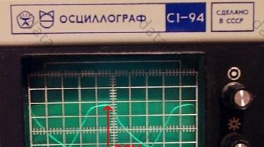
With a 12 Ohm load the current is 1.5 A, here is the waveform, 5 V/cell vertical.
It can hardly be called a stabilizer.
The reason is simple and clear: the capacitor on the board is 200 uF, it serves only for normal operation DC-DC converter. When voltage was applied to the input from a laboratory power supply, everything was fine. The solution is obvious: you need to power the stabilizer from a source with low ripples, i.e. add a capacitance after the bridge.
Here is the voltage with a load of 1.5 A at the input of the module without an additional capacitor.

With an additional 4700 uF capacitor at the input, the output ripple decreased sharply, but at 1.5 A it was still noticeable. When reducing the output voltage to 16V, the ideal straight line (2V/cell).

The voltage drop across the DC-DC module must be at least 2…2.5 V.
Now you can watch the ripples at the output of the pulse converter.

Small pulsations with a frequency of 100 Hz modulated with a frequency of several tens of kHz are visible. The Datasheet on the 2596 recommends an additional LC filter on the output. That's what we'll do. As a core, I used a cylindrical core from a faulty computer power supply and wound the winding in two layers with 0.8 mm wire.

The board shows in red the place for installing a jumper - the common wire of two channels; the arrow shows the place for soldering the common wire, if you do not use terminals.
Let's see what happened to the HF pulsations.

They are no longer there. Small pulsations with a frequency of 100 Hz remained.
Not ideal, but not bad.
I note that as the output voltage increases, the inductor in the module begins to rattle and RF interference at the output sharply increases; as soon as the voltage is slightly reduced (all this with a load of 12 ohms), the interference and noise completely disappear.
To mount the module, I used homemade “stands” made of tinned wire with a diameter of 1 mm.

This provided convenient installation and cooling of modules. The posts can get very hot when soldering and will not move like simple pins. The same design is convenient if you need to solder external wires to the board - good rigidity and contact.
The board makes it easy to replace the DC-DC module if necessary.
General view of the board with chokes from halves of some kind of ferrite core (inductance is not critical).

Final circuit diagram:
The scheme is simple and obvious.With a long-term load of 1 A current, the parts heat up noticeably: the diode bridge, the microcircuit, the module choke, most of all the choke (additional chokes are cold). Heating to the touch is 50 degrees.
When operating from a laboratory power supply, heating at currents of 1.5 and 2 A is tolerable for several minutes. For long-term operation with high currents, a heat sink to the microcircuit and a larger inductor is desirable.
Despite the tiny size of the DC-DC module, general dimensions The boards turned out to be comparable to the analog stabilizer board.

Conclusions:
1. A transformer with a high-current secondary winding or with a voltage reserve is required; in this case, the load current may exceed the current of the transformer winding.2. At currents of the order of 2 A or more, a small heat sink to the diode bridge and the 2596 microcircuit is desirable.
3. It is desirable to have a large capacity power capacitor, this has a beneficial effect on the operation of the stabilizer. Even a large and high-quality container heats up a little, therefore a low ESR is desirable.
4. To suppress ripple with the conversion frequency, an LC filter at the output is required.
5. This stabilizer has a clear advantage over a conventional compensation one in that it can operate in a wide range of output voltages; at low voltages, it is possible to obtain an output current greater than what the transformer can provide.
6. The modules allow you to make a power supply with good parameters simply and quickly, bypassing the pitfalls of making boards for pulse devices, that is, good for beginner radio amateurs.
I have already done a couple of reviews of a similar thing (see photo). I ordered those devices not for myself, but for friends. A convenient device for homemade charging, and more. I was jealous too and decided to order it for myself. I ordered not only a volt-ampermeter, but also the cheapest voltmeter. I decided to assemble a power supply for my homemade products. I decided which one to put only after I had assembled the product completely. Surely there will be people who are interested.
Ordered on November 11th. There was a small discount. Although the price is low.
The parcel arrived for more than two months. The seller gave the left track from Wedo Express. But still the parcel arrived and everything works. Formally, there are no complaints.
Since I decided to integrate this particular device into my power supply, I’ll tell you a little more about it.
The device arrived as standard plastic bag, “bulging” from the inside. 
IN this moment product unavailable. But this is not critical. There are now a lot of offers on Ali from sellers with good rating. Moreover, the price is steadily decreasing.
The device was additionally sealed in an antistatic bag. 
Inside is the device itself and wires with connectors. 
Keyed connectors. Don't insert it the other way around. 
The sizes are simply miniature. 
Let's look at what is written on the seller's page. 
My translation with corrections:
-Measured voltage: 0-100V
- Circuit supply voltage: 4.5-30V
-Minimum Resolution (V): 0.01V
-Current consumption: 15mA
-Measured current: 0.03-10A
-Minimum resolution (A): 0.01A
Everything is the same, but very briefly, on the side of the product. 
I immediately took it apart and noticed that minor parts were missing. 
But in previous modules this place was occupied by a capacitor. 
But their prices also differed to a greater extent.
All modules are similar like twins. There is also connection experience. The small connector is designed to power the circuit. By the way, at a voltage below 4V, the blue indicator becomes almost invisible. Therefore we follow technical specifications devices, we do not supply less than 4.5V. If you want to use this device to measure voltages below 4V, you need to power the circuit from a separate source through a “fine wire connector”.
The current consumption of the device is 15mA (when powered by a 9V crown).
The connector with three thick wires is a measuring one. 
There are two accuracy controls (IR and VR). Everything is clear in the photo. Resistors are ugly. Therefore, I don’t recommend twisting it often (you’ll break it). Red wires are terminals for voltage, blue for current, black wires are “common” (connected to each other). The colors of the wires correspond to the color of the indicator, so you won’t get confused.
Head chip without name. It once existed, but it was destroyed. 
Now I’ll check the accuracy of the readings using the P320 model setup. I applied calibrated voltages 2V, 5V, 10V, 12V 20V, 30V to the input. Initially, the device underestimated by one tenth of a volt within certain limits. The error is insignificant. But I adjusted it to suit myself. 
It can be seen that it shows almost perfectly. I adjusted it with the right resistor (VR). When rotating the trimmer clockwise, it adds, and when rotating counterclockwise, it decreases the readings.
Now I'll see how it measures current strength. I power the circuit from 9V (separately) and supply a reference current from the P321 installation 
The minimum threshold from which a current of 30mA begins to be correctly measured.
As you can see, it measures the current quite accurately, so I won’t twist the adjustment resistor. The device measures correctly even at currents greater than 10A, but the shunt begins to heat up. Most likely, the current limitation is for this reason. 
I also don’t recommend driving for a long time at a current of 10A.
I compiled more detailed calibration results into a table. 
I liked the device. But there are disadvantages.
1.The inscriptions V and A are painted, so they will not be visible in the dark.
2.The device measures current in one direction only.
I would like to draw your attention to the fact that seemingly the same devices, but from different sellers, can be fundamentally different from each other. Be careful.
Sellers often publish incorrect connection diagrams on their pages. IN in this case no complaints. I just changed it (the diagram) a little to make it more understandable to the eye. 
With this device, in my opinion, everything is clear. Now I’ll tell you about the second device, about the voltmeter.
I ordered on the same day, but from a different seller:
Bought for US $1.19. Even at today's exchange rate, it's ridiculous money. Since I didn’t end up installing this device, I’ll go over it briefly. With the same dimensions, the numbers are much larger, which is natural. 
This device does not have a single tuning element. Therefore, it can only be used in the form in which it was sent. Let's hope for Chinese good faith. But I'll check.
The installation is the same P320. 
More details in table form. 
Although this voltmeter turned out to be several times cheaper than a voltammeter, its functionality did not suit me. It does not measure current. And the supply voltage is combined with the measuring circuits. Therefore, it does not measure below 2.6V.
Both devices have exactly the same dimensions. Therefore, replacing one with the other in your homemade product is a matter of minutes. 
I decided to build a power supply using a more universal voltammeter. The devices are inexpensive. There is no burden on the budget. The voltmeter will be in storage for now. The main thing is that the device is good, and there will always be a use for it. I just pulled out the missing components for the power supply from the storage room.
I’ve had this homemade set lying around idle for several years now. 
The scheme is simple but reliable. 
It’s pointless to check the completeness, a lot of time has passed, it’s too late to make a claim. But everything seems to be in place. 
The trimmer resistor (included) is too weak. I don't see any point in using it. Everything else will do.
I know all the shortcomings of linear stabilizers. I have neither the time, nor the desire, nor the opportunity to create something more worthy. If you need a more powerful power supply with high efficiency, then I’ll think about it. In the meantime, it will be what I did.
First I soldered the stabilizer board.
At work I found a suitable building.
I rewound the secondary of the toroidal trance to 25V. 
I selected a powerful radiator for the transistor. I put all this into the case.
But one of the most important elements circuit is a variable resistor. I took a multi-turn type SP5-39B. The output voltage accuracy is the highest. 
This is what happened. 
A little unsightly, but the main task is completed. I protected all the electrical parts from myself, I also protected myself from the electrical parts :)
Just a little bit of retouching left. I'll spray paint the case and make the front panel more attractive.
That's all. Good luck!
In this article I want to tell and show in the photo my laboratory power supply, which I assembled block by block, on ready-made modules from Aliexpress. I have already talked about these same modules separately on the site. I wanted to make a simple, reliable, affordable unit, with the necessary parameters and small dimensions. I watched a couple of videos about similar blocks on the Internet, ordered the necessary modules and assembled them myself. Initially, a converted computer power supply was used as a power source. But since I still couldn’t get it to work properly (it got quite hot and fell a little short of the calculated maximum current), I decided to buy it from Aliexpress. Maximum operating voltage for the unit in most cases, 0-30 Volts is sufficient, although there was an idea to make from 0 to 50 Volts. The power source that I used delivers 36 Volts and a current of up to 5 Amperes. A power of 180 watts is quite enough for my tasks. I used it as a voltage and current regulator (limitation). The module acts as an indicator. A regular plastic housing of type Z1 (70x188x197 mm) was used as the housing. In principle, these modules are already enough to build a laboratory, but I added one more here in order to output 5 Volts to the USB connectors located on the front panel. We also, of course, need a pair of remote variable 10K resistors, a toggle switch to turn the power on/off, a pair of USB sockets (I took a double socket), and a pair of banana sockets for connecting the output cable. We fasten the modules inside the case, mark and drill the front panel.


Then we unsolder both trimming resistors from the module and solder in their place variable resistors on wires of sufficient length (I put another 1 K in series with the 10 K resistors for fine tuning, but this did not give much effect). Well, then we connect all the modules according to the diagram.


If you do it with USB, then do not forget to set the LM2596 module to 5V. And please note that the negative USB power cable is taken not from the LM2596 module, but from the output ground of the power supply unit (from the negative “banana”). This is necessary so that when you connect something to the USB block, you can see the current consumed. In my block you can see another module in the photo - this is also DC-DC, I wanted to leave it instead of LM2596 for the role of USB power, but it is quite power-hungry in idle mode, so I left the LM module. I also have a fan. If you also want to equip the unit with a fan, then select one that is suitable in size and for a voltage of 5 V. It is connected to the plus and minus of the LM2596 module (in this case, the minus is taken from the module, otherwise the current consumed by the fan will be constantly displayed on the indicator). I highly recommend that you turn it on for the first time through a 40-60 W incandescent lamp. If something is wrong, in this case you will avoid fireworks. My unit worked immediately, and so far there have been no problems with it.


I watch a lot of videos on repairing various electronics and often the video begins with the phrase “connect the board to the LBP and...”.
In general, the LPS is a useful and cool thing, it just costs like an airplane wing, and I don’t need precision of a fraction of a millivolt for crafts, it’s enough to replace a bunch of Chinese power supplies of dubious quality, and be able to determine how much power the device needs without fear of burning something lost power supply, connect and increase the voltage until it works (Routers, switches, laptops), and the so-called “Fault finding using the LBP method” is also a convenient thing (this is when there is a short circuit on the board, but which of the thousands SMD elements it's broken, you'll understand, a LBP with a current limit of 1A is attached to the inputs and a hot element is looked for by touch - heating = breakdown).
But because of the toad, I couldn’t afford such a luxury, but while crawling around Pikabu I came across an interesting post in which it is written how to assemble the power supply of your dreams from shit and sticks of Chinese modules.
Having delved further into this topic, I found a bunch of videos on how to assemble such a miracle Once Two.
Anyone can assemble such a craft, and the cost is not that expensive compared to ready-made solutions.
By the way, there is a whole album where people show off their crafts.
I ordered everything and began to wait.
The basis was a 24V 6A switching power supply (the same as in the soldering station, but more about that next time) 
Voltage and current regulation will go through such a converter - a limiter. 
Well, the indicator is up to 100 volts. 
In principle, this is enough for the circuit to work, but I decided to make a full-fledged device and bought more:
Power connectors for figure-of-eight cable

Banana connectors on the front panel and 10K multi-turn resistors for smooth adjustment.
I also found drills, bolts, nuts, hot glue at the nearest construction store and tore out a CD drive from an old system unit.
To begin with, I assembled everything on the table and tested it, the circuit is not complicated, I took it


I know that these are screenshots from YouTube, but I’m too lazy to download the video and cut out frames from there, the essence won’t change, but I couldn’t find the source of the pictures right now.
The pinout of my indicator was found on Google. 
I assembled and connected the light bulb for the load, it works, it needs to be assembled into a case, I have an old CD drive as the case (probably still working, but I think it’s time for this standard to retire) the drive is old, because the metal is thick and durable, the front panels are made of plugs from the system manager.
I figured out what would go where in the case, and the assembly began. 
I marked out the locations for the components, drilled holes, painted the canister frame and inserted the bolts. 
Under all the elements I glued plastic from the packaging of the headphones to avoid a possible short circuit on the case, and under the DC-DC converters for USB power and cooling I also put a thermal pad (having made a cutout in the plastic under it, having previously cut off all the protruding legs, I took the thermal pad itself from the drive, it cooled the motor driver).
I screwed one nut on from the inside and cut a washer from a plastic container on top to lift the palts above the body. 
I soldered all the wires because there is no faith in the clamps, they might become loose and start to heat up. 


To blow through the hottest elements (voltage regulator) set to side wall 2 40mm 12V fans, since the power supply does not heat up all the time, but only under load, I don’t really want to constantly listen to the howling of not the quietest fans (yes, I took the cheapest fans, and they make a lot of noise) to control the cooling I ordered this temperature control module, a thing simple and super useful, you can both cool and heat, it’s easy to set up. Here are the instructions. 
I set it to about 40 degrees, and the heatsink of the converter was the hottest point.

In order not to drive excess air, I set the cooling power converter to about 8 volts.
In the end, we got something like this, there’s a lot of space inside, and you can add some kind of load resistor.

Already for the final look I ordered twisters, I had to cut off 5mm of the resistor shaft and put 2 plastic washers with inside so that the handles are close to the body. 

And we have a completely suitable power supply, with an additional USB output that can provide 3A for charging the tablet.
This is what the power supply looks like with rubber feet (3M Bumpon Self-adhesive) paired with a soldering station.


I am pleased with the result; it turned out to be quite a powerful power supply with smooth adjustment and at the same time time is easy and portable, I sometimes work on the road and carry around a factory LBP with toroidal transformer Not a thrill at all, but here it fits quite easily into a backpack.
I’ll tell you how I made the soldering station next time.
Many already know that I have a weakness for all kinds of power supplies, but here is a two-in-one review. This time there will be a review of a radio constructor that allows you to assemble the basis for a laboratory power supply and a variant of its real implementation.
I warn you, there will be a lot of photos and text, so stock up on coffee :)
First, I’ll explain a little what it is and why.
Almost all radio amateurs use such a thing as a laboratory power supply in their work. Whether it's complicated with program controlled or very simple on LM317, but it still does almost the same thing, powers different loads while working with them.
Laboratory power supplies are divided into three main types.
With pulse stabilization.
With linear stabilization
Hybrid.
The first ones include a switching controlled power supply, or simply a switching power supply with a step-down PWM converter. I have already reviewed several options for these power supplies. , .
Advantages - high power with small dimensions, excellent efficiency.
Disadvantages - RF ripple, presence of capacious capacitors at the output
The latter do not have any PWM converters on board, all adjustment is carried out in a linear way, where excess energy is simply dissipated on the control element.
Pros - Almost complete absence of ripple, no need for output capacitors (almost).
Cons - efficiency, weight, size.
The third is a combination of either the first type with the second, then the linear stabilizer is powered by a slave buck PWM converter (the voltage at the output of the PWM converter is always maintained at a level slightly higher than the output, the rest is regulated by a transistor operating in linear mode.
Or it is a linear power supply, but the transformer has several windings that switch as needed, thereby reducing losses on the control element.
This scheme has only one drawback, complexity, which is higher than that of the first two options.
Today we will talk about the second type of power supply, with a regulating element operating in linear mode. But let's look at this power supply using the example of a designer, it seems to me that this should be even more interesting. After all, in my opinion this a good start for a beginner radio amateur, assemble one of the main devices.
Well, or as they say, correct block food must be heavy :)
This review is more aimed at beginners; experienced comrades are unlikely to find anything useful in it.
For review, I ordered a construction kit that allows you to assemble the main part of a laboratory power supply.
The main characteristics are as follows (from those declared by the store):
Input voltage - 24 Volts alternating current
Output voltage adjustable - 0-30 Volts direct current.
Output current adjustable - 2mA - 3A
Output voltage ripple - 0.01%
The dimensions of the printed board are 80x80mm.
A little about packaging.
The designer arrived in a regular plastic bag, wrapped in soft material.
Inside, in an antistatic zip-lock bag, were all the necessary components, including the circuit board. 
Everything inside was a mess, but nothing was damaged, printed circuit board partially protected radio components. 
I won’t list everything that is included in the kit, it’s easier to do this later during the review, I’ll just say that I had enough of everything, even some left over. 
A little about the printed circuit board.
The quality is excellent, the circuit is not included in the kit, but all the ratings are marked on the board.
The board is double-sided, covered with a protective mask. 
The board coating, tinning, and the quality of the PCB itself is excellent.
I was only able to tear off a patch from the seal in one place, and that was after I tried to solder a non-original part (why, more to come).
In my opinion, this is the best thing for a beginner radio amateur; it will be difficult to spoil it. 
Before installation, I drew a diagram of this power supply. 
The scheme is quite thoughtful, although not without its shortcomings, but I’ll tell you about them in the process.
Several main nodes are visible in the diagram; I separated them by color.
Green - voltage regulation and stabilization unit
Red - current regulation and stabilization unit
Purple - indicating unit for switching to current stabilization mode
Blue - reference voltage source.
Separately there are:
1. Input diode bridge and filter capacitor
2. Power control unit on transistors VT1 and VT2.
3. Protection on transistor VT3, turning off the output until the power supply to the operational amplifiers is normal
4. Fan power stabilizer, built on a 7824 chip.
5. R16, R19, C6, C7, VD3, VD4, VD5, unit for forming the negative pole of the power supply of operational amplifiers. Due to the presence of this unit, the power supply will not operate simply on direct current; it is the alternating current input from the transformer that is required.
6. C9 output capacitor, VD9, output protective diode. 
First, I will describe the advantages and disadvantages of the circuit solution.
Pros -
It's nice to have a stabilizer to power the fan, but the fan needs 24 Volts.
I am very pleased with the presence of a power source of negative polarity; this greatly improves the operation of the power supply at currents and voltages close to zero.
Due to the presence of a source of negative polarity, protection was introduced into the circuit; as long as there is no voltage, the power supply output will be turned off.
The power supply contains a reference voltage source of 5.1 Volts, this made it possible not only to correctly regulate the output voltage and current (with this circuit, voltage and current are regulated from zero to maximum linearly, without “humps” and “dips” at extreme values), but also makes it possible to control external power supply, I simply change the control voltage.
The output capacitor has a very small capacitance, which allows you to safely test the LEDs; there will be no current surge until the output capacitor is discharged and the PSU enters current stabilization mode.
The output diode is necessary to protect the power supply from supplying reverse polarity voltage to its output. True, the diode is too weak, it is better to replace it with another one.
Minuses.
The current-measuring shunt has too high a resistance, because of this, when operating with a load current of 3 Amps, about 4.5 Watts of heat are generated on it. The resistor is designed for 5 Watts, but the heating is very high.
The input diode bridge is made up of 3 Ampere diodes. It’s good to have at least 5 Ampere diodes, since the current through the diodes in such a circuit is equal to 1.4 of the output, so in operation the current through them can be 4.2 Amperes, and the diodes themselves are designed for 3 Amperes. The only thing that makes the situation easier is that the pairs of diodes in the bridge work alternately, but this is still not entirely correct.
The big minus is that Chinese engineers, when selecting operational amplifiers, chose op-amps with maximum voltage at 36 Volts, but did not think that the circuit has a negative voltage source and the input voltage in this version is limited at 31 Volts (36-5 = 31). With an input of 24 Volts AC, DC will be about 32-33 Volts.
Those. The op amps will operate in extreme mode (36 is the maximum, standard 30).
I'll talk more about the pros and cons, as well as about upgrading later, but now I'll move on to the actual assembly.
First, let's lay out everything that is included in the kit. This will make assembly easier, and it will simply be clearer to see what has already been installed and what remains. 
I recommend starting the assembly with the lowest elements, since if you install the high ones first, then it will be inconvenient to install the low ones later.
It is also better to start by installing those components that are more of the same.
I'll start with resistors, and these will be 10 kOhm resistors.
The resistors are high quality and have an accuracy of 1%.
A few words about resistors. Resistors are color coded. Many may find this inconvenient. In fact, this is better than alphanumeric markings, since the markings are visible in any position of the resistor.
Don't be scared color coding, on initial stage you can use it, and over time it will be possible to determine it without it.
For understanding and convenient work With such components, you just need to remember two things that will be useful to a novice radio amateur in life.
1. Ten basic marking colors
2. Series values, they are not very useful when working with precision resistors of the E48 and E96 series, but such resistors are much less common.
Any radio amateur with experience will list them simply from memory.
1, 1.1, 1.2, 1.3, 1.5, 1.6, 1.8, 2, 2.2, 2.4, 2.7, 3, 3.3, 3.6, 3.9, 4.3, 4.7, 5.1, 5.6, 6.2, 6.8, 7.5, 8.2, 9.1.
All other denominations are multiplied by 10, 100, etc. For example 22k, 360k, 39Ohm.
What does this information provide?
And it gives that if the resistor is of the E24 series, then, for example, a combination of colors -
Blue + green + yellow is impossible in it.
Blue - 6
Green - 5
Yellow - x10000
those. According to calculations, it comes out to 650k, but there is no such value in the E24 series, there is either 620 or 680, which means either the color was recognized incorrectly, or the color has been changed, or the resistor is not in the E24 series, but the latter is rare.
Okay, enough theory, let's move on.
Before installation, I shape the resistor leads, usually using tweezers, but some people use a small homemade device for this.
We are not in a hurry to throw away the cuttings of the leads; sometimes they can be useful for jumpers. 
Having established the main quantity, I reached single resistors.
It may be more difficult here; you will have to deal with denominations more often. 
I don’t solder the components right away, but simply bite them and bend the leads, and I bite them first and then bend them.
This is done very easily, the board is held in your left hand (if you are right-handed), and the component being installed is pressed at the same time.
IN right hand There are side cutters, we bite off the leads (sometimes even several components at once), and immediately bend the leads with the side edge of the side cutters.
This is all done very quickly, after a while it is already automatic. 
Now we’ve reached the last small resistor, the value of the required one and what’s left are the same, that’s not bad :) 
Having installed the resistors, we move on to diodes and zener diodes.
There are four small diodes here, these are the popular 4148, two zener diodes of 5.1 Volts each, so it’s very difficult to get confused.
We also use it to form conclusions. 
On the board, the cathode is indicated by a stripe, just like on diodes and zener diodes. 
Although the board has a protective mask, I still recommend bending the leads so that they do not fall on adjacent tracks; in the photo, the diode lead is bent away from the track. 
The zener diodes on the board are also marked as 5V1. 
There are not very many ceramic capacitors in the circuit, but their markings can confuse a novice radio amateur. By the way, it also obeys the E24 series.
The first two digits are the nominal value in picofarads.
The third digit is the number of zeros that must be added to the denomination
Those. for example 331 = 330pF
101 - 100pF
104 - 100000pF or 100nF or 0.1uF
224 - 220000pF or 220nF or 0.22uF 
The main number of passive elements has been installed. 
After that, we move on to installing operational amplifiers.
I would probably recommend buying sockets for them, but I soldered them as is.
On the board, as well as on the chip itself, the first pin is marked.
The remaining conclusions are counted counterclockwise.
The photo shows the place for the operational amplifier and how it should be installed. 
For microcircuits, I do not bend all the pins, but only a couple, usually these are the outer pins diagonally.
Well, it’s better to bite them so that they stick out about 1mm above the board. 
That's it, now you can move on to soldering.
I use a very ordinary soldering iron with temperature control, but a regular soldering iron with a power of about 25-30 watts is quite sufficient.
Solder 1mm in diameter with flux. I specifically do not indicate the brand of solder, since the solder on the coil is not original (original coils weigh 1Kg), and few people will be familiar with its name. 
As I wrote above, the board is of high quality, soldered very easily, I did not use any fluxes, only what is in the solder is enough, you just need to remember to sometimes shake off the excess flux from the tip. 

Here I took a photo with an example of good soldering and not so good one.
A good solder should look like a small droplet enveloping the terminal.
But there are a couple of places in the photo where there is clearly not enough solder. This will happen on a double-sided board with metallization (where the solder also flows into the hole), but this cannot be done on a single-sided board; over time, such soldering may “fall off”. 
The terminals of the transistors also need to be pre-formed; this must be done in such a way that the terminal does not become deformed near the base of the case (elders will remember the legendary KT315, whose terminals loved to break off).
I shape powerful components a little differently. Molding is done so that the component stands above the board, in which case less heat will transfer to the board and will not destroy it. 
This is what molded powerful resistors look like on a board.
All components were soldered only from below, the solder that you see on the top of the board penetrated through the hole due to capillary effect. It is advisable to solder so that the solder penetrates a little to the top, this will increase the reliability of the soldering, and in the case of heavy components, their better stability. 
If before this I molded the terminals of the components using tweezers, then for the diodes you will already need small pliers with narrow jaws.
The conclusions are formed in approximately the same way as for resistors. 
But there are differences during installation.
If for components with thin leads installation occurs first, then biting, then for diodes the opposite is true. You simply won’t bend such a terminal after biting it, so first we bend the terminal, then bite off the excess. 
The power unit is assembled using two transistors connected according to a Darlington circuit.
One of the transistors is installed on a small radiator, preferably through thermal paste.
The kit included four M3 screws, one goes here. 
A couple of photos of the nearly soldered board. I won’t describe the installation of the terminal blocks and other components; it’s intuitive and can be seen from the photograph.
By the way, about the terminal blocks, the board has terminal blocks for connecting the input, output, and fan power. 

I haven't washed the board yet, although I often do it at this stage.
This is due to the fact that there will still be a small part to finalize. 
After the main assembly stage we are left with the following components.
Powerful transistor
Two variable resistors
Two connectors for board installation
Two connectors with wires, by the way the wires are very soft, but of small cross-section.
Three screws. 
Initially, the manufacturer intended to place variable resistors on the board itself, but they are placed so inconveniently that I didn’t even bother to solder them and showed them just as an example.
They are very close and it will be extremely inconvenient to adjust, although it is possible. 
But thank you for not forgetting to include the wires with connectors, it’s much more convenient.
In this form, the resistors can be placed on the front panel of the device, and the board can be installed in a convenient place.
At the same time, I soldered a powerful transistor. This is normal bipolar transistor, but having a maximum power dissipation of up to 100 Watts (naturally when installed on a radiator).
There are three screws left, I don’t even understand where to use them, if in the corners of the board, then four are needed, if you are attaching a powerful transistor, then they are short, in general it’s a mystery. 
The board can be powered from any transformer with an output voltage of up to 22 Volts (the specifications state 24, but I explained above why such a voltage cannot be used).
I decided to use a transformer that had been lying around for a long time for the Romantic amplifier. Why for, and not from, and because it hasn’t stood anywhere yet :)
This transformer has two output power windings of 21 Volts, two auxiliary windings of 16 Volts and a shield winding.
The voltage is indicated for the input 220, but since we now already have a standard of 230, the output voltages will be slightly higher.
The calculated power of the transformer is about 100 watts.
I parallelized the output power windings to get more current. Of course, it was possible to use a rectification circuit with two diodes, but it would not work better, so I left it as is. 
For those who don’t know how to determine the power of a transformer, I made a short video.
First trial run. I installed a small radiator on the transistor, but even in this form it was quite high heating, since the power supply is linear.
Adjustment of current and voltage occurs without problems, everything worked right away, so I can already fully recommend this designer.
The first photo is voltage stabilization, the second is current. 
First, I checked what the transformer outputs after rectification, as this determines the maximum output voltage.
I got about 25 Volts, not a lot. The capacity of the filter capacitor is 3300 μF, I would advise increasing it, but even in this form the device is quite functional. 
Since for further testing it was necessary to use a normal radiator, I moved on to assembling the entire future design, since the installation of the radiator depended on the intended design.
I decided to use the Igloo7200 radiator I had lying around. According to the manufacturer, such a radiator is capable of dissipating up to 90 watts of heat. 
The device will use a Z2A housing based on a Polish-made idea, the price will be about $3. 
Initially, I wanted to move away from the case that my readers are tired of, in which I collect all sorts of electronic things.
To do this, I chose a slightly smaller case and bought a fan with a mesh for it, but I couldn’t fit all the stuffing into it, so I purchased a second case and, accordingly, a second fan.
In both cases I bought Sunon fans, I really like the products of this company, and in both cases I bought 24 Volt fans. 
This is how I planned to install the radiator, board and transformer. There is even a little room left for the filling to expand.
There was no way to get the fan inside, so it was decided to place it outside. 
We mark the mounting holes, cut the threads, and screw them for fitting. 
Since the selected case has internal height 80mm, and the board also has this size, then I fixed the radiator so that the board is symmetrical with respect to the radiator. 
The leads of the powerful transistor also need to be slightly molded so that they do not become deformed when the transistor is pressed against the radiator. 
A small digression.
For some reason, the manufacturer thought of a place to install a rather small radiator, because of this, when installing a normal one, it turns out that the fan power stabilizer and the connector for connecting it get in the way.
I had to unsolder them, and seal the place where they were with tape so that there would be no connection to the radiator, since there is voltage on it. 
Extra tape from reverse side I cut it, otherwise it would turn out completely sloppy, we’ll do it according to Feng Shui :) 
This is what the printed circuit board looks like with final installed radiator, the transistor is installed through thermal paste, and it is better to use good thermal paste, since the transistor dissipates power comparable to a powerful processor, i.e. about 90 watts.
At the same time, I immediately made a hole for installing the fan speed controller board, which in the end still had to be re-drilled :) 
To set zero, I unscrewed both knobs to the extreme left position, turned off the load and set the output to zero. Now the output voltage will be regulated from zero. 
Next are some tests.
I checked the accuracy of maintaining the output voltage.
Idling, voltage 10.00 Volts
1. Load current 1 Ampere, voltage 10.00 Volts
2. Load current 2 Amps, voltage 9.99 Volts
3. Load current 3 Amperes, voltage 9.98 Volts.
4. Load current 3.97 Amperes, voltage 9.97 Volts.
The characteristics are quite good, if desired, they can be improved a little further by changing the connection point of the resistors feedback in terms of voltage, but as for me, it’s enough as is. 
I also checked the ripple level, the test took place at a current of 3 Amps and an output voltage of 10 Volts 
The ripple level was about 15mV, which is very good, but I thought that in fact the ripples shown in the screenshot were more likely to come from the electronic load than from the power supply itself. 
After that, I started assembling the device itself as a whole.
I started by installing the radiator with the power supply board.
To do this, I marked the installation location of the fan and the power connector.
The hole was marked not quite round, with small “cuts” at the top and bottom, they are needed to increase the strength of the back panel after cutting the hole.
The biggest challenge is usually the holes. complex shape, for example under the power connector. 
A big hole is cut out of a big pile of small ones :)
A drill + a 1mm drill bit sometimes works wonders.
We drill holes, lots of holes. It may seem long and tedious. No, on the contrary, it is very fast, completely drilling a panel takes about 3 minutes. 
After that, I usually set the drill a little larger, for example 1.2-1.3mm, and go through it like a cutter, I get a cut like this: 
After this, we take a small knife in our hands and clean out the resulting holes, at the same time we trim the plastic a little if the hole is a little smaller. The plastic is quite soft, making it comfortable to work with. 
The last stage of preparation is to drill the mounting holes; we can say that the main work on the back panel is finished. 
We install the radiator with the board and the fan, try on the resulting result, and if necessary, “finish it with a file.” 
Almost at the very beginning I mentioned revision.
I'll work on it a little.
To begin with, I decided to replace the original diodes in the input diode bridge with Schottky diodes; for this I bought four 31DQ06 pieces. and then I repeated the mistake of the board developers, by inertia buying diodes for the same current, but it was necessary for a higher one. But still, the heating of the diodes will be less, since the drop on Schottky diodes is less than on conventional ones.
Secondly, I decided to replace the shunt. I was not happy not only with the fact that it heats up like an iron, but also with the fact that it drops about 1.5 Volts, which can be used (in the sense of a load). To do this, I took two domestic 0.27 Ohm 1% resistors (this will also improve stability). Why the developers didn’t do this is unclear; the price of the solution is absolutely the same as in the version with a native 0.47 Ohm resistor.
Well, rather as an addition, I decided to replace the original 3300 µF filter capacitor with a higher quality and capacitive Capxon 10000 µF... 
This is what the resulting design looks like with replaced components and an installed fan thermal control board.
It turned out a little collective farm, and besides, I accidentally tore off one spot on the board when installing powerful resistors. In general, it was possible to safely use less powerful resistors, for example one 2-Watt resistor, I just didn’t have one in stock. 
A few components were also added to the bottom.
A 3.9k resistor, parallel to the outermost contacts of the connector for connecting a current control resistor. It is needed to reduce the regulation voltage since the voltage on the shunt is now different.
A pair of 0.22 µF capacitors, one in parallel with the output from the current control resistor, to reduce interference, the second is simply at the output of the power supply, it is not particularly needed, I just accidentally took out a pair at once and decided to use both. 
The entire power section is connected, and a board with a diode bridge and a capacitor for powering the voltage indicator is installed on the transformer.
By by and large This board is optional in the current version, but I couldn’t raise my hand to power the indicator from the limiting 30 Volts for it and I decided to use an additional 16 Volt winding. 
The following components were used to organize the front panel:
Load connection terminals
Pair of metal handles
Power switch
Red filter, declared as a filter for KM35 housings
To indicate current and voltage, I decided to use the board I had left over after writing one of the reviews. But I was not satisfied with the small indicators and therefore larger ones with a digit height of 14mm were purchased, and a printed circuit board was made for them.
At all this decision temporary, but I wanted to do it even temporarily carefully. 
Several stages of preparing the front panel.
1. Draw a full-size layout of the front panel (I use the usual Sprint Layout). The advantage of using identical bodies is that you can prepare new panel very simple, since the required dimensions are already known.
We attach the printout to the front panel and drill marking holes with a diameter of 1 mm in the corners of the square/rectangular holes. Use the same drill to drill the centers of the remaining holes.
2. Using the resulting holes, we mark the cutting locations. We change the tool to a thin disk cutter.
3. We cut straight lines, clearly in size at the front, a little larger at the back, so that the cut is as complete as possible.
4. Break out the cut pieces of plastic. I usually don't throw them away because they can still be useful. 
In the same way as preparing the back panel, we process the resulting holes using a knife.
Holes large diameter I recommend drilling, it does not “bite” the plastic. 
We try on what we got and, if necessary, modify it using a needle file.
I had to slightly widen the hole for the switch. 
As I wrote above, for the display I decided to use the board left over from one of the previous reviews. In general it's very bad decision, but for temporary option more than suitable, I will explain why later.
We unsolder the indicators and connectors from the board, call the old indicators and the new ones.
I wrote out the pinout of both indicators so as not to get confused.
In the native version they were used four-digit indicators, I used three-digit ones. since it didn’t fit into my window anymore. But since the fourth digit is needed only to display the letter A or U, their loss is not critical.
I placed the LED indicating the current limit mode between the indicators. 
I prepare everything necessary; I unsolder a 50 mOhm resistor from the old board, which will be used as before, as a current-measuring shunt.
This is the problem with this shunt. The fact is that in this option I will have a voltage drop at the output of 50 mV for every 1 Ampere of load current.
There are two ways to get rid of this problem: use two separate meters, for current and voltage, while powering the voltmeter from a separate power source.
The second way is to install a shunt in the positive pole of the power supply. Both options did not suit me as a temporary solution, so I decided to step on the throat of my perfectionism and make a simplified version, but far from the best. 
For the design, I used mounting posts left over from the DC-DC converter board.
I did very well with them convenient design, the indicator board is attached to the ampere-voltmeter board, which in turn is attached to the power terminal board.
It turned out even better than I expected :)
I also placed a current-measuring shunt on the power terminal board. 
The resulting front panel design. 
And then I remembered that I forgot to install a more powerful protective diode. I had to solder it later. I used a diode left over from replacing the diodes in the input bridge of the board.
Of course, it would be nice to add a fuse, but this is no longer in this version. 
But I decided to install better current and voltage control resistors than those suggested by the manufacturer.
The relatives are quite high quality, and have smooth running, but these are ordinary resistors and, as for me, a laboratory power supply should be able to more accurately adjust the output voltage and current.
Even when I was thinking about ordering a power supply board, I saw them in the store and ordered them for review, especially since they had the same rating. 
In general, I usually use other resistors for such purposes; they combine two resistors inside themselves for rough and smooth adjustment, but lately I can’t find them on sale.
Does anyone know their imported analogues? 
The resistors are of quite high quality, the rotation angle is 3600 degrees, or in simple terms - 10 full turns, which provides a change of 3 Volts or 0.3 Amperes per 1 turn.
With such resistors, the adjustment accuracy is approximately 11 times more accurate than with conventional ones. 
New resistors compared to the original ones, the size is certainly impressive.
Along the way, I shortened the wires to the resistors a little, this should improve noise immunity. 
I packed everything into the case, in principle there is even a little space left, there is room to grow :) 
I connected the shielding winding to the grounding conductor of the connector, the additional power board is located directly on the terminals of the transformer, this is of course not very neat, but I have not yet come up with another option. 
Check after assembly. Everything started almost the first time, I accidentally mixed up two digits on the indicator and for a long time I could not understand what was wrong with the adjustment, after switching everything became as it should. 
The last stage is gluing the filter, installing the handles and assembling the body.
The filter has a thinner edge around its perimeter, the main part is recessed into the housing window, and the thinner part is glued with double-sided tape.
The handles were originally designed for a shaft diameter of 6.3mm (if I’m not confused), the new resistors have a thinner shaft, so I had to put a couple of layers of heat shrink on the shaft.
I decided not to design the front panel in any way for now, and there are two reasons for this:
1. The controls are so intuitive that there is no particular point in the inscriptions yet.
2. I plan to modify this power supply, so changes in the design of the front panel are possible. 
A couple of photos of the resulting design.
Front view: 
Back view.
Attentive readers have probably noticed that the fan is positioned in such a way that it blows hot air from the housing, rather than pumping cold air between the fins of the radiator.
I decided to do this because the radiator is slightly smaller in height than the case, and to prevent hot air from getting inside, I installed the fan in reverse. This, of course, significantly reduces the efficiency of heat removal, but allows for a little ventilation of the space inside the power supply.
Additionally, I would recommend making several holes at the bottom of the lower half of the body, but this is more of an addition. 
After all the alterations, I ended up with a slightly less current than in the original version, and was about 3.35 Amperes. 
So, I’ll try to describe the pros and cons of this board.
pros
Excellent workmanship.
Almost correct circuit design of the device.
A complete set of parts for assembling the power supply stabilizer board
Well suited for beginner radio amateurs.
IN minimal form in addition, only a transformer and a radiator are required; in a more advanced version, an ampere-voltmeter is also required.
Fully functional after assembly, although with some nuances.
No capacitive capacitors at the power supply output, safe when testing LEDs, etc.
Minuses
The type of operational amplifiers is incorrectly selected, because of this the input voltage range must be limited to 22 Volts.
Not a very suitable current measurement resistor value. He works normally for him thermal mode, but it is better to replace it, since the heating is very high and can harm surrounding components.
The input diode bridge operates at maximum, it is better to replace the diodes with more powerful ones
My opinion. During the assembly process, I got the impression that the circuit was developed by two different people, one applied correct principle adjustments, reference voltage source, negative polarity voltage source, protection. The second one incorrectly selected the shunt, operational amplifiers and diode bridge for this purpose.
I really liked the circuit design of the device, and in the modification section, I first wanted to replace the operational amplifiers, I even bought microcircuits with a maximum operating voltage of 40 Volts, but then I changed my mind about modifications. but otherwise the solution is quite correct, the adjustment is smooth and linear. Of course there is heating, you can’t live without it. In general, as for me, this is a very good and useful constructor for a beginning radio amateur.
Surely there will be people who will write that it’s easier to buy a ready-made one, but I think that assembling it yourself is both more interesting (probably this is the most important thing) and more useful. In addition, many people quite easily have at home a transformer and a radiator from an old processor, and some kind of box.
Already in the process of writing the review, I had an even stronger feeling that this review will be the beginning in a series of reviews dedicated to the linear power supply; I have thoughts on improvement -
1. Conversion of the indication and control circuit into a digital version, possibly with connection to a computer
2. Replacing operational amplifiers with high-voltage ones (I don’t know which ones yet)
3. After replacing the op-amp, I want to make two automatically switching stages and expand the output voltage range.
4. Change the principle of current measurement in the display device so that there is no voltage drop under load.
5. Add the ability to turn off the output voltage with a button.
That's probably all. Perhaps I’ll remember something else and add something, but I’m more looking forward to comments with questions.
We also plan to devote several more reviews to designers for beginner radio amateurs; perhaps someone will have suggestions regarding certain designers.
Not for the faint of heart
At first I didn’t want to show it, but then I decided to take a photo anyway.
On the left is the power supply that I used for many years before.
This is a simple linear power supply with an output of 1-1.2 Amperes at a voltage of up to 25 Volts.
So I wanted to replace it with something more powerful and correct. 
The product was provided for writing a review by the store. The review was published in accordance with clause 18 of the Site Rules.
I'm planning to buy +245 Add to favorites I liked the review +160 +378