Multi-volume oil switches. Main characteristics of oil switches Main technical data of the switch
Read also
Switch type |
Nominal |
Dimensions, mm |
|||||||
type of drive |
voltage, kV |
trip current, kA |
|||||||
Multi-volume switches |
|||||||||
MKP-35-1000-25 |
|||||||||
S-35-3200/20200-50B |
ShPE-38 or ShPV-35 |
||||||||
MKP-110B-1000/ 630-20 |
|||||||||
ShPE-46 or ShPV-46 |
|||||||||
U-220-1000/2000-25 |
ShPE-44N or ShPV-45P |
||||||||
ShPE-46 or ShPV-46 |
|||||||||
Small volume switches |
|||||||||
VMT-110B-20/1000 |
|||||||||
VMT-220B-20/1000 |
|||||||||
Switch type |
Nominal data |
Dimensions, poles mm |
type of drive |
Quantity and type |
||||||
voltage, kV |
trip current, A |
current transformers |
||||||||
MKP-35-1000-25 |
12 x TV-35/25 |
|||||||||
12 x TV-35/40 |
||||||||||
MKP-110M-630-20 |
12 xTV-110/40 |
|||||||||
MKP-1 10M-1000-20 |
12 x TV-110/40 |
|||||||||
12 x TV-110/50 |
||||||||||
ShPE-46; ShPE-46P |
12 xTVU-110/50 |
|||||||||
ShPE-44; ShPV-45P |
12 x TV-220/40 |
|||||||||
U-220-2000-25; U-220-2000-25hl* |
12 x TV-220/40 |
|||||||||
ShPV-46P; PPG-1 |
12 x TVS-220/40 |
|||||||||
Built-in pneumatic |
||||||||||
VMK-110 VMK-220 |
||||||||||
* Switch designed for cold areas (HL)
Switch |
Rated voltage, kV |
Move moving parts, mm |
Pressing (stroke) of contacts, mm |
Uniformity of closing and opening contacts, mm |
|
600, 1000,1500, 5000 |
|||||
600, 1000, 1500, 5000 |
|||||
/off, |
Electrodynamics |
Dimensions, m |
Weight, kg |
type of drive |
||||||||
chemical resistance (amplitude), kA |
shutdowns |
inclusion |
AR pauses |
|||||||||
Low oil (internal installation) |
||||||||||||
Built-in spring |
||||||||||||
Built-in electromagnetic |
||||||||||||
Built-in spring |
||||||||||||
0.09 0.11 0.12 0,14 |
PE-11, PP-67 |
|||||||||||
2,0; 3,15; 4,0; 5,0 |
||||||||||||
(outdoor installation) |
||||||||||||
ShPE-12. PP-67 |
||||||||||||
ShPE-38, ShPV-35 |
||||||||||||
ShPE46, ShPV-46 |
||||||||||||
ShPE-44P, ShPV-45P |
||||||||||||
ShPE-46, ShPV-46 |
||||||||||||
Notes: 1 The table shows an abbreviated designation of the type of switch, without indicating 1tk. Letter part of the designation: B - switch, K - column (for low-volume) or chamber (for tank), E - with built-in electromagnetic drive, M - oil, G - generator or pot, P - suspended version (for low-volume) or substation ( for tanks), U - reinforced; one letter denotes the series: C - “Sverdlovsk”, U - “Ural”. Digital part - rated voltage, kV, and switched current, kA. Letter B after digital designation rated voltage indicates version with reinforced insulation
Thermal resistance current is numerically equal to /off (except for VGM-20 s /, = 105 kA); the longest permissible short-circuit current flow time. for VKE-10, MGU-20 and for all 110-220 kV circuit breakers - 3 s, for VMPE-10-20 - 8 s, for the rest - 4 s.
Dimension L is determined along the pole (phase) axis, dimension B is determined transversely. The numerator shows the values of L and H for normal insulation, and the denominator for reinforced insulation (group B).
The numerator is the switch’s own shutdown time, the denominator is the total
The total weight is determined with the drive without oil.
For /din and switching time for switches with different options drives in the numerator - values for an electromagnetic drive, in the denominator - for a pneumatic drive (for the S-35M - for a spring drive).
For the VPM-10 circuit breaker, the shutdown time with the PE-11 drive is indicated, for the S-35M - with the ShPE-12 drive; with the PP-67 drive, the shutdown time is 0.12/0.14 and 0.05/0.12, respectively.
MGU-20 with a current of 9.5 kA can only be used with artificial blow cooling.
Multi-volume (tank) oil switches initially, until the mid-30s, they were the only type of disconnecting devices in high voltage networks.
In switches of this type, each phase is provided with a separate steel grounded tank filled with transformer oil, which is used as a gas-generating substance during extinguishing electric arc during the shutdown process, as well as to isolate the contact system from the grounded tank. Switches are used in electrical installations with voltages of 35, 110 and 220 kV.
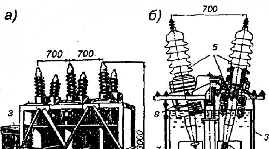
The MKP-35 switch (oil, chamber, substation, for a voltage of 35 kV is shown in Fig. 1. It consists of three oval-shaped tanks 1 (Fig. 1, a) mounted on a welded frame 2. The switch is controlled using a drive in cabinet 3. A winch 4 is used to lower and raise the tanks. 
Rice. 1:
a - switch type MKP-35; b - section of the switch pole In Fig. 1, b shows a section of one pole of the switch, which shows: tank 3 and arc-extinguishing chamber 1, having insulating screens 2. High-voltage inputs 5 are located on the lid of the tank. Movable contacts 7 are fixed on a cross-beam, which is connected by a rod b to the drive mechanism in the upper part of the tank .
An arc-extinguishing chamber is attached to the current-carrying rod of each input (Fig. 2) using two holder bolts 4. The chamber is closed with an insulating screen 1. The upper part of the chamber is metal (steel, brass), the lower part is assembled from insulating plates 9, which have special profile cutouts. When assembled, the plates are pulled together with textolite pins and form a Chamber, which has a central vertical channel with a neck 8. for the passage of the movable contact and two horizontal channels of the transverse blower with exit to the oil tank. 
a - arc-extinguishing chamber of the MKP-35 circuit breaker; b - the process of extinguishing the arc in the chamber
End type switch contacts. Their closure occurs in the upper part of the chambers, which has a metal body 6, in which there is a fixed contact 7. Spring 3 serves to soften shocks, prevent vibrations when turned on and create contact pressure in the on position. Flexible connection 2 provides good contact between the moving and fixed parts of the upper contact system (fixed contact). In the upper right part of the chamber there is a compartment 5 in which, when the tank is filled with oil, air remains, forming a buffer gas cushion. ,
When contacts 3 and 4 open (Fig. 2, b), an arc appears in the upper part of the chamber, which stretches following the movable contact 4, decomposes and evaporates the oil. The pressure in the main chamber increases sharply, since the exit from the chamber is blocked by the movable contact rod. The pressure is transferred to compartment 2, where the air of the gas cushion is compressed.
The moving contact, as it moves downwards, alternately opens the horizontal channels 6 of the transverse blast, into which oil and gases from the upper part of the chamber rush under high pressure. In this case, the arc stretches in a zigzag manner in the channels, intensively deionizes and goes out.
Extinguishing occurs in two arc extinguishing chambers simultaneously (Fig. 1, b), that is, two breaks in the electric arc are created for each phase, due to which the shutdown process is significantly accelerated (toff = 0.08 s). The MKP-35 switch is a high-speed switch. Intense deionization of the arc and its rapid extinction occur due to the following factors:
the presence of hydrogen in the gas bubble that appears during the decomposition of oil;
high pressure in a gas bubble;
stretching the arc in the longitudinal and transverse directions;
two current circuit breaks per phase;
passing alternating current through zero.
Rice. 3:
a - section of a pole of a switch type S-35; b - section of its arc-extinguishing chamber
The most important role in the operation of the switch is played by the buffer space, located in the upper part of the tank above the oil and filled with air. It allows the oil to expand upward, which reduces the pressure on the walls and bottom of the tank. If this space is not enough ( high level oil), the tank may explode.
When the oil level in the tank is low, hydrogen, which is part of the released gases and has a high temperature, rising upward, does not have time to cool, and combining with oxygen in the air in the buffer space can cause an explosion. Consequently, a switch explosion can occur both when the oil level rises and falls. During operation, the oil level is monitored; for this purpose, the tanks have oil indicators.
The S-35 35 kV circuit breaker was developed in the city of Sverdlovsk (Ekaterinburg). It is produced for a rated current of 630 A and is used in networks where a powerful MKP-35 switch is not required. Their main distinctive feature are arc extinguishing chambers and arc extinguishing processes in them.
The switch consists of three tanks, a section of one of them is shown in Fig. 3, a. Tank 14 has the shape of an elliptical cone, made of sheet steel, lined inside with insulation 11 made of electrical cardboard and equipped with an oil drain valve 13. The tank is secured using four tie rods 17 to a steel cover 1, on which two inputs are located. The main part of the input is a current-carrying rod 15, passed through a bakelite sleeve 5. Threaded tip 2 is used to connect external current-carrying parts. To increase moisture resistance, the space between the bakelite bushing 5 and the porcelain cover b is filled with frost-resistant mastic 4. The input is closed on top with a round cast cover 3. Current transformers 7 are installed on the inputs. L-shaped copper fixed contacts 9 are attached to the current-carrying rods 15 from below. The movable arc-extinguishing chamber 10 is mounted on an insulating rod 16, which moves inside the guide sleeve 8 under the action of the drive mechanism 18. Under the bottom of the tank there is heating device 12, which is turned on to heat the oil at ambient temperatures below -20°C.
A section of the arc chute is shown in Fig. 29, b. Housing 5 is assembled from two parts, made of lightweight synthetic material that can withstand high pressure, by connecting with coupling bolts 10. The internal cavity of the chamber is lined with arc-resistant insulating material 7. Bushings 4 and 6 made of arc-resistant material are installed in the exhaust holes located in the upper part and on the sides of the chamber. The chamber contains a movable contact bridge 8 with metal-ceramic soldering 12, supported by four contact springs 9.
Springs provide the necessary force in contact connections between fixed contacts 14, lined metal plates 13, and movable contact 8. The stroke of movable contact 8 is limited by two pairs of protrusions. 3 camera body air cushion is connected to the insulating rod 1 using a threaded connection and secured with a nut 2.
When switched off, the drive mechanism moves rod 1 together with the chamber downwards, two arcs are formed between the moving and fixed contacts, decomposing the oil into gases. The pressure in the chamber rises sharply and arcs are blown into the exhaust ports, this is facilitated by the air compressed in the air cushion chamber, which serves as a shock absorber that stores energy at the first moment of gas formation. As the chamber with the movable contact bridge moves downwards, the arcs stretch both transversely and longitudinally. In contact with cold layers of oil, the arcs are cooled, deionized and finally extinguished at the next transition of the current through zero.
It is necessary to maintain the oil level in the switch to avoid an explosion, as in the MKP-35. Switch S-35 is a high-speed switch.
The MKP-110M switch for a voltage of 110 kV is equipped with transverse oil blast arc-extinguishing chambers with multiple arc breaks. In Fig. 4, and a schematic section of the arc chambers during the process of disconnecting the circuit breaker is presented. The process follows a two-stage cycle: first, the contacts inside the chamber open and the current circuit in it opens; the current flowing through shunt resistors 7 with a resistance of 750-1000 Ohms decreases sharply; then the circuit opens outside the arcing chambers and two low-power arcs are easily extinguished in the oil environment of the circuit breaker tank.
Inside the chamber, enclosed in a thick-walled bakelite cylinder 1, an insulating rod 4 with movable contact bridges 3, elastically secured with springs, runs along the axis. On the inner side surface of the cylinder there are fixed contacts 2, arranged in pairs opposite each other. With the help of external movable contacts located on the traverse 5, when the rod 4 is turned on, the contact bridges 3 move upward, overcoming the resistance of the springs, and close the circuit.
Rice. 4:
A -g- principle arc extinguishing in a circuit breaker type MKP-110M; b - section of its phase
When the switch is turned off, two arcs are formed on each contact bridge: first, an extinguishable one, against the exhaust hole in the cylinder wall, partially covered with fiber linings; then the gas-generating (after about a quarter of the period) generating arcs decompose the oil in the chamber, generate gases that maintain high pressure in the chamber and a transverse gas-oil blast through exhaust hole 6. Thus, eight current circuit breaks are created in two chambers per phase, which contributes to extinguishing emerging arcs.
Shunt resistors 7, enclosed in separate bakelite cylinders with holes for oil circulation and cooling of nichrome spirals wound on bakelite cylinders inside cylinders with holes. These resistors ensure uniform distribution of voltage between the two arcing chambers, reducing the speed of voltage recovery and reducing the voltage appearing on the contacts of the switch after shutdown, reducing the power of the arcs when the circuit is finally broken. On the other hand, the use of shunt resistors increases the cost of the switch design and also slightly increases the time complete shutdown circuit, since after the arcs in the chambers go out, a small accompanying current flows through the shunt resistors, which is switched off by the contacts of the traverse 5. The duration of the arc with the accompanying current is from 0.06 to 0.08 s.
A section of one phase of the MKP-110M switch is shown in Fig. 4, b. The circuit breaker has three cylindrical tanks 1 installed on the foundation. Oil-filled bushings 3 are installed on the tank covers, to the rods of which arc extinguishing chambers 4 are attached. Shunt resistors in bakelite cylinders are connected parallel to the arc extinguishing chambers. The traverse 7 with movable contacts is fixed on a rod 5, which moves when turned on and off in the guide device 6 under the action of the on and off mechanism 2, with which the locking contacts 9 are connected. Inner surface The tank is insulated with two layers of electrical plywood 10. Oil drain valve 12 is used to drain used oil and supply fresh oil through the oil pipeline. Oil heating device 14 is used in winter time at an ambient temperature below -20°C. At the bottom of the tank there is a hole 13, used for penetration into the tank by repair personnel for internal inspection and repair of the circuit breaker. Built-in current transformers 8 are installed on inputs 3, the current-carrying rods of which are the primary windings for the current transformers.
The U-110 110 kV circuit breaker was developed by the Uralelectrotyazhmash plant. The appearance, overall dimensions, operating principle are in many ways similar to the MKP-110M switch, however, the use of new materials and some constructive developments made it possible to increase the operating currents and switched powers of the circuit breaker, to reduce specific consumption materials per unit of switched power.
In Fig. 5, a section of the switch phase is shown. In each of the two arc-extinguishing chambers 3 there are two pairs of series-connected contacts, between which two arcs arise when disconnected. The first pair of contacts is formed by the upper fixed contact 15 and the movable 17 (Fig. 5, b), the second by the intermediate contact 24 and the movable 22. Between contacts 24 and 17 there is an electrical connection in the form of a sliding contact. Mechanically, both movable contacts 17 and 22 are connected to the external contact 21 of the arc chute, and contact 17 is isolated from contacts 21 and 22 by bushing 18.
When the switch is turned off, the contacts inside the chamber are open: contact 21 and the mechanically connected contacts 17 and 22 are retracted downward by the preload spring 20. The crossbar 2 is lowered down, so that another, external, gap is formed between its movable contact 27 and the external movable contact of the chamber 21 .

Rice. 5:
a - section of the phase of the U-110 type switch; b - section of its arc-extinguishing chamber
When the traverse switch 2 is turned on, under the action of the drive mechanism 9, which moves the movable rod
system in the guide device 5, rises upward, its contact 27 first comes into contact with contact 21 and forms a current circuit through resistors 4, shunting the arc-extinguishing chambers, then moves contact 21 and contacts 22 and 17, synchronously closing the current circuit through contact pairs 15- 17 and 22-24.
When the switch is turned off, traverse 2 falls down under the action of the switch's opening spring. At the first stage, contact 21 is lowered along with it, pressed against contact 27 by a pressed spring 20, both pairs of contacts 15-17 and 22-24 open. In the resulting breaks in the current circuit, two arcs are formed in each chamber. Oil in chambers under influence high temperature the arc is actively decomposing and the pressure is growing rapidly. The blowing slot 25 of the damping grid 23 opens when contact 22 is lowered, creating a transverse gas-oil arc blast. The arc goes out at the first transition of the current through zero. The second slot 26 is used to extinguish the arc when switching off small short-circuit currents or operating currents. A similar process occurs in the grid 16. The gases formed during the arc extinguishing process are ejected into the tank 1 through the nozzle 11. The screen 19 limits the downward movement of the movable contact 21. After the contact stops moving, the movable crossbeam 2 continues to move downwards and two arcs are formed outside the arc extinguishing chambers between the contacts 21 and 27. The current in these arcs is small, since shunt resistors 4 are included in the circuit, so the arcs are extinguished quite quickly.
The arcing chamber has a cylindrical body 14 made of thick-walled bakelite. It is attached by a holder 12 to the current-carrying rod of the oil-filled bushing 14, the oil level in which is controlled by an oil indicator 8. Current transformers 7 are installed on the bushings on removable stands, allowing them to be replaced without the volume of bushings. Intra-tank insulation 6 prevents the arc from transferring to the grounded tank 1 at the moment the switch is turned off. To heat the oil in winter, a heating device 12 is provided on each switch tank.
The main advantages of multi-volume oil switches: simplicity of design; high breaking capacity; possibility of using built-in current transformers; outdoor installation, allowing you to do without special rooms.
Main disadvantages of switches: large mass transformer oil(230 kg - S-35; 800 kg - MKP-35; 8500 kg -
MKP-110; 27,000 kg - U-220), hence the need to have a large supply for replacement; explosion and fire hazard (in fairness, it should be noted that in the latest developments of switches this drawback was practically eliminated); The large weight and dimensions make it difficult to transport and install the switches.
MINISTRY OF ENERGY AND ELECTRIFICATION OF THE USSR
GLAVENERGOREMONT
MANAGEMENT
FOR OVERHAUL REPAIRS
OIL SWITCH
MKP-35-1000-25
RD 34.47.604
SERVICE OF EXCELLENCE FOR SOYUZTEKHENERGO
Moscow 1986
AGREED: I CONFIRM:
Deputy Director
for scientific work
Research Institute of Software Chief Engineer
"Uralelektrotyazhmash" Glavenergoremont
A.I. Utkin V.I. KURKOVICH
1. Introduction
1.1. The manual for the overhaul of the oil switch MKP-35-1000-25* is a technical document, compliance with the requirements of which is mandatory for personnel performing overhaul of the switch.
*Hereinafter referred to as the Guide for brevity.
1.2. The manual provides for the use of the most rational forms of organizing repair work and advanced technological methods for their implementation.
1.3. The Guide contains:
A) technical requirements to volume and quality repair work and to the methods of their implementation (regardless of the organizational and technical level of repair units);
b) method of control during the repair of parts and assembly units;
c) rules for accepting equipment for repair and repair;
d) criteria for assessing the quality of repair work.
1.4. The manual was developed based on the technical documentation of the manufacturer.
2. Organization of work to repair the circuit breaker
2.1. General provisions
2.1.1. The composition of the team (link) for repairing the circuit breaker is established depending on the intended scope of work (the duration of repair work is determined by the network repair schedule).
2.1.2. The timing of repair work should be determined taking into account the following:
a) the composition of the brigade must correspond technological scheme repair. Changing the composition of the team until the repair is completed is not allowed;
c) to ensure the completion of repair work within the established time frame, it is recommended to issue standardized task plans and use the aggregate-unit method of repair using the exchange stock of parts;
d) the work schedule of repair personnel should be subject to the maximum reduction in the duration of repair work.
2.1.3. The manual provides for a repair team of 4 people: electricians of the 5th category - 1 person, 3rd category - 2 people, 2nd category - 1 person.
2.1.4. Labor costs for overhaul of the circuit breaker are determined on the basis of the “Time Standards for Overhaul, current repairs and operational maintenance of equipment for substations 35 - 500 kV and distribution networks 0.4 - 20 kV", approved by the USSR Ministry of Energy in 1971.
Standards for overhaul of oil switch MKP-35-1000-25 (without changing inputs) - 41.8 man-hours, with changing inputs - 52 man-hours.
2.2. Preparation for repair
2.2.1. Preparation for major repairs is carried out in accordance with the specific scope of work provided for of this type equipment.
2.2.2. Before the start of repairs, a team of workers with appropriate qualifications who have undergone training, knowledge testing and instructions on the rules is staffed safe management works
2.2.3. Before starting work, the team is given a planned task with a specific list of work and an indication of its volume, labor costs and completion date, as well as technological instructions and requirements.
2.2.4. Before starting repairs you must:
a) prepare a set of plumbing tools, as well as instruments and measuring tools (applications,);
b) prepare basic and auxiliary materials, spare parts for repairs (applications,); The list and quantity of materials should be specified in accordance with the scope of work;
c) prepare and check protective equipment;
d) coordinate the work procedure with other teams performing related work.
2.2.5. The performers, together with the repair manager, after drawing up a general work order for the repair of the circuit breaker, must:
a) make sure that all measures to ensure the safety of work are carried out correctly and completely;
b) carry out all fire safety measures.
2.3. Quality control of repair work
2.3.1. Quality control of repair work by the contractor is carried out in the following order:
a) check, together with the repair manager, the condition of each assembly unit during the repair. In this case, the manager must give instructions on the methods of repair and supplement, (clarify) the technical requirements for repair, according to which the assembly unit will be accepted from repair and the quality of repair work will be assessed;
b) present completed hidden work and completed intermediate operations to the manager for acceptance and quality assessment;
c) after completing all repair work, present the circuit breaker for final acceptance.
2.3.2. The final acceptance of the product as a whole is carried out by representatives of the operational department together with the repair manager, for which a technical repair report is drawn up, which is signed by representatives of both parties.
3. Acceptance of the circuit breaker for repair
3.1. Before the start of a major overhaul, a commission of representatives of the operational and repair departments, with the obligatory participation of the repair manager, checks the state of readiness for repair:
a) availability of a statement of scope of work overhaul;
b) availability of materials, spare parts, special equipment and tools;
c) the state of safety measures, labor protection and fire safety;
d) availability of a capital repair schedule.
3.2. When accepting the circuit breaker for repair, it is necessary to familiarize yourself with the list of defects and the scope of work performed during the previous major overhaul and during the period between repairs.
Technical data of the oil switch MKP-35-1000-25
(meet the requirements of GOST 687 -70)
Voltage, kB:
nominal 35
highest working 40.5
Rated current, A 1000
Limit through current, kA:
effective value of periodic component 25
amplitude 63
Limit thermal stability current, kA 25
Rated shutdown current, kA 25
Shutdown power, MV-A 1750
Thermal stability current flow time, s 4
Permissible number of short circuit trips without circuit breaker inspection 5
Weight, kg:
switch with drive (without oil) 2750/2830
drive 310
transformer oil 800
Technical data of the electromagnetic drive PE-31
(meets the requirements of GOST 688-67)
Nominal voltage of the electromagnet, V:
including 110/220
disconnecting 110/220
Limits of operational operation of the drive in terms of voltage at the terminals of its windings, % of the nominal:
closing electromagnet 85 - 110
disconnecting electromagnet 65 - 120
Current consumption of the electromagnet winding at an ambient temperature of 20 °C, A:
including 248/124
disconnecting 10/5
Current consumption of the contactor switching winding at a voltage of 110/220 V, A 2/1
Resistance of electromagnet windings, Ohm:
including (one section) 0.85 - 0.92
disconnecting (one section) 20.25 - 23.75
4. Disassembling the switch
4.1. General instructions for defecating the circuit breaker
4.1.1. Inspect the switch, make sure there are no oil leaks. If there is a leak, determine the cause.
4.1.2. Check that the switch frame is installed correctly and its upper base is horizontal.
4.1.3. Inspect the fastening of the frame to the foundation (anchor bolts must have locknuts). The frame must be reliably grounded with a steel strip with a cross-section of at least 25
´ 4 mm.4.1.4. Check the condition of the winch and cable.
4.1.5. Make sure the safety valve rupture screw is intact.
4.1.6. Carry out several test switches on and off; determine the preliminary scope of repairs.
4.2.1. Disconnect the tires.
4.2.2. Unscrew the locking screws 2 (Fig.), unscrew the nuts 1 and the cap with tip 3.
4.2.3. Unscrew the locking screw II from nut 10, remove gasket (brass washer) 4, centering washer 5 and gasket 6.
4.2.6. Install casing 7, screw on the nuts.
4.2.7. Install rubber gasket 6, centering washer 5, gasket (brass washer) 4, screw in nut 10, screw in locking screw 11.
4.2.8. Screw on the cap with tip 3, nuts 1 and screw in locking screws 2.
4.3. General operational disassembly of the circuit breaker
4.3.1. Drain the oil from the switch tanks into a previously prepared container. Check the operation of the oil indicators.
4.3.2. Turn off the oil heating device in the tanks.
4.3.3. Place the cable on the rollers 3 of the tank (Fig.), and pull it lightly. Unscrew the nuts from the bolts securing the tank, remove the washers, lower tank 1 until the cable is completely loosened, remove the cable from the tank rollers. The tanks of the other two phases are lowered similarly.
4.3.4. Unscrew the bolts securing the screen 1 (Fig.), lower the screen until it stops against the traverse.
4.3.5. Unscrew the bolts securing the housing 2 to the holder 3, lower the housing with the camera.
4.3.6. Lift the screen and place it on the bottom of the bakelite bushing. Take out the body and camera, then remove the screen.
4.3.7. Disconnect the outer and inner ends connected to current transformer 2 (see figure). Check for markings first. If not available, apply.
4.3.8. Unscrew the nuts and remove the current transformers.
Note. Only remove current transformers when they need to be replaced or dried.
4.3.9. Unscrew the nuts from the input bolts, remove the input and gasket (dismantle the input only if necessary).
5. Preparation for defect detection and repair
5.1. Thoroughly clean the components and parts from dirt, old lubricant residues and corrosion-mechanical wear products, rinse in B-70 gasoline and dry for inspection and identification of defects.
5.2. Remove traces of corrosion, varnish, and paint with sandpaper, cleaning these areas to a metallic shine.
6. Technical requirements for defect detection and repair of circuit breaker parts and assemblies
6.1. Bolts, studs, nuts, threaded connections are subject to rejection if:
a) cracks;
b) dents, nicks, chipping of more than two turns;
c) the bent of the bolt (stud) is more than 1 mm per 100 mm of length.
6.1.1. Edges and corners on bolt heads and nuts should not be crushed or cut off. If the edges are worn more than 0.5 mm (from the nominal size), the bolt or nut is rejected.
6.1.2. Holes for cotter pins in bolts and studs should not be clogged and should be noticeably enlarged.
6.1.3. When disassembling, serviceable studs should not be removed from parts. A tight and tight fit of the studs is checked by tapping. If a rattling sound is heard, then the pin should be unscrewed and the fit restored.
6.2. Shafts, axles.
6.2.1. Axles must be replaced if:
a) wear in diameter, ovality in places of wear;
b) axial curvature of more than 0.2 - 0.3 mm;
c) cracks, scuffs on the friction surfaces of shafts and axles;
d) saddles on the working friction surfaces of shafts and axles.
6.2.2. Shafts and axles should be straightened in a cold state with light blows of a hammer on a stable support. To prevent damage to parts, place wooden or lead spacers on the support and under the hammer. Check the curvature using a plumb line.
6.2.3. It is allowed to reduce the shaft, axle and ellipse of the part at the wear site by no more than 0.4 mm; check the diameter and ellipse of the shafts and axes with a micrometer.
6.2.4. It is allowed to increase the diameter of the holes and their ellipse by no more than 0.4 mm. Check the diameter and ellipse of the hole with a caliper.
6.2.5. Remove burrs on the surfaces of the axles carefully with a fine file or sandpaper.
6.2.6. Saddles and dents on the working surfaces of the axles are determined by measuring the smallest diameter in deformed areas. Filing of saddles and dents on working surfaces is not allowed.
6.3. Lock washers and spring washers must be discarded:
a) in the presence of cracks and fractures;
b) with loss of elasticity;
c) if the spread of the spring washers is less than one and a half of its thickness.
6.3.1. The normal spread of the washer is equal to twice its thickness, the acceptable one is one and a half.
6.3.2. If the fit is loosened or the alignment pins are worn, expand the hole under them and install repair size pins.
6.4. Cylindrical coil springs are subject to rejection if:
a) cracks and breaks;
b) uneven pitch of coils along the entire length of the spring of more than 10%;
c) deviations of the spring axis from the perpendicular to the end plane of more than 5 mm per 100 mm of length;
d) loss of spring elasticity is allowed within 5 - 10% of the normal value.
6.5. Seals.
6.5.1. Self-clamping oil seals are subject to rejection if:
a) dents, deep scratches and others mechanical damage housings and covers;
b) cracks, cuts, tears, deep scratches on the surface of the cuff in contact with the shaft;
c) loose fit of the oil seal seal in the housing;
d) breakage or damage to the spring.
6.5.2. All felt seals and seals must be replaced during major repairs.
6.6. Sealing gaskets.
6.6.1. Cardboard gaskets should not have any torn spots or tears.
6.6.2. The uneven thickness of the gasket should not exceed 0.1 mm along the entire length.
6.6.3. The surface of the gasket must be smooth, clean, without folds or wrinkles.
6.6.4. Rubber gaskets should not have cracks, shear, or residual deformation. If the listed defects are present or there is loss of elasticity, replace the gasket.
6.7. Current transformers
6.7.1. Measure the insulation resistance of the secondary winding with a megohmmeter for a voltage of 1000 V. The insulation resistance of the secondary winding with connected secondary circuits must be at least 1 MOhm.
6.7.2. Check the condition of insulation surfaces. Wrap the damaged areas with keeper tape, varnish with bakelite varnish, and dry.
6.8.1. Movable contact
Quantity per product - 3.
|
Position in the picture |
Possible defect |
Method for eliminating the defect |
|
|
Burning, melting. Melting more than permissible (to a depth of more than 2 mm) |
File, clean Replace |
||
|
Thread damage |
Restore with thread cutting tool |
||
|
Inspection. Magnifying glass LP-1-7* |
Replace |
1. Cracks and deformation are not allowed.
3. After filing, indentations of no more than 0.5 mm are allowed.
6.8.2. Capacitor input (Fig.)
Quantity per product - 6.

|
Position in the picture |
Possible defect |
Method for identifying a defect and control tool |
Method for eliminating the defect |
|
Cracks, chips with total area whiter than 10 cm 2 |
Inspection. Measurement. Ruler |
Replace |
|
|
The same area up to 10 cm 2 |
Inspection. Measurement. Ruler |
Clean, degrease, coat with a layer of bakelite varnish |
|
|
Oxidation, carbon deposits |
Clear |
||
|
Partial chipping of the putty of the reinforcement joints |
Finish with subsequent varnish coating |
||
|
Cracks, peeling of mastic from the walls |
Replace |
Technical requirements for the repaired part
1. The insulation resistance must be at least 1000 megohms.
2. Dielectric loss tangenttg dshould be no more than 3% (at a temperature of 20± 5 °C).
3. The bushing must withstand the high voltage test of 95 kV for 5 minutes.
4. Ohmic input resistance is no more than 60 μOhm.
6.8.3. Arc chamber (Fig.)
Quantity per product - 6.

|
Position in the picture |
Possible defect |
Method for identifying a defect and control tool |
Method for eliminating the defect |
|
Burning, melting and shells |
File down, maintaining the original shape. Sinkholes on the contact surface with a depth of no more than 0.5 mm are allowed. Restore silver coating using electric spark method |
||
|
Warping and burning of insulating plates |
Replace |
||
|
Burnout of more than 2/3 of the compound layer |
Replace |
||
|
More than 1/4 of the thickness of the flexible connection package is broken |
Replace |
Technical requirements for the repaired part
1. Cracks and deformations are not allowed.
2. Breaking the thread on more than one turn is not allowed.
3. Torn sheets If there is a break less than 1/4 of the thickness, cut off.
Quantity per product - 3.

|
Position in the picture |
Possible defect |
Method for identifying a defect and control tool |
Method for eliminating the defect |
|
Oil indicator leaking |
Replace the defective part, clean the oil indicator glass |
||
|
Significant warping of in-tank insulation |
Inspecting a tank that is not filled with oil |
Replace |
|
|
Eliminate by editing |
|||
|
Cracks in welds |
Inspecting the oil-filled tank |
Eliminate with tea leaves |
|
|
Damage to anti-corrosion coating |
Clean damaged areas, degrease, restore coating |
||
|
Oil drain valve leaking |
Coat with putty and paint with oil paint |
Technical requirements for the repaired part
Cracks and deformations are not allowed.
7. Assembling the circuit breaker components
7.1. Installation of entries
7.1.1. Place the gasket on the cover hole under the input flange, lift the input onto the switch, carefully install it into the cover hole, center until the axes of the mounting holes coincide. Finally adjust the input position. Secure the inlet to the cover with bolts and nuts and washers. To avoid transfer, tighten the nuts alternately diagonally.
7.2. Assembly of arc extinguishing device and contact system
7.2.1. Attach flexible connections 4 to holder 3 (see Fig.) and fixed contact 6. Make sure that the ends of the bolts securing the flexible connections do not go inside the annular recess of the cup in which spring 5 is located.
7.2.2. Install spring 5, screw in the guide bolt. Make sure that the cuts of the bolt head are located opposite the holes in the wall of the brass glass.
7.2.3. Install housing 2, secure with bolts to holder 3.
7.2.4. Assemble a set of insulating plates 7, secure them to the body with 2 insulated bolts.
7.2.5. Lift the screen and place it on the bottom of the bakelite bushing.
7.2.6. Install the camera onto the current-carrying input rod and secure it using pads and bolts.
7.2.7. Check the camera installation dimensions:
Deviation from the vertical ± 1 mm at the full height of the camera;
The distance from the camera to the axis of the guide pipe is within 90 ± 1 mm.
In this case, the moving contacts must move in the chamber without touching its walls.
Adjustment is made by changing the position of the camera on the current-carrying rod.
7.2.8. Fix the position of the camera on the current-carrying input rod with a locking screw.
7.2.9. Place screen 1 on the camera and secure it with bolts.
8. Switch adjustment
8.1. Check the operation of the drive mechanism. Turn on the switch slowly using a DV-33 jack. At the same time, check whether there are any areas where the moving system is stuck and an increase in the muscular effort required to turn on is felt. During the switching process (during the entire stroke), loosen the force on the jack handle several times, creating the possibility of reverse motion of the moving system.
Check to see if any intermediate position stop (freezing) of the movable circuit breaker system.
8.2. Check the correct position of the drive mechanism levers using a template (Fig. ).
When the levers are in the correct position, the axles of the drive mechanism should touch the template. An undershoot of the middle axis relative to the template line by 2 - 3 mm is allowed.
Attention! The transition of the middle axis beyond the template line towards the thrust pin is not allowed.
8.3. Inconsistency with the axle position pattern can be adjusted by shortening or lengthening the rods between the drive mechanisms different phases screwing in their ends.
If there is an equal discrepancy between the pattern of all three phases, adjustment should be made by changing the length of the vertical rod going to the drive.
8.4. Check the gap (1.5 - 2 mm) between the drive mechanism lever and the thrust pin.
Adjust the position of the stop pin in the on position of the switch.
8.5. Check the full stroke of the moving contact.
With the switch in the “on” position, make a mark on the rod at the lower end of the guide pipe. Turn off the switch and mark the rod again.
The full stroke of the rod is 270 - 280 mm.
8.6. Check the simultaneous closure of the pole contacts (discrepancy of no more than 2 mm is allowed), the closure of contacts between poles (divergence of no more than 4 mm).
Adjust:
a) lowering or raising cameras with fixed contacts;
b) screwing or unscrewing the movable contacts (rods) in the traverse liners.
8.7. Measure the contact resistance of each pole (no more than 300 μOhm). Measure with the secondary winding of the current transformers closed to the operating load or short-circuited.
8.8. Take a vibration record, check the speed of movement of the moving contacts of the switch (without oil) when turning off and on:
at the moment of contact opening - 1.7 - 2.3 m/s and 1.8 - 2.6 m/s; maximum - 3.0 - 3.6 m/s and 2.1 - 5.9 m/s, respectively.
Checking simultaneity, stroke in contacts (pressing - 16± 1 mm), it is recommended to take speed and time characteristics using a remote control (Fig. ).
9. Drive repair
9.1. Drive Inspection
9.1.1. Clean and inspect all accessible parts of the drive from dust, dirt and old grease, check:
a) the condition of the axles and springs;
b) drive mount;
c) degree of corrosion of parts;
d) absence of dents and hardening on working surfaces.
Carry out defect detection and repair of drive parts in accordance with Section. .
9.1.2. Check for distortion and jamming of the electromagnet cores.
9.1.3. Pay attention to the reliability of the connections and their fastening.
9.1.4. Pay special attention to the presence in all links of the transmission mechanisms of devices that prevent spontaneous unscrewing (lock nuts, spring washers, etc.).
9.1.5. Inspect the block contacts KBO and KKB. Pay attention to the condition of the moving and fixed contacts, springs, clamps, contact screws, rods and levers.
9.1.6. Specify the final scope of drive repair. Disassemble the drive only if faults are detected that prevent further normal operation drive.
9.2. Drive regulation
Attention! To avoid injury in the event of accidental shutdown during the drive adjustment process, it is necessary to screw the safety bolt 6 (Fig. ) all the way to the shutdown pawl 5. When shutting down or completing the adjustment, unscrew bolt 6, setting the gap to 13 - 15 mm.
9.2.1. Maintain gaps and recesses of pawls in accordance with Fig. . Adjust the drop value of 5 - 8 mm of the disconnecting pawl 5 with bolt 2 and screw 4.
9.2.2. Check the reliability of the engagement of lever 3 with the latch when the release pawl 5 rests on bolt 6. Adjust with bolt 1.
9.2.3. Check that the position of the KBB and KBO contacts corresponds to the position of the switch. The on position of the switch must correspond to the off position of the KBB contact and the on position of the KBO contact.
9.2.4. Check the opening of the KBV block contacts at the end of the drive switching stroke. The test is carried out at a minimum voltage (93.5/187 V) at the terminals of the switching electromagnet at the moment of switching on.
9.2.5. Adjust the gap between the pawls and ratchets at the block contacts in accordance with Fig. . The adjustment is made by moving the fork 4 (Fig. ) along the rod 3 and moving the threaded pin 2. The fork 4 should rotate on the rod 3.
Attention! To avoid damage to the transmission links of the block contacts, be careful when adjusting and attach the rod to the levers only after first checking its length in both extreme positions of the drive.
9.2.6. Coat the core of the switching electromagnet with a special lubricant (one part CIATIM-203 and one part amorphous or silver graphite).
10. Final assembly and testing of the circuit breaker
10.1. Clean the tank from dirt, wipe it, check the serviceability of the internal insulation.
10.2. Check the serviceability of the oil drain valves and electric heating. Turn on the tubular heaters at a voltage equal to 50% of the nominal voltage for 2 hours - for drying.
10.3. Install a removable winch, put the winch cable on the tank rollers 3 (see fig.) and use the winch to lift the tanks and secure them.
10.4. Measure the shaft rotation angle, which should be 57°.
10.5. Fill the tanks with oil, the breakdown voltage of which is not lower than 35 kV. When filling, check the operation of the oil indicators and check for leaks. After filling and settling the oil, take a sample. The breakdown voltage of the oil must be at least 30 kV.
10.6. Paint the switch.
10.7. Connect tire deflations.
10.8. Determine the lowest voltage of the closing electromagnet at which the drive is able to turn on the switch without load.
10.9. Determine the lowest voltage of the tripping electromagnet at which the drive is able to trip the circuit breaker.
10.10. Check the joint operation of the switch with the drive by turning the switch on and off five times.
10.11. Before commissioning, test the switch with a voltage of 95 kV for 1 minute.
Annex 1
List of tools required for overhaul of the circuit breaker
|
Name |
Designation |
Standard designation |
Quantity, pcs. |
|
|
1. Open-end wrenches, double-sided: |
||||
|
S = 8´ 10 mm |
Key 7811-0003 |
|||
|
S = 12´ 14 mm |
Key 7811-0021 |
|||
|
S = 14´ 17 mm |
Key 7811-0022 |
|||
|
S = 17´ 19 mm |
Key 7811-0023 |
|||
|
S = 22´ 24 mm |
Key 7811-0025 |
|||
|
2. Open-end wrenches, single-sided: |
||||
|
Key 7811-0142 |
||||
|
Key 7811-0146 |
||||
|
3. Pipe lever wrench No. 1 |
||||
|
4. Combination pliers, 200 mm long |
Pliers, 200 |
|||
|
5. Flat, blunt-nosed file |
File 2820-0029 |
|||
|
File 2820-0029 |
||||
|
6. Screwdriver for mechanics |
Screwdriver 7810-0309 |
|||
|
7. Bench hammer, steel, weighing 400 g |
Hammer 7850-0034 |
|||
|
8. Metric measuring ruler |
Line 1-500 |
|||
|
Line 1-150 |
||||
|
9. Vernier caliper |
||||
|
10. Bar level |
Level 150 mm long |
|||
|
13. Manual jack |
||||
|
14. Device for taking vibrograms |
||||
|
15. Template |
||||
|
16. Electric drill |
||||
|
17. Drills with a diameter of 6; 8 mm |
||||
|
18. Taps |
||||
Appendix 2
List of devices used during repairs
|
Name and designation |
Purpose and a brief description of |
|
1. Portable bridge - MD-16 |
Device for measuring capacitance and dielectric loss angle tgd |
|
2. Megaohmmeter M-1101 |
1000 V insulation resistance measurement |
|
3. Microohmmeter M-246 |
Measuring contact resistance |
|
4. Vibrograph |
Vibrogram removal, 12 V |
|
5. Voltmeter E-L5 |
0-600 V, class 0.5 |
|
6. Switch adjustment panel. Development of the Yuzhenergoremont enterprise |
Checking the simultaneous closure of contacts of a pole and between poles, taking characteristics, power supply of a vibrograph, lighting |
|
7. Installation for silvering by electrospark method EFI-54 |
Restoration of silver-plated contact surfaces (in the workshop only). The thickness of the applied layer is 0.01 mm. Maximum productivity up to 10 cm 2 /min |
|
8. Folding pocket magnifying glass LP-1-7* |
|
|
9. RSPS dual resistor |
340 ohms ± 10% 1 A - in series 2 A - parallel |
Appendix 3
Standards for material consumption for major repairs of a circuit breaker
|
Name |
Standard designation |
Consumption rate for repairing one circuit breaker |
|||||||||||||||||||||||||||||||||||||||||||||||||||||||||||||||||||||||||||||||||||||||||||||||||||||||||||||||||||||||||||||||||||
|
Transformer oil TKp, kg |
|||||||||||||||||||||||||||||||||||||||||||||||||||||||||||||||||||||||||||||||||||||||||||||||||||||||||||||||||||||||||||||||||||||
|
Grease CIATIM-203, kg |
|||||||||||||||||||||||||||||||||||||||||||||||||||||||||||||||||||||||||||||||||||||||||||||||||||||||||||||||||||||||||||||||||||||
|
Aviation gasoline B-70, l |
|||||||||||||||||||||||||||||||||||||||||||||||||||||||||||||||||||||||||||||||||||||||||||||||||||||||||||||||||||||||||||||||||||||
|
Wiping rags, kg |
|||||||||||||||||||||||||||||||||||||||||||||||||||||||||||||||||||||||||||||||||||||||||||||||||||||||||||||||||||||||||||||||||||||
|
Sanding paper, different, m 2 |
|||||||||||||||||||||||||||||||||||||||||||||||||||||||||||||||||||||||||||||||||||||||||||||||||||||||||||||||||||||||||||||||||||||
|
Paint yellow, red, green, gray, kg |
Of necessity |
||||||||||||||||||||||||||||||||||||||||||||||||||||||||||||||||||||||||||||||||||||||||||||||||||||||||||||||||||||||||||||||||||||
|
Electrical insulating cardboard EM, 1 mm thick, kg |
|||||||||||||||||||||||||||||||||||||||||||||||||||||||||||||||||||||||||||||||||||||||||||||||||||||||||||||||||||||||||||||||||||||
|
Technical sheet rubber, kg: |
|||||||||||||||||||||||||||||||||||||||||||||||||||||||||||||||||||||||||||||||||||||||||||||||||||||||||||||||||||||||||||||||||||||
|
-»- Spare parts kit available upon special order
Appendix 5List of main indicators of the technical condition of the circuit breaker after major repairsPower system (REU) _________________________________________________ Company _________________________________________________ Statement Type ______________________ Manufacturer __________________________ Serial number _______________________ Year of manufacture ________________ Reason for repair________(scheduled, extraordinary, after shutdown_________ maximum number of short circuits)______________________________ Start of repairs ____________________________ (date of) Completion of repairs _________________________ (date of) 1. List of overhaul of circuit breaker assembly units (to be completed for assembly units that required replacement or overhaul of parts) 2. Switch adjustment
3. Testing a switch with an electromagnetic drive
4. Conclusion
| |||||||||||||||||||||||||||||||||||||||||||||||||||||||||||||||||||||||||||||||||||||||||||||||||||||||||||||||||||||||||||||||||||||
COMPLETED by the Chisinau department of the Central Design Bureau of Glavenergoremont
Authors: engineers S.A. Fridman, V.I. Smolyak, R.D. Mirsoyapov, I.M. Chernyakhovsky, Yu.Ya. Agapov, Yu.I. Popelnitsky
Editor Eng. L.F.Tafipolsky
AGREED BY THE CHIEF ENGINEER production association"Uralelektrotyazhmash" by A. Kazantsev March 29, 1974
APPROVED by the Chief Engineer of Glavenergoremont V. Kurkovich on September 26, 1974
INTRODUCTION
INTRODUCTION
The manual for organizing the technology of overhaul of the oil circuit breaker VMD-35/600 provides for the use by repair personnel of power enterprises and other specialized enterprises of the most rational forms of organizing repair work and advanced technological methods for their implementation.
The manual has been developed based on the manufacturer's drawings and instructions and best repair experience at a number of enterprises.
The Manual defines the strict sequence and scope of repair operations, provides regulatory materials on technology and labor costs for repairs, the qualifications of repair personnel, as well as recommendations for identifying defects in parts. A list of tools (tools, fixtures, fasteners, etc.) necessary to carry out repair work is given (Appendices 1, 2, 3 and 4).
The total cost of a major overhaul of one switch is 28.2 man-hours, including 24.0 man-hours for direct repairs and 4.2 man-hours for setting up the switch.
Labor costs indicated in operational cards cannot be used to determine the timing and cost of repair work, since they do not take into account the time for preparatory and final work, downtime, breaks, rest, etc. This time represents approximately 8.5% of the total time required to repair a circuit breaker.
I. GENERAL PROVISIONS
This Guide is intended for manufacturing enterprises as a regulatory document when planning, preparing and carrying out repair work.
Since the Manual provides for the repair of all components of the circuit breaker, the total labor costs are higher than the standard ones. The scope of repair work can be reduced or increased by the decision of those responsible for the operation and repair of equipment, but the actual labor costs should not exceed the standard ones.
Further improvement of this Manual, aimed at improving the quality, level of organization and performance of repair work, and reducing repair time, will be carried out as new technological solutions are accumulated and adopted.
The overhaul technology involves replacing damaged or worn parts with spare parts.
Repairing parts that prolongs equipment downtime for repairs is not recommended. Repair of such parts is carried out during the period between repairs, using them in the future as an exchange stock of spare parts.
The manual provides for inspection and repair of relay protection devices, automation, secondary switching circuits and electrical tests by personnel of the relevant services.
The labor costs given in the Manual are determined on the basis of the “Time standards for capital, current repairs and operational maintenance of equipment at 35-500 kV substations” approved by the USSR Ministry of Energy in 1971, and in the future can be reduced by improving the organization and technology of repairs performed. works
During the work process, repair personnel are obliged to strictly follow the current safety regulations.
Ensuring conditions for the safe performance of repair work is the responsibility of the operational (operational) personnel of the power grid enterprise and power plant.
II. PREPARATION FOR A MAJOR REPAIR
Preparations for major overhauls must be carried out in accordance with the specific scope of work provided for this equipment.
The most rational is the following procedure for performing preparatory work:
- familiarization with the list of scope of repair work;
- familiarization with the measures recommended by factory instructions, circulars of the Main Technical Directorate of the USSR Ministry of Energy to improve the reliability of equipment operation;
- familiarization with the documentation of previous repairs or installations;
- determination of the qualification and quantitative composition of the repair team;
- working out with the repair personnel instructions on the organization and technology of major repairs of the circuit breaker;
- development of a plan for equipping workplaces and placing parts, assemblies, fixtures and tools.
Before starting repair work, you should check:
- availability of necessary spare parts;
- availability of technical documentation;
- availability of devices, tools, equipment and means of mechanization of work;
- availability of lifting and transport mechanisms and rigging devices and their suitability for operation in accordance with the rules of the USSR State Mining and Technical Supervision (together with operating personnel);
- suitability of premises for mobile storerooms for storing tools, fixtures and materials for equipment repair.
III. ORGANIZATION OF REPAIR WORK
The repair is supervised by a representative of the repair department (repair manager).
Acceptance of equipment from repair is carried out by operational services in accordance with existing regulations.
The timing of equipment repairs should be determined taking into account the following organizational measures:
- the composition of the team is determined by the circuit breaker overhaul technology diagram (Appendix 5 - see insert). Changing the composition of the team before completing work on individual units is not allowed;
- the work schedule of repair personnel should be subject to the maximum reduction of repair work time;
- to ensure the implementation of repair work, it is recommended to issue standardized task plans, use the aggregate-unit method of repair and use the exchange stock of parts.
The completion of repair work is documented in a technical report (Appendix 6) and signed by representatives of repair and maintenance enterprises (services).
IV. BASIC TECHNICAL DATA OF OIL SWITCH VM-35/600 (GOST 687-67)
|
Rated voltage, kV |
|
|
Greatest operating voltage, kV |
|
|
Rated current, A |
|
|
Limit through current, kA: |
|
|
effective value |
|
|
amplitude |
|
|
Thermal stability current (kA) for a period of time, s: |
|
|
Shutdown current, kA |
|
|
Shutdown power, MV A |
|
|
Switching speed of moving contacts (m/s) at: |
|
|
opening |
|
|
exiting the cells |
|
|
maximum |
|
|
Own switch-off time |
No more than 0.06 |
|
Weight of switch without drive, kg |
|
|
Oil mass, kg |
V. BASIC TECHNICAL DATA OF THE PE-11 DRIVE (GOST 688-67)
|
Rated voltage of switching and switching electromagnets, V |
|
|
Rated current of electromagnet windings, A: |
|
|
including |
116 (at 110 V) |
|
disconnecting |
2,5
|
|
Rated current of the switching winding of the KMV-521 contactor (A) at voltage, V: |
|
|
Shaft rotation angle, degrees. |
|
|
Drive weight, kg |
VI. TECHNOLOGY FOR OVERHAULING A SWITCH
OPERATION 01
EXTERNAL INSPECTION OF THE SWITCH AND DRIVE
Unit 01. Switch
Labor costs - 1.0 person-hour
01.1*. Perform a test cycle of turning the switch on and off, paying attention to the correct position of all levers and rods, as well as the position indicator.
_________________
* The numbers before the dot are the operation number, after the dot are the transition number.
01.2. Clean the switch inputs from dirt and dust. Identify defects (Appendix 7).
Equipment: rags.
01.3. Make sure there are no oil leaks. If there is a leak, identify the cause and eliminate it during the repair process.
01.4. Check the correct installation of the frame 28 (Fig. 1) of the switch and the horizontal position of its upper base, on which the cover 32 is attached. In case of deviation from the horizontal plane, level the frame by installing a lining under the support feet.
Fig.1. Oil switch VM-35/600
Fig.1. Oil switch VM-35/600:
1 - cap; 2 - steel wire with a diameter of 0.5 mm (GOST 3282-46*); 3 - plate; 4 - rivet
diameter 3x8 mm; 5 - washer pr.20N; 6 - M20 nut; 7 - bolt M20x1015; 8 - washer 10.5/22x2; 9 - bolt M10x20;
10 - washer pr.16N; 11 - bolt M16x70; 12 - nut M16; 13 - pipe; 14 - M6x12 screw; 15 - washer
diameter 6.5 (14x15); 16 - M6 nut; 17 - washer; 18 - limit screw; 19 - M12 nut; 20 - gasket;
21 - fastening of the insulator and current transformer; 22 - bracket; 23 - bolt M10x30; 24 - washer pr.10N;
25 - M20 nut; 26 - washer pr.20N; 27 - arc extinguishing device; 28 - frame; 29 - tank; 30 - removable
winch; 31 - casing; 32 - cover; 33 - capacitor input; 34 - axle with a diameter of 10x40 mm;
35 - cotter pin 3.2x40 mm; 36 - rod; 37 - M10 nut; 38 - eye; 39 - spring; 40 - glass; 41 - spring;
42 - bolt M10x18; 43 - washer 11/18x1.5; 44 - cylinder; 45 - M30 nut; 46 - connecting pipe
________________
* GOST 3282-74 is valid. - Note "CODE".
Equipment: block level.
01.5. Inspect the fastening of the frame to the foundation. Anchor bolts must have locknuts. The frame must be reliably grounded.
01.6. Inspect the cabinet with the drive (Fig. 2), clean it of dust. Pay attention to the condition of the seals, the absence of leaks, rust and mechanical damage.
Fig.2. Cabinet with drive
Fig.2. Drive cabinet:
1 - heating of PShT; 2 - M10 nut; 3 - bolt M10x20; 4 - washer 11/22x2 mm; 5, 32 - spring; 6, 15 - axis;
7, 34 - cotter pin 3.2x20 mm; 8 - bolt M12x30; 9 - PE-11 drive; 10 - frame; 11 - contactor KMV-521; 12 - washer;
13, 23 - washer 6.5/14x1.5 mm; 14 - finger; 16 - cotter pin 1.5x16 mm; 17, 39 - M6x16 bolt; 18, 40 - washer pr.6N;
19 - contact row KR-10; 20 - plate; 21 - rivet with a diameter of 3x8 mm; 22 - M6x18 screw;
24 - contact row KR-12; 25, 36 - bar; 26 - bolt M8x25; 27 - washer pr.8N; 28 - M8 nut; 29 - handle;
30 - cable fittings; 31 - rod; 33 - washer 8.5/18x1.5; 35 - contact row KR-16; 37 - clamp;
38 - M6x12 screw; 41 - wiring installation
Equipment: brush, rags.
01.7. Inspect contactor 11, clean it from dust, check the condition of the contacts.
01.8. Inspect and clean contact rows 19, 24, 35 from dust. Make sure there is no oxidation of the contacts, burnt marks or loose screws.
Equipment: brush, rags.
01.9. Inspect the power circuits and secondary switching circuits. Pay attention to the quality of cutting, termination and the condition of the insulation. Check the fastening of power circuits and secondary switching circuits.
Equipment: brush, rags.
01.10. Inspect cabinet heating device 1. Clean from dust, check the condition of the contacts on the terminals of the heating element.
Equipment: brush, screwdriver.
01.11. Check the operation of the manual drive shutdown device. The rod should not have any bending along its entire length, burrs or nicks in the working part. The spring should not have cracks, breaks or residual deformation. Under the action of the spring, the rod should freely return to its original position.
01.12. Clean the drive mechanism 10 (Fig. 3) from dust, dirt and old grease, inspect, paying attention to:
a) correct installation and fastening of the drive;
b) the state of lubrication in friction units;
c) degree of corrosion of parts.
Fig.3. Drive mechanism PE-11
Fig.3. Drive mechanism PE-11:
1, 7, 23, 37, 39, 42, 43 - axles; 2, 8, 17, 22 - cotter pins 3x20 mm; 3, 31, 33 - springs; 4 - holding pawl;
5, 6, 11 - earrings; 9 - lever; 10 - assembled mechanism; 12, 16, 21, 27 - washers 12.5/25x2 mm; 13 - shaft; 14 - body
mechanism; 15, 24, 28 - washers 13.5/20x0.5 mm; 18, 26, 34, 35 - bushings; 19 - retaining ring; 20 - stopper;
25, 29, 36 - cotter pin 3x30 mm; 30 - disconnecting pawl; 32, 38 - roller; 40 - pin M8x60 mm;
41 - handle; 44 - cotter pin 3.2x20 mm; 45 - washer pr.8N; 46 - M8 nut; 47 - bolt M8x30
Equipment: brush, rags.
01.13. Make sure that there are no jams in the lever mechanism, for which, without dismembering the lever mechanism with the transmission mechanism or the transmission mechanism with the switch, turn on the drive manually, and then, moving the lever or jack of manual activation to the off position, slowly turn off the mechanism. In this case, the shaft of the lever mechanism 13 must rotate freely in the bearing, and the earrings 5, 6, 11 - on the axes; pawls 4, 30 can be easily rotated on their axes, and springs 3, 31 of pawls 4, 30 must be securely fastened.
01.14. Check the integrity of the cotter pins and washers, make sure there are no dents or hardening on the ends of the axle 37 lying on the shoulders of the retaining pawl 4 and on the roller 32 lying on the shoulder of the disconnecting pawl 30.
01.15. Check the absence of burrs and saddles on the working surfaces of pawls 4, 30.
01.16. Visually check the wear of parts, determine the required amount of disassembly and repair of the drive mechanism.
01.17. Inspect, clean from dust and grease block contacts 1 (Fig. 4) of the disconnecting electromagnet, check the clamps and the condition of gasket 14.
Fig.4. Trip solenoid
Fig.4. Trip solenoid:
1 - block contact; 2 - pin M8x80; 3 - M8 nut; 4 - washer pr.8N; 5 - washer 11/18x1.5 mm; 6 - rod;
7, 12 - cover; 8 - casing; 9 - coil; 10 - M4x10 screw; 11 - sleeve; 13 - core; 14 - gasket;
15 - bracket; 16 - textolite washer; 17, 20 - spring; 18 - fixed contact;
19 - moving contact; 21 - cotter pin; 22 - thrust
Equipment: brush, rags.
01.18. Manually check the operation of cores 1 with rods 10 (Fig. 5) and 13, 6 (see Fig. 4) of the on and off electromagnet. Check the absence of distortion and jamming of the core with the rod by lifting the core to the upper position while simultaneously rotating it 10-20° around the vertical axis and then freely falling to its original position. Check the condition of the rubber buffers 21 (Fig. 5) at the base of the switching electromagnet.
Fig.5. Electromagnetic drive PE-11
Fig.5. Electromagnetic drive PE-11:
1 - core; 2 - M12 nut; 3, 18 - washer pr.12N; 4 - pin M12x160; 5 - base; 6 - gasket;
7 - switching coil; 8 - magnetic circuit; 9 - spring; 10- rod; 11 - sleeve; 12 - washer; 13 - screw
M6x10; 14 - bushing; 15 - KSA; 16 - switching mechanism; 17 - bolt M12x35; 19 - disconnecting
electromagnet; 20 - contact row KR-10; 21 - rubber buffer (gasket); 22 - stopper; 23 - casing
01.19. Clean off dust, grease and inspect the contacts of the KBB, KBO to KSA (Fig. 6). Pay attention to the condition of the moving and fixed contacts, springs, clamps, contact screws, rods and levers.
Fig.6. Installation of block contacts
Fig.6. Installation of block contacts:
1, 6 - levers; 2, 4, 7 - thrust; 3 - signal contact KSA; 5 - cotter pin 2x15 mm; 8 - M8 nut;
9 - fork; 10 - high-speed contacts KBB to KBO
Equipment: brush, rags.
Determine the final scope of drive repair based on the inspection results.
OPERATION 02
REPAIR OF THE ACTIVATING MECHANISM*
________________
* Disassemble the drive only if a malfunction is detected that interferes with further normal operation. When performing repairs with partial disassembly, the repair technology is subsequently described for individual mechanisms into which the drive is conventionally divided.
Unit 02. Drive PE-11
Labor costs - 0.5 man-hours.
Team composition: 4th category electrician - 1 person.
02.1. Unsplint and remove axle 37 (see Fig. 3) with bushings 35 and roller 38. Unsplint and remove axle 7 with washers 12; remove the earring 6. Unpin the rods 2, 4, 7 (see Fig. 6) and disconnect them from the lever 6. Knock out the conical screw and remove the fork from the drive shaft.
Equipment: hammer, pliers.
02.2. Unscrew stopper 20 (see Fig. 3) and remove retaining ring 19.
Accessories: screwdriver.
02.3. Remove shaft 13 with lever 9 from the bearing.
02.4. Clean the removed parts from dirt and old grease. If necessary, wash with gasoline (unleaded).
Equipment: rags.
02.5. Identify defects and make the necessary repairs to shaft 13, axles 7 and 37, roller 38, holes in the earring 6 and lever 9.
Equipment: metal ruler, micrometer, caliper, hammer, file, sandpaper.
02.6. Clean shaft bearing 13 from dirt and old grease. Make sure there are no burrs or nicks on the friction surfaces. Clean any burrs and nicks with a file or sandpaper.
Equipment: file, sandpaper.
02.7. Fill the shaft bearing with CIATIM-203 grease (3 volume parts) and silver crystalline graphite GOST 5279-61* (1 volume part). Apply the same lubricant to rubbing surfaces.
________________
* GOST 5279-74 is valid. - Note "CODE".
02.8. Assemble the parts according to steps 5-1, paying attention to:
- no distortions;
- compliance of the parts with the original position;
- presence and serviceability of washers and cotter pins.
The use of copper wire for cotter pins is unacceptable!
02.9. Disconnect the terminals of the switching coil 7 (see Fig. 5) from the clamps in the contact row KR-10.
Accessories: screwdriver.
02.10. Unscrew nuts 2 from studs 4 and remove the electromagnet.
Equipment: wrench 17x19.
02.11. Clean the removed parts from dust and old grease, inspect them, paying attention to:
- condition of the magnetic circuit and base. Fill cracks, clean and paint areas covered with rust. Clean the joints between the magnetic circuit and the base from paint, varnish, and dirt;
- the condition of the brass washer 12 and its fastening with screws 13. The screws must be tightened to capacity and drilled into a slot in two places;
Condition of the bushing surface 14. Carefully remove burrs and nicks with a file or sandpaper;
- condition of the liner 11. Straighten out dents, eliminate ellipticity;
- condition of the core surface 1. Remove rust and paint using a file or sandpaper. Wipe the core with a rag soaked in gasoline and lubricate thin layer lubricants CIATIM-203;
- the condition of the rubber gaskets 21 in the lower part of the base and their fastening. Rubber pads must be attached to the base using metal strips and two screws flared into the holes in the base. The height of the rubber gaskets with metal strips should ensure a distance between the brass washer and the upper end of the core equal to 81 mm.
Equipment: rags, brush, file, sandpaper.
02.12. Identify defects and make the necessary repairs to rod 10 and spring 9 in accordance with Appendix 8 (clauses 7 and 8).
Rod 10 is screwed into the core and locked. If necessary, the length of the rod can be adjusted by screwing it in or out of the core body.
Equipment: round nose pliers, file, screwdriver.
02.13. Check the resistance of the switching coil, which should be 3.096-4.101 Ohms at =220 V and 0.874-1.028 Ohms at =110 V.
Equipment: MMV bridge.
02.14. Check the insulation resistance of the switching coil and supply wires with a megger (resistance must be at least 1 MOhm).
Equipment: megohmmeter 1000 V.
02.15. Assemble the switching electromagnet according to transitions 10-9, paying attention to the tight fit at the joints of the magnetic system parts.
OPERATION 03
REPAIR OF THE DISCONNECTING MECHANISM
Unit 02. Drive PE-11
Labor costs - 0.8 man-hours
Team composition: 4th category electrician - 1 person.
03.1. Unscrew and remove axle 43 (see Fig. 3), freeing roller 32 with washers 27.
Equipment: pliers.
03.2. Undo the cotter pin and remove the axle 39, releasing the shut-off pawl 30 with the spring 31, washers 28 and manual shut-off handle 41.
Care must be taken as the spring is pre-compressed!
03.3. Clean the removed parts from dirt and old grease and, if necessary, wash with gasoline.
Equipment: rags.
03.4. Identify defects and make the necessary repairs to axes 39, 43, roller 32, disconnecting pawl 30, spring 31 and holes in the earring 11.
Equipment: sandpaper, metal ruler, micrometer, calipers, hammer, pliers, file.
03.5. Apply a thin layer of CIATIM-203 lubricant to the friction points.
03.6. Reassemble the parts in reverse order.
The position of the disconnecting pawl is not adjustable, and it takes working position under the influence of a spring installed on the axis.
The gap during the engagement process between the shoulder of the disconnecting pawl 30 and the roller 32 is adjusted by the limiting bolt 47.
03.7. Disconnect the terminals of the trip coil 9 (see Fig. 4) and the block contact circuit 1 from the clamps in the contact row KR-10 (20, see Fig. 5).
Accessories: screwdriver.
03.8. Unscrew nuts 3 (see Fig. 4) from studs 2, disconnect and move KP-10 aside, remove the electromagnet.
Accessories: 12x14 wrench.
03.9. Remove the cotter pin 21 and remove the core 13 from the sleeve 11, freeing the textolite washers 16, springs 17 and 20, and movable contact 19.
Equipment: pliers.
03.10. Clean the removed parts from dust and old grease, inspect them, paying attention to:
- condition of covers 7 and 12, casing 8 and bracket 15, fixed 18 and movable 19 contacts. Clean rusty and oxidized areas of parts. Clean the joints of the casing and covers from paint, varnish, and dirt.
Eliminate mechanical damage, replace unusable parts;
- condition of the sleeve 11.
Straighten out dents and eliminate oxidation. Remove dirt and dried grease by rinsing with gasoline and wipe dry;
- condition of the surface of the core 13 and rod 22.
Remove rust, paint, nicks and burrs using a file or sandpaper. Wipe the core and rod with a rag soaked in gasoline. Check the reliability of locking rod 22 with screw 10;
- condition of the felt pad 14, textolite washers 16.
The washers must not have kinks, cracks or chipping.
Replace defective washers.
Replace the felt pad if it loses its shape and elasticity. Glue the new gasket to the bracket with 15 Bakelite glue.
Equipment: file, sandpaper, brush and rags.
03.11. Identify defects and make the necessary repairs to rod 6, springs 17 and 20 in accordance with Appendix 7.
Equipment: round nose pliers, screwdriver, file.
03.12. Check the resistance of the trip coil, which should be 80.96/95.04 ohms at 110/220 V.
Equipment: MMV bridge.
03.13. Check the insulation resistance of the trip coil and supply wires, which must be at least 1 MOhm, with a 1000 V megger.
03.14. Lubricate the metal parts, including the core, with a thin layer of CIATIM-203 lubricant.
03.15. Reassemble the electromagnet in reverse order and check:
a) full stroke of the core, which should be 18-20 mm.
The stroke of the core is regulated by changing the thickness of the felt pad 14 or washer 5.
Equipment: metal ruler;
b) the length of rod 6, which should be 38 mm.
It is allowed to set the final length of the rod when adjusting the limits of the electromagnet;
c) full stroke of the block contact (18.5 mm) and the gap between the end of the spring 20 and the movable contact 19, which should be 2-3 mm. The adjustment is made by changing the thickness of the washer under the cotter pin 21 or by screwing or unscrewing the rod 22 from the core body. After adjusting the stroke of the block contact with a rod, drill the rod under screw 10 in order to screw it flush with the core.
Accessories: screwdriver.
OPERATION 04
REPAIR OF THE PILING MECHANISM
Unit 02. Drive PE-11
Labor costs - 0.4 person-hour
Team composition: 4th category electrician - 1 person.
04.1. Unscrew and remove axle 1 (see Fig. 3), while releasing the retaining pawl 4 with spring 3 and washers 15; 16. Be careful as the spring is pre-compressed!
Equipment: pliers.
04.2. Unscrew and remove axle 37, freeing roller 38 with bushing 35.
Equipment: rags.
04.3. Clean the removed parts from dirt and old grease. If necessary, wash with gasoline.
04.4. Identify defects and make the necessary repairs to axle 37, roller 38, holes in earrings 5 and 6, retaining pawl 4 and spring 3 in accordance with Appendix 7.
Equipment: sandpaper, plasticine, hammer, metal ruler, micrometer, caliper, file.
04.5. Apply a thin layer of CIATIM-203 lubricant to the friction units.
04.6. Reassemble the parts in reverse order.
Notes: 1. The position of the locking pawl is not adjustable; it takes its working position under the influence of a spring installed on the axis. 2. The position of the stop (axis 37) of the locking pawl is not adjustable.
OPERATION 05
REPAIR OF FREE RELEASE MECHANISM
Unit 02. Drive PE-11
Labor costs - 0.4 person-hour
Team composition: 4th category electrician - 1 person.
05.1. Unpin and remove axle 42 (Fig. 3) with bushings 26, 34, spring 33, washers 24 and axle 37 with bushings 35 and roller 38, freeing the free release mechanism, consisting of earrings 5 and 11, connected by axle 23.
Be careful as the spring is pre-compressed!
Equipment: pliers.
05.2. Unscrew and remove axle 23 with washers 21.
05.3. Clean the removed parts from dirt and old grease. If necessary, wash with gasoline.
Equipment: rags.
05.4. Identify defects and make the necessary repairs to axes 23, 37, 42, holes in earrings 5, 11 and springs 33 in accordance with Appendix 7.
Equipment: metal ruler, micrometer, caliper, hammer.
05.5. Check the condition of the limit bolt 47 with nut 46 and washer 45.
The bolt must not be bent along its length or damaged work surface head and threaded part.
Replace the defective bolt and nut.
05.6. Apply a thin layer of CIATIM-203 lubricant to the friction points.
05.7. Assemble the parts.
OPERATION 06
REVISION OF UNITS THAT HAVE NOT BEEN DISASSEMBLED
Unit 02. Drive PE-11
Labor costs - 0.5 person-hour
Team composition: 4th category electrician - 1 person.
06.1. Remove old grease from friction units. If necessary, moisten the rag with gasoline.
06.2. Check and tighten all loose drive bolt connections.
Accessories: wrench 12x14, 17x19, screwdriver.
06.3. Check the correct position and fastening of the drive mechanism parts.
06.4. Apply a thin layer of CIATIM-203 lubricant to the friction units.
06.5. Check the operation and adjustment of the drive and block contacts.
06.6. Remove the arc chutes from switching contactor 11 (see Fig. 2) and check:
- cleanliness of contacts, symmetrical arrangement of moving contacts in relation to stationary ones;
- reliability of contact pressing, free movement of the armature and its adherence to the core;
- spring stiffness and reliability of fastening of the contactor and all connections to it;
- condition of the contactor coil.
If the winding or leads are damaged, replace the coil.
Equipment: file, sanding paper.
06.7. Put on the arc chutes and make sure there are no stuck contacts.
06.8. Eliminate detected defects in power circuits and secondary switching circuits.
06.9. Eliminate defects in the drive cabinet and paint it.
OPERATION 07
DRIVE ADJUSTMENT
Unit 02. Drive PE-11
Labor costs - 0.8 man-hours
Team composition: 4th category electrician - 1 person.
07.1. In the drive position "Off" Use bolt 47 (see Fig. 3) to adjust the gap between roller 32 and the shoulder of the disconnecting pawl 30.
Accessories: 12x14 wrench.
07.2. Measure the size of this gap with a feeler gauge (it should be 0.5-1 mm).
Equipment: probe.
07.3. After adjustment, install limiting bolt 47 with its edges along the axis of the mechanism and secure with nut 46.
Accessories: 12x14 wrench.
07.4. Using the manual activation lever, lift core 1 (see Fig. 5) with rod 10 to the upper extreme position.
Equipment: manual activation lever.
07.5. Using a plate feeler gauge, measure the gap between the shoulders of the retaining pawl 4 (see Fig. 3) and the axis 37, which should be 1-1.5 mm. If the gap deviates from the norm, adjustment should be made by screwing in or unscrewing rod 10 (see Fig. 5) of core 1. After setting the required gap, drill the rod and secure it with stoppers 22.
Equipment: probe.
07.6. In the drive position "On" Using a feeler gauge, measure the gap between the head of bolt 47 (see Fig. 3) and axis 23, which should be 0.5-1 mm.
07.7. Check visually (in the “On” drive position):
- engagement between the shoulder of the disconnecting pawl 30 to the roller 32, which should be located in the middle part of the shoulder;
- engagement between the shoulders of the holding pawl 4 and the axis 37, which must be at a distance of at least 1/4 of the length of the shoulder.
07.8. Check the release angle of the tripping mechanism (see Fig. 5). Release angle =15°, full angle handle rotation = 60°.
07.9. Check the stroke of core 13 (see Fig. 4) with rod 6, for which, slowly moving the core by hand (for example, using a screwdriver), notice the position at which the tripping mechanism disengages. After this, the core must have a power reserve of at least 2-3 mm.
If there is a discrepancy, adjust the length of rod 6 by screwing it in or out of the core body. After setting the size, drill the rod under screw 10 in order to screw it flush with the core.
Accessories: screwdriver.
07.10. Adjust the block contacts KBV and KBO (see Fig. 6), in which the on position of the drive corresponds to the off position of the KBV contact and the on position of the KBO contact;
Equipment: screwdriver, pliers, wrench 12x14.
To ensure normal operation of the drive, the clearances between the pawls and ratchets at the block contacts must correspond to the clearances indicated in Fig. 7.
Fig.7. Adjustable clearances of high-speed contacts
Fig.7. Adjustable clearances of high-speed contacts:
A - block contact KBV; I - on; II - disabled; b - block contact KBO; I - disabled; II - included.
The amount of retraction of the pawl is 2-3 mm
Equipment: probe.
The KBV block contact in the contactor winding circuit opens at the end of switching [with a stroke of rod 10 (see Fig. 5) of 78 mm].
The shutdown circuit closes when switched on at a stroke of the EV rod of 52 mm.
Equipment: ruler.
Adjustment of the closing and opening torque of the block contacts KBB and KBO is carried out by slowly (manually) turning on and off the drive. Adjustment is made by changing the length of the rods or levers connecting the block contacts to the drive shaft.
In the open position, the gap between the moving and fixed contacts should be 4-5 mm on each side of the moving contact.
07.11. Adjust the block contacts of the KSA, for which:
- check the fixation of the closing and opening of the moving and fixed contacts in both positions of the drive. In the off position, the gap between the contacts must be at least 3-5 mm;
- connect the rods to the KSA after preliminary testing of the closure of the corresponding contacts of the KSA in both extreme positions of the drive;
- set the angle of rotation of the KSA roller (~90°) by selecting the length of the rod or the length of the lever arm;
Equipment: pliers, screwdriver.
07.12. Upon completion of the adjustment of the KBB, KBO and KSA:
- tighten the locknuts on all threaded connections of the transmission links;
- check that lever 6 (see Fig. 6) is screwed into the drive shaft by at least 5 threads;
- check that the threaded part of the rods enters the nuts to the full height of the nuts;
- check the reliability of the circuits through all contacts;
- lubricate the joint axes of the transmission mechanisms and all rubbing parts of the drive mechanism and block contacts with CIATIM-203 lubricant.
Attention! In order to avoid accidents during the process of adjusting the drive with the switch, strengthen the drive disconnecting pawl with a steel strip 6x20x60 and bolt 17 (see Fig. 5).
When disconnecting, remove the bar.
OPERATION 08.
SWITCH WIRING
Unit 01. Switch
Labor costs - 1.0 person-hour
Team composition: electric mechanics of the 3rd category - 1 person, 2nd category - 1 person.
08.1. Unscrew nuts 45 (see Fig. 1).
When screwing up nuts 45, in order to avoid turning the rod in the bushings, it is necessary to hold the tip with a wrench at the sawed-off places on the tip of the rod, or make up the screw with the switch in the on position.
Equipment: wrench 46.
08.2. Lower the trains and tie them to the metal structures.
Equipment: rope.
OPERATION 09
OIL DRAIN. GENERAL DISASSEMBLY OF THE SWITCH
Unit 01. Switch
Labor costs - 4.0 man-hours
09.1. Remove wire 2 (see Fig. 1) on cap 1, remove the cap from the oil drain plug, open the oil drain hole.
Equipment: pipe lever wrench, pliers.
09.2. Drain the oil into the prepared container. At the same time, check the operation of the oil indicators.
Equipment: container for oil.
09.3. Unscrew the gas outlet pipe 13 from the connecting pipe 46, check the tight fit of the cap and gasket on the exhaust hole of the pipe.
Accessories: pipe lever wrench.
09.4. Unscrew the grounding bolt 9 with washer 8.
Equipment: wrench 17.
09.5. Install removable winch 30.
Equipment: wrench 17x19.
09.6. Hook the winch cable 30 onto the tank rollers 29, use a winch to pull the cable slightly, unscrew washer 6 from bolt 7, remove washer 5, lower tank 29 until the cable is completely loosened, remove the cable from the tank rollers.
09.7. Unscrew bolt 23 with washer 24, remove bracket 22.
Equipment: wrench 17.
09.8. Loosen bolts 9 (Fig. 9) with washers 10, remove contact with damping chamber 3, screen 18 and complete shoe 16.
Equipment: wrench 17.
09.9. Unscrew nuts 12 (see Fig. 1) from bolts 11, remove capacitor input 33 and gasket 20 (transition 9 is performed only if necessary).
Equipment: wrench 22, 24.
09.10. Unscrew nut 37 (see Fig. 1), remove spring 39 from lug 38.
Equipment: wrench 17, screwdriver, pliers.
09.11. Unscrew bolt 42, lower cylinder 44 with cup 40 and spring 41.
Equipment: wrench 17.
09.12. Undo the cotter pin 35, remove the axle 34, remove the rod 36 from the fork lever 56 (Fig. 8); transition 12 is performed only when necessary.
Fig.8. Complete cover
Fig.8. Complete cover:
1 - bar;
2 - bolt M10x25; 3 - washer pr.10N; 4 - key 10x8x63 mm; 5 - plug; 6, 45, 53, 58 - gaskets;
7, 10 - M8x16 screw; 8, 60 - washers; 9 - M4x10 screw; 11 - installation ring; 12, 28, 38, 57 - shafts;
13 - fork; 14 - key 8x10x40 mm; 15 - M8x30 screw; 16, 24 - M8 nuts; 17 - bolt M16x35; 18 - bearing;
19 - washer pr.16N; 20 - M16 nut; 21 - bolt M16x90; 22 - washer pr.12N; 23, 67, 71 - M12x40 bolts;
24 - M8 nut; 25 - M8x20 screw; 26, 31 - covers; 27, 33, 37 - double levers; 29 - coupling;
30 - traction; 32, 42, 50, 54 - axles; 34, 62, 64, 66, 68, 70, 72, 74, 76 - M12 nuts; 35 - limit screw;
36 - blind nut; 39 - plug; 40 - washer 14/28x1 mm; 41 - felt (technical fine wool
10x20x1585 mm GOST 288-61); 43, 51 - rollers; 44, 52 - roller axes; 46 - cotter pin 3.2x20 mm;
47 - axle with a diameter of 12x50 mm; 48 - earring; 49 - lever; 55 - box; 56 - fork lever; 59 - M4x10 screw;
61, 75 - bolt M12x30; 63, 73 - bolt M12x60; 65, 69 - bolt M12x80; 67, 71 - bolt M12x40
Perform transitions 1-12 for the other two phases.
Equipment: pliers, drift, plumber's hammer.
OPERATION 10
DISASSEMBLY AND INSPECTION OF THE EXHAUSTING DEVICE.
CONTACT REPAIR
Unit 01. Switch
Labor costs - 2.0 man-hours
Team composition: electric mechanics of the 2nd category - 1 person, 3rd category - 1 person.
10.1. Unscrew nut 12 (Fig. 9) from screw 13, release conductor 23.
Fig.9. Arc extinguishing device
Fig.9. Arc extinguishing device:
1 - bolt M8x16; 2 - washer 9/16x1.5 mm; 3 - extinguishing chamber; 4 - traverse; 5 - M20 nut; 6 - washer pr.20M;
7 - M6x20 screw; 8 - fixed contact; 9 - bolt M10x55; 10 - washer pr.10N; 11 - M10 nut; 12 - M6 nut;
13 - M6x30 screw; 14 - spring; 15 - flexible connection; 16 - complete shoe; 17 - M6x10 screw; 18 - screen;
19 - axis; 20 - bolt M8x20; 21 - strip 9/18x23 mm; 22 - M6 nut; 23 - conductor; 24 - nut M8x20;
25 - nut M6x15
Equipment: wrench 10.
10.2. Unscrew bolts 1 securing screen 18 to chamber 3 and remove the screen. Place the parts on a baking sheet.
Equipment: wrench 14, baking tray.
10.3. Unscrew bolts 11 (Fig. 10), 16 with washers 17, remove bar 12, clamp 14, block 15, flexible connection 13, place all parts on a baking sheet.
Equipment: wrenches 14, 17, baking sheet.
Fig. 10. Extinguishing chamber
Fig. 10. Extinguishing chamber:
1 - bottom pad; 2, 4, 5 - gaskets; 3 - plate; 6 - top cover; 7 - M6x10 screw; 8 - axis;
9 - contact; 10 - shoe; 11 - bolt M8x20; 12 - locking strip 9/18-23 mm; 13 - flexible connection;
14 - clamp; 15 - block; 16 - bolt M10x55; 17 - washer pr.10N; 18 - cap; 19, 21 - M20 bolt; 20 - M20 nut
10.4. Unscrew the locking screw 7, knock out the axis 8, remove the contact 9, place the parts on a baking sheet.
Equipment: screwdriver, drift, hammer, baking tray.
10.5. Carefully inspect screen 18 (see Fig. 9) of the arc extinguishing device. To avoid accidental damage to the metal lining, do not remove the outer insulating sheet. Inspect the metal lining only when necessary. The lining (retinol, aluminum foil, shoe coating) should not have tears or cracks. If such defects are present, install a new stanium lining or a shop-mounted screen. In the absence of these parts, it is permissible to install a plating made of tin, pre-tinned at the contact points. In such a lining, slots are made and the petals are bent, with the help of which the lining is attached to a sheet of electrical cardboard (Fig. 11).
Fig. 11. Tin plate cover for VMD-35 switch screen
Fig. 11. Tin plate cover for VMD-35 switch screen
10.6. Check the correct location of the mounting holes on the screen sheets. The centers of the upper pair of holes should be 110±2 mm from the top edge, and the centers of the lower holes should be 20±2 mm.
Equipment: ruler 150 mm.
10.7. Clean chamber 3 (see Fig. 9) from dirt, rinse in clean “dry” transformer oil. Make sure there are no burns, traces of electrical discharges, delamination or warping. If there are defects, disassemble the extinguishing chamber according to steps 9-10.
Equipment: rags.
10.8. Unscrew nuts 20 (see Fig. 10), remove gaskets 2, 4, 5; plate 3; linings 1, 6. Identify defects in accordance with Appendix 7. Replace defective parts.
Equipment: wrench 30.
10.9. Select a set of gaskets 2, 4, 5, plates 3 and linings 1, 6. Install the above parts on bolts 21 in strict sequence according to Fig. 10, maintaining a size of 125 mm. Screw on nuts 20.
Equipment: caliper, wrench 30.
Note. Replace steel tie bolts 21 (installed on some switches) with textolite ones.
10.10. Inspect rod 36 (see Fig. 1), make sure there are no cracks or chips; replace the defective rod. Hang the rod to the fork lever 56 (see Fig. 8) using axis 34 (see Fig. 1), install cotter pin 35, separate the ends of the cotter pin.
Equipment: pliers, hammer.
10.11. Inspect the moving contacts. If there are melts and cavities on the contact surfaces, file them down so that the profile of the contacts is not disturbed during filing.
Clean contact surfaces made of copper or its alloys from dirt and oxidation using a file, sandpaper or cardstock. After cleaning, remove sawdust, rinse parts in gasoline, and wipe. After filing, no holes deeper than 0.5 mm should remain on the contact surfaces.
The moving contacts are inspected and repaired without removing them from the rod. If necessary, remove the moving contact according to transitions 12, 13.
Equipment: sanding paper, rags, card tape, files N 2, 4.
10.12. Unscrew nut 5 (see Fig. 9), loosen nut 25, unscrew locking screw 7 and remove cross-beam 4 with knife.
Equipment: wrenches 30 and 10, screwdriver.
10.13. Place traverse 4 on the rod, screw in locking screw 7, screw in nut 25, screw in nut 5 with washer 6, adjust the contact stroke to 235 mm.
Equipment: wrenches 30 and 10, screwdriver, ruler 1000 mm.
10.14. Inspect the fixed contacts, make sure there are no melts or holes. If the latter are found, file them down with a file. Clean from dirt and oxidation. Remove sawdust, wash contacts in gasoline, and wipe.
Equipment: files N 2, 4, sanding paper, rags.
10.15. Inspect contact springs 14 (see Fig. 9) in normal (uncompressed) and compressed states. Identify defects in springs in accordance with Appendix 7. Replace defective springs with new factory-made ones.
10.16. Check the condition of the insulating cap 18 (see Fig. 10). If there are breaks or cracks in the cap, replace it.
10.17. Inspect the lower edges of the side faces of the fixed contacts 8 (see Fig. 9) and the upper edges of the bosses on the shoe 16. If these edges do not have an oval, then they must be filed down.
Equipment: files N 2, 4, sanding paper.
10.18. Inspect fork lever 56 (see Fig. 8), shackle 48, double levers 27 and 33, lever 49, roller 43 for cracks and kinks. If the above parts have significant defects, on-site repair is not recommended. It is recommended to replace the switch phase or the entire switch followed by repair of the switch mechanism in a workshop.
10.19. Lubricate all rubbing parts with a thin layer of CIATIM-203 lubricant.
Equipment: brush.
10.20. Unscrew nut 16, unscrew screw 15, knock out key 14, remove fork 13.
Equipment: drift, hammer, screwdriver, wrench 14.
10.21. Unscrew bolts 17 and remove bearing 18.
Equipment: wrench 24.
10.22. Inspect the fork 13, bearing 18, shaft 12 and make sure there are no cracks, kinks, or chips. If significant defects are found, replace the parts. Remove traces of corrosion with sandpaper. Lubricate all rubbing parts with a thin layer of CIATIM-203 lubricant.
Equipment: sanding paper, brush.
10.23. Install bearing 18, screw in bolts 17.
Equipment: wrench 24.
An error has occurred
The payment was not completed due to a technical error, cash from your account
were not written off. Try waiting a few minutes and repeating the payment again.
GENERAL INFORMATION ABOUT THE DESIGN OF SWITCHES TYPE VM-35 and MKP-35
Oil circuit breakers of the VM-35 type are manufactured for a rated current of 600 A with a maximum breaking power of 400 thousand kVA. Until 1941, switches were produced in the VM-35-N version for outdoor installation and VM-35-F for indoor installation. VM 35-F switches differ mainly in the inputs for indoor installation and smaller distances between phases. Currently, the manufacturer produces switches of the VM-35 type either with an electromagnetic drive (designation of the switch VMD-35) or with a manual automatic drive (designation of the switch VM-35). If necessary, iBM-35 type switches can be coupled with load or spring-load drives.
Oil circuit breakers of the MKP-35 type are produced for rated currents of 600 and 1000 A with a maximum shutdown power of 1000 thousand kVA. Switches of the MKP-35 type are connected to electromagnetic drives of the ShPE-2 or ShPS-30 types.
Switches of types VM-35 and MKP-35 are intended for open installation, but can also be installed indoors. The main technical data of the switches are given in table. I.
When the switch is on, the circuit passes from the upper contact tip of the input along the current-carrying rod to the fixed contact, to which the movable contact is pressed. Through it, the current passes to the second fixed contact and then to the upper contact tip of the other input. The moving contact is connected to the switch drive mechanism by an insulating rod passing through a guide bakelite pipe.
When the switch is turned off, the drive mechanism, under the action of the trip springs, moves the movable contacts down, and the arc is extinguished simultaneously in two arc-extinguishing chambers. The moving contacts of the disconnected switch are located in the lower area near the bottom of the tank. In this case, reliable insulation is provided by oil.
When the switch is turned on, under the action of the drive, the tripping springs are stretched and at the same time the movable contacts are raised, closing with the stationary ones.
Table 1
|
Electrical characteristics |
VM-35 |
MKP-35 |
|
Rated voltage, kv |
35 |
35 |
|
Highest operating voltage sq. |
40.5 |
40.5 |
|
Rated current, A |
600 |
600 |
|
1 000 |
||
|
Limit through current, ka: |
24 |
|
|
effective value |
10 |
|
|
a if slabs of oud |
17,3 |
45 |
|
Thermal stability current, ka, For |
||
|
period of time: |
24 |
|
|
1 sec |
10 |
|
|
5 sec |
10 |
16,5 |
|
7,1 |
11.7 |
|
|
Maximum shutdown power, thousand. |
||
|
kwa,at rated voltage, sq: |
1 000 |
|
|
35 |
4ii |
|
|
25 |
230 |
570 |
|
Mechanical geeks |
VM-35 |
MKP-35 |
|
|
Rotation angle of the drive shaft |
|||
|
lowness, hail |
85+5 |
72 |
|
|
The gap between the lever and the stop when |
|||
|
switch on position, |
|||
|
1,5-2 |
1,5-2 |
||
|
The gap between the rod and the guide |
1-1,5 |
1-1,5 |
|
|
mi, mm |
|||
|
Camera height mm |
120 |
- |
|
|
Control dimensions for installation |
80 + 1 |
90± 1 |
|
|
measures (distance from the phase axis), mm . . |
|||
|
Movement of moving contacts mm. . . |
270-280 |
||
|
Same for release switches up to |
|||
|
1941 mm |
200-210 |
- |
|
|
Stroke in working contacts (pressing), mm. . |
12+2 |
16+1 |
|
|
The same switches produced before 1941, |
|||
|
mm |
10+2 |
- |
|
|
Pressing the contact springs, to G. . |
17 |
- |
|
|
Different times of contact closure, |
|||
|
mm: |
2 |
||
|
in phase |
2 |
||
|
between phases |
4 |
4 |
|
|
Contact resistance, |
550 |
350 |
|
|
Mechanical characteristics |
VM-35 |
MKP-35 |
|
Shutdown speed m s/s: at the moment of opening the contacts. . |
0.9-1.2 |
1.5-1.7 |
|
at the moment the contacts leave the camera |
2.2-2,9 |
|
|
maximum - . . |
2.4-3.1 |
2.8-3.5 |
|
Switching speed m,"sec |
Depending on the type |
|
|
drive |
||
|
Weight, kg: switch (without drive), not filled with oil |
900 |
1 900 |
|
oils in three phases |
300 |
800 |
|
switch with oil and drive |
1 300-1 350 |
3 100-3 400 |
General form switches is shown in Fig. 1 and 2.
Each phase of the switch is mounted on its own cover and has a separate tank into which insulating oil is filled. The three phases of the switch are mounted on a common welded frame. The phase covers are connected by pipes. The frame contains a drum with a cable for lowering and raising the tanks. There is a winch on the drum shaft, and a cable is placed on the rollers of each tank. The location of the switch phase parts is shown in Fig. 3 and 4.
Rice. 1. General view of the VL1-35 switch.

Rice. 2. General view of the MKP-35 switch.
1 - cover; 2-tank 3 - input; 4 - frame; 5 - connecting pipe; 6- drum; 7 - winch; 8 - cabinet with drive.

Rice. 3. Section of the phase of the switch VL1-35.
1 - drive mechanism; 2 - oil indicator; 3 - guide pipe; 4 - screen; 5 - moving contact; 6 - oil drain valve; 7 - input; 8 - cover; 9 - current transformer; 10 - arc extinguishing chamber; 11 - tank; 12 - shaft;
13 - cotton wool bearing; 14 - connecting plug; 15 - input casing; 16- retaining ring; 17 - fixed contact; 18 - tank insulation.

Rice. 4. Section of the switch phase o
MKP-35.
1 - drive mechanism; 2 - oil indicator-1el; 3 - guide pipe; 1 - screen;
5 - moving contact; 6 -- MafocnvcK valve; 7-input, “-cover; 9-current transformer; 10 - arc-extinguishing chamber; 11 - tank; 12 - frame; 13 - Bottom part drive cabinet;
14 - plug through which a rod is screwed into the end of the rod when taking vibrograms of the speed of movement of the rod;