Oil switches VMG, MG, VMP, VMC, MKP. Electrical power industry main Thermal imaging inspection of electrical substations
Read also
Types of MV switches
Switch VMG133 (oil switch, low-volume, pot) is designed for indoor installation. The moving contact is rod type, the fixed contact is socket type. To replace the VMG133, the VMG10 switch was released.
Switches MGG and MG (oil pot switch) are small-volume, with high rated currents, and have two parallel current-carrying circuits: the main and arc-extinguishing circuits.
When the switch is in the on position, both circuits operate in parallel, with the predominant part of the current passing through the main circuit, which has less resistance. When the circuit breaker is turned off, the contacts of the main circuit open before the arc extinguishing contacts.
The MG35 circuit breaker consists of three vertically located poles on one frame, where a drive mechanism common to the poles and boxes for current transformers, two per pole, are also fixed.
VMP circuit breakers (suspended oil circuit breaker) are produced for voltages up to 35 kV in versions for KSO and KRU. The switch is small-volume, the moving contact is rod, the fixed contact is socket.

VMK switches (low-oil column switch) are produced for voltages of 35-220 kV. The arcing device is attached to the top flange, the contact rods extend into it from the bottom up. The switch is controlled by a built-in pneumatic actuator located at the base.
Switches MKP, Ural (U) and S (multi-volume oil switches) for a voltage of 35 kV are produced in the form of three-pole devices, each pole of which is assembled on a separate cover and placed in a separate tank. The switch and drive are mounted on common frame, to which a winch is attached for raising and lowering oil tanks.
Switches for 110 and 220 kV are produced in the form of separate poles (tanks). All these switches have built-in current transformers - from two to four per pole.

Drives for oil switches
Electromagnetic drive
The traction characteristic corresponds to the characteristic of the opposing forces of the oil switch. Availability required powerful source direct (or rectified) current. The cross-section of the supply cables, selected according to the voltage drop condition, turns out to be significant. Due to the high inductance of the electromagnet windings, the time
Oil switches 45 switching is high (up to 1 s). Electromagnetic AC drives are also produced. They are used primarily for low-power switches.
Spring drive
The energy required to turn on is stored in a powerful spring, which is started either by hand or using a low-power engine (up to 1 kW). The traction force decreases towards the end of the activation stroke due to a decrease in spring deformation. The speed of the drive allows (automatic restart) and (automatic transfer switch).
The design advantage of the drive is the absence of a powerful DC source, tanks with compressed gas, valves and pneumatic equipment. The disadvantage is that it can only be used for relatively small, low-volume circuit breakers up to 110 kV.
Pneumatic drive
Energy is stored in a reservoir with compressed air which drives the piston in the cylinder. The air flow allows for 5-6 switching operations without pumping. The traction force increases almost instantly and changes little. The traction characteristic can be adjusted. The short switching time makes it possible to use the drive for the most powerful switches. Disadvantage - the need to take special measures to ensure normal operation when low temperatures.
Pneumohydraulic drive
The energy required for switching on is stored by compressing a gas (usually nitrogen). The use of hydraulics makes it possible to significantly lighten the moving part of the switch and obtain a compact mechanism. The activation time may be shorter than with pneumatic actuators. The drive allows easy manual activation.
The temperature range of normal operation is practically unlimited. Under certain conditions, manual drives can be used that turn the switch on and off by pressing the hand on the lever or flywheel of the drive; in addition, shutdown can be automatic or remote. A fully assembled and inspected oil switch is checked by installation personnel for simultaneous closing and opening of the contacts, the stroke of the moving part, the pressing and stroke of the contacts are measured.
See also on this topic:
GENERAL INFORMATION ABOUT THE DESIGN OF SWITCHES TYPE VM-35 and MKP-35
Oil circuit breakers of the VM-35 type are manufactured for a rated current of 600 A with a maximum breaking power of 400 thousand kVA. Until 1941, switches were produced in the VM-35-N version for outdoor installation and VM-35-F for indoor installation. VM 35-F circuit breakers differ mainly in inputs for internal installation and smaller distances between phases. Currently, the manufacturer produces switches of the VM-35 type either with an electromagnetic drive (designation of the switch VMD-35) or with a manual automatic drive (designation of the switch VM-35). If necessary, iBM-35 type switches can be coupled with load or spring-load drives.
Oil circuit breakers of the MKP-35 type are produced for rated currents of 600 and 1000 A with a maximum shutdown power of 1000 thousand kVA. Switches of the MKP-35 type are connected to electromagnetic drives of the ShPE-2 or ShPS-30 types.
Switches of types VM-35 and MKP-35 are intended for open installation, but can also be installed indoors. The main technical data of the switches are given in table. I.
When the switch is on, the circuit passes from the upper contact tip of the input along the current-carrying rod to the fixed contact, to which the movable contact is pressed. Through it, the current passes to the second fixed contact and then to the upper contact tip of the other input. The moving contact is connected to the switch drive mechanism by an insulating rod passing through a guide bakelite pipe.
When the switch is turned off, the drive mechanism, under the action of the trip springs, moves the movable contacts down, and the arc is extinguished simultaneously in two arc-extinguishing chambers. The moving contacts of the disconnected switch are located in the lower area near the bottom of the tank. In this case, reliable insulation is provided by oil.
When the switch is turned on, under the action of the drive, the tripping springs are stretched and at the same time the movable contacts are raised, closing with the stationary ones.
Table 1
|
Electrical characteristics |
VM-35 |
MKP-35 |
|
Rated voltage, kv |
35 |
35 |
|
Greatest operating voltage, sq. |
40.5 |
40.5 |
|
Rated current, A |
600 |
600 |
|
1 000 |
||
|
Limit through current, ka: |
24 |
|
|
effective value |
10 |
|
|
a if slabs of oud |
17,3 |
45 |
|
Thermal stability current, ka, For |
||
|
period of time: |
24 |
|
|
1 sec |
10 |
|
|
5 sec |
10 |
16,5 |
|
7,1 |
11.7 |
|
|
Maximum shutdown power, thousand. |
||
|
kwa,at rated voltage, sq: |
1 000 |
|
|
35 |
4ii |
|
|
25 |
230 |
570 |
|
Mechanical geeks |
VM-35 |
MKP-35 |
|
|
Rotation angle of the drive shaft |
|||
|
lowness, hail |
85+5 |
72 |
|
|
The gap between the lever and the stop when |
|||
|
switch on position, |
|||
|
1,5-2 |
1,5-2 |
||
|
The gap between the rod and the guide |
1-1,5 |
1-1,5 |
|
|
mi, mm |
|||
|
Camera height mm |
120 |
- |
|
|
Control dimensions for installation |
80 + 1 |
90± 1 |
|
|
measures (distance from the phase axis), mm . . |
|||
|
Movement of moving contacts mm. . . |
270-280 |
||
|
Same for release switches up to |
|||
|
1941 mm |
200-210 |
- |
|
|
Stroke in working contacts (pressing), mm. . |
12+2 |
16+1 |
|
|
The same switches produced before 1941, |
|||
|
mm |
10+2 |
- |
|
|
Pressing the contact springs, to G. . |
17 |
- |
|
|
Different times of contact closure, |
|||
|
mm: |
2 |
||
|
in phase |
2 |
||
|
between phases |
4 |
4 |
|
|
Contact resistance, |
550 |
350 |
|
|
Mechanical characteristics |
VM-35 |
MKP-35 |
|
Shutdown speed m s/s: at the moment of opening the contacts. . |
0.9-1.2 |
1.5-1.7 |
|
at the moment the contacts leave the camera |
2.2-2,9 |
|
|
maximum - . . |
2.4-3.1 |
2.8-3.5 |
|
Switching speed m,"sec |
Depending on the type |
|
|
drive |
||
|
Weight, kg: switch (without drive), not filled with oil |
900 |
1 900 |
|
oils in three phases |
300 |
800 |
|
switch with oil and drive |
1 300-1 350 |
3 100-3 400 |
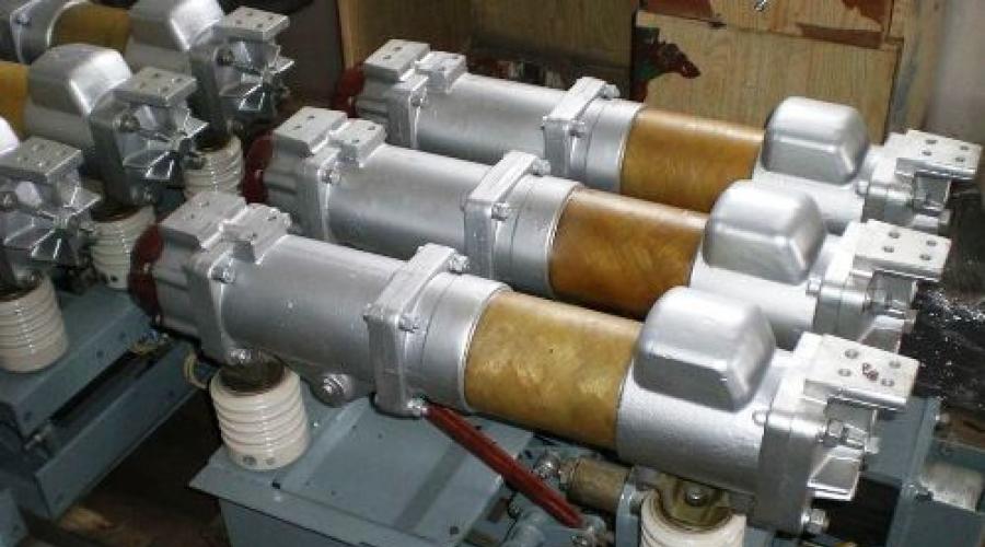
General form switches is shown in Fig. 1 and 2.
Each phase of the switch is mounted on its own cover and has a separate tank into which insulating oil is filled. The three phases of the switch are mounted on a common welded frame. The phase covers are connected by pipes. The frame contains a drum with a cable for lowering and raising the tanks. There is a winch on the drum shaft, and a cable is placed on the rollers of each tank. The location of the switch phase parts is shown in Fig. 3 and 4.
Rice. 1. General view of the VL1-35 switch.

Rice. 2. General view of the MKP-35 switch.
1 - cover; 2-tank 3 - input; 4 - frame; 5 - connecting pipe; 6- drum; 7 - winch; 8 - cabinet with drive.

Rice. 3. Section of the phase of the switch VL1-35.
1 - drive mechanism; 2 - oil indicator; 3 - guide pipe; 4 - screen; 5 - moving contact; 6 - oil drain valve; 7 - input; 8 - cover; 9 - current transformer; 10 - arc extinguishing chamber; 11 - tank; 12 - shaft;
13 - cotton wool bearing; 14 - connecting plug; 15 - input casing; 16- retaining ring; 17 - fixed contact; 18 - tank insulation.

Rice. 4. Section of the switch phase o
MKP-35.
1 - drive mechanism; 2 - oil indicator-1el; 3 - guide pipe; 1 - screen;
5 - moving contact; 6 -- MafocnvcK valve; 7-input, “-cover; 9-current transformer; 10 - arc-extinguishing chamber; 11 - tank; 12 - frame; 13 - lower part of the drive cabinet;
14 - plug through which a rod is screwed into the end of the rod when taking vibrograms of the speed of movement of the rod;
INSTRUCTIONS
operating instructions for circuit breaker S-35
Knowledge of this manual is required for:
- Head, foreman of a group of substations.
- Operational and maintenance personnel.
- Repair personnel of the group of substations and central electrical power stations.
The instructions are drawn up on the basis of the current "Rules" technical operation power stations and networks", "Rules for electrical installations", "Instructions for operation and repair of switches type C-35" from the manufacturer.
2. GENERAL INSTRUCTIONS. CRITERIA AND LIMITS OF SAFE CONDITION.
2.1 Type C-35 switches belong to multi-volume oil tank switches. Switches of this type were produced with rated current 630A and shutdown current 10 kA.
2.2 Switches are designed for switching high-voltage three-phase circuits alternating current in the nominal operating mode of the electrical installation, as well as for their automatic shutdown in case of short circuits and overloads that occur during emergency conditions.
2.3 Switches are designed to operate in a non-explosive and non-fire hazardous environment, not containing aggressive gases and vapors in concentrations that destroy metals and insulation and not saturated with conductive dust and water vapor in concentrations that prevent normal operation switch.
2.4 Working position switch in space - vertical.
2.5 Switches can be coupled with ShPE-12 or PP-67 drives
2.6 Switching resource - 4 disconnected short circuits.
2.7 Mechanical life - 50 cycles.
3. BASIC TECHNICAL DATA OF THE SWITCH.
4. DEVICE AND PRINCIPLE OF OPERATION OF THE SWITCH.
4.1 Switch S-35 refers to liquid three-pole high-voltage switches with a large volume of arc-extinguishing liquid - transformer oil.
4.2 The switch is a high-speed tank-type switch equipped with arc-extinguishing devices in the form of oil blast chambers.
4.3 The principle of operation of the C-35 circuit breaker is based on the extinguishing of an electric arc by the flow of a gas-oil mixture formed as a result of the intensive decomposition of transformer oil under the influence of high temperature arcs. This flow receives a certain direction in the oil blast chamber located in the arc burning zone.
4.4 The switch must be controlled remotely.
The operation of turning on the switch is carried out using energy magnetic field in an electromagnetic drive. The circuit breaker is tripped by the energy stored in the trip springs during the closing operation.
5. DEVICE AND PURPOSE OF MAIN PARTS.
5.1 Each phase of the C-35 circuit breaker is placed in a separate tank. All three phases are mounted on a common metal frame 6, are mechanically interconnected and controlled by an electromagnetic drive placed in a cabinet (see photo General view of the switch)
5.2 Each phase of the switch is equipped with a cast cover, which is the main part to which other parts are attached. The covers of the individual phases are rigidly connected to each other by means of intermediate couplings.
5.3 The cover contains fixed contact inputs, drive mechanisms, built-in current transformers, and moving contact guides.
A corner box is also attached to the cover of the first phase of the switch from the drive, designed to transmit movement from the drive to the mechanisms of individual phases. There is also a position indicator with the inscription " INCLUDED", "DISABLED".
5.4 The circuit breaker tanks have an oval-conical shape and are attached to the cover with bolts. Each tank is equipped with an oil level indicator, an oil drain valve and a device for heating the oil at low temperatures. Inner surface The tank has insulation made of 60 plywood with a thickness of 4 mm.
Lowering and raising the tanks is carried out using a common winch installed on the frame, a cable and a block system.
5.5 The switch is equipped with two gas outlets in the form of gas pipes attached to the interphase couplings. To prevent dust and moisture from entering the switch, the free ends of the gas outlet pipes are closed with spring-loaded valves.
5.6 Each phase of the switch is equipped with two inputs. The bushing is a capacitor mastic-filled bushing with a copper current-carrying rod with threads at the ends. A condenser bakelite sleeve is wound around the current-carrying rod. The upper part of the sleeve is covered with a porcelain cover, which has a developed surface in the form of ribs.
The tire is reinforced into a flange made of non-magnetic cast iron, mounted on the middle part of the bushing. The cavity between the condenser bakelite bushing and the porcelain cover is filled with bitumen filling mastic, which protects the bushing from moisture. The end of the tire is closed with a cast iron lid. The seal between the lid and the porcelain is achieved by using rubber washers mounted on the varnish. The cover is secured with a nut that is screwed onto the protruding end of the current-carrying rod, onto which a copper lug for connecting the busbar is also screwed and locked with two nuts. A thin-walled steel cap is soldered to the tip, which is additional protection input from moisture penetration.
The lower part of the inlet does not have a porcelain cover and is partially immersed in oil.
The protruding lower end of the current-carrying rod is intended for attaching a fixed contact.
5.7 To transmit movement from the drive to the arc chute, each phase of the C-35 circuit breaker is equipped with a drive mechanism. The drive mechanism of each phase is a system of levers forming the so-called rectifier and is assembled in a steel case placed under the cover of each phase.
5.8 The driving lever of the mechanism is pivotally connected to horizontal rods that connect the mechanisms of the individual phases to each other and receive movement from the drive. The shackle with the leading lever forms a system of links with a “dead center”. The straight rod, mounted on the shaft, has a hinged connection at one end with a shackle, and at the other end with a rocker arm, to which an insulating rod is suspended at a point, carrying a traverse with an arc-extinguishing chamber.
A guide pipe is attached to the bottom of the mechanism body, through which an insulating rod passes.
The drive mechanism of each phase is equipped with a tripping spring, which serves to speed up the shutdown process.
ARC DEVICE AND CONTACTS.
5.9. The arcing device of the C-35 circuit breaker is made in the form of a cross-slit oil blast chamber. The camera consists of the following main parts:
- a holder through which the camera is attached to the insulating rod;
- a housing capable of withstanding high pressure, the housing has a cavity to create an elastic gas cushion during the shutdown operation and is made of brass or bronze for 630 A switches;
- jumper, end type, reinforced in the body; The jumper can move in a vertical direction and is under the action of a spiral spring, which tends to press it upward.
- a set of insulating plates forming two horizontal slits, the plates are attached to the body using insulated steel bolts;
- side holes at the entry point of the contact rod it has insulating necks;
5.10. Fixed contacts are solid copper rods (candles) with replaceable tips. The contact rods are screwed into the block and secured to the input.
The traverses are suspended from the drive mechanism using insulating rods. To center the rods and prevent them from arbitrarily swinging during movement, bakelite guide pipes are installed.
The guide tubes have spring-oil buffers to absorb the energy of moving contacts and other moving parts switch at the end of the tripping stroke.
5.11. The principle of operation of the arc suppression chamber is as follows: when the contacts in the chamber open, an electric arc occurs between them. Under the influence of high temperature, the oil located in the arc action zone decomposes and pressure is created in the chamber body. When the contact rod moves downwards, slits open through which oil and gases are intensively pushed out. The gas-oil mixture cools the stretching arc, deionizes and extinguishes it. After the arc goes out, the gases remaining in the chamber are removed through an opening in the chamber, after which the chamber is again filled with oil.
Built-in current transformers.
5.12. The C-35 switch is equipped with built-in current transformers, made in the form of a ring core made of transformer steel with a secondary winding. The current-carrying input rod serves as the primary winding of the current transformer. Current transformers are put on the inputs and attached to the cover of each phase of the switch using metal flanges and studs.
For getting various coefficients transformations, the secondary windings of current transformers have branches. Ends of windings and branches
are output to terminals located directly at the current transformers,
and from here, using wiring, they are connected to the clamps located in the switch drive cabinet.
Device for heating oil.
5.13. To ensure normal operation of the circuit breaker in areas where the temperature environment can drop to minus 25 degrees C, it must be equipped with a device for heating the oil. 2 heating elements are installed under the bottom of the tank for each phase of the switch.
The elements can be powered from a 220 V network with a serial connection and 110 V with a parallel connection. The power required to heat the oil in a three-tank switch is 3600 W. The heating device should be switched on when the ambient temperature drops to minus 20 degrees C and switched off at minus 15 degrees C.
6. Preparing the circuit breaker for commissioning.
6.1. After completing installation or repair, it is necessary to carefully inspect the switch and drive:
- check the correctness and reliability of connecting the switch frame to the grounding circuit;
- check the reliability of the contacts on the busbar and the presence of temperature indicators;
- clean the surface of the switch from dust, wipe the insulating parts with a soft, clean cloth;
- check the presence of lubricant on the rubbing parts of the switch and drive;
- check the presence of oil and its level in all tanks of the circuit breaker;
- check serviceability and correct operation locking devices;
- check the presence of dispatch name inscriptions and their compliance with the requirements of the instructions;
- check the availability of records in the repair and technical documentation, in the journals “Equipment readiness after professional tests” and “Instructions for operating personnel on the readiness of relay protection and automation devices”;
6.2. Remove the crew from the workplace, close the work permit and hand over the equipment to the dispatcher;
7. Operation of the switch.
7.1. Personnel servicing switches must know the structure and operating principle of the device, know and comply with the requirements of this instruction;
7.2. All information about malfunctions detected during operation of the circuit breaker must be recorded in the "Log of defects and problems with equipment" and reported to the head of the substation group, and information about disconnected short circuits is recorded in the "Log of automatic shutdowns";
7.3. During operation, maintenance personnel are obliged to:
- ensure that the load current does not exceed the values specified in the table of section 3;
- inspect the circuit breaker within the time limits specified in the PTE; extraordinary inspections are carried out after the short circuits have been disconnected;
- after disconnecting 4 short circuits, the circuit breaker must be taken out for emergency repair;
- During external inspection, check:
- oil level in tanks and absence of oil leakage;
- condition of the insulators: surface cleanliness and absence of visible defects, cracks, smudges of filling mastic;
- no traces of oil release from gas outlets;
- absence of crackles and noises inside the tank, corona and discharges at the inputs;
- no heating contact connections;
- absence of melting on the busbar, caps and flanges of the inputs and on the switch cover;
- state mechanical fastenings switch and drive;
- compliance of the oil switch position indicators with its actual state;
- condition of secondary switching wiring and terminal rows;
- state of the grounding bus;
7.4 Mechanical characteristics during operation they must comply with the standards given in the table of section 3.
7.5 Current repairs must be carried out annually.
During routine repairs, the following work must be performed:
- checking the condition and tightening of bolted connections, including contact ones;
- checking the operation of the kinematics of the drive mechanism and drive;
- checking the condition of gas outlets
- cleaning and lubricating the drive with non-freezing lubricant (for example, GOI-54);
- checking the integrity and cleaning of insulators, oil level indicators and adjusting the oil level in tanks;
- tightening or replacing sealing gaskets;
- checking the serviceability of the oil heating device
7.6 Medium repairs are carried out 3 - 4 years after major repairs.
At the same time, a complex of works is carried out in the scope of current repairs and additionally the transition resistance and on- and off-speeds are measured. If these parameters turn out to be higher than normal, the circuit breaker will undergo an extraordinary overhaul.
7.7 Major repairs are carried out once every 6 - 8 years. Volume overhaul consists of the following main operations:
- draining oil, lowering tanks, repairing and cleaning tanks and fittings;
- repair of arc chutes, insulating rods and moving contacts
- inspection of the inputs, checking the tightness of the seals and the condition of the filling mastic;
- repair, inspection and adjustment of the drive mechanism and drive;
- repair of built-in current transformers and secondary switching circuits;
- adjustment of switch contacts;
- lifting tanks, filling them with oil, repairing other parts and painting the switch;
- preventive testing and acceptance of the circuit breaker from repair;
- preparation of repair and technical documentation;
8. Taking the circuit breaker out of operation, allowing for repairs and testing.
8.1 The circuit breaker is taken out for scheduled repairs upon application submitted within the established time frame. Output for emergency repair - according to an emergency application submitted immediately after detection of an emergency condition.
8.2 Repair of the circuit breaker at the installation site is carried out according to the work permit after the team has been admitted to the workplace prepared in accordance with the safety regulations.
8.3 The work manager must have an approved document at his workplace routing repair or work organization project.
8.4 The repair team may include insulation laboratory personnel to conduct high-voltage tests.
9. Safety measures when operating the switch.
9.1 When inspecting the circuit breaker, it is prohibited to penetrate mesh or barrier fences (in closed switchgear) and approach live parts at a distance less than permissible.
9.2 If, during inspection of the switch, a lack of oil is detected in the oil measuring glass of at least one phase or an oil leak that threatens an unacceptable decrease in the oil level, then this must be immediately reported to the dispatcher and the head of the substation group (substation), and the operating current must be removed from the switch control circuit for preventing its automatic or remote shutdown and damage. After this, emergency measures must be taken to remove him from work.
The energy industry has a lot on its hands big problem: Professionals born between the mid-1940s and mid-1960s are approaching retirement age. And a very big question arises: who will replace them?
Overcoming barriers to renewable energy use
Despite certain achievements in last years, energy from renewable sources makes up a very modest part modern services to provide energy around the world. Why is this so?
Real-time power transmission monitoring
The demand for electricity continues to grow and electricity transmission companies are faced with the challenge of increasing the transmission capacity of their networks. It can be solved by building new and modernizing old lines. But there is another solution, it involves the use of sensors and network monitoring technology.
Material that could make solar energy 'surprisingly cheap'
Solar cells, made from a long-established material that is cheaper than silicon, can generate the same amount of electrical energy as solar panels used today.
Comparison of SF6 and vacuum circuit breakers for medium voltage
Experience in the development of medium voltage circuit breakers, both SF6 and vacuum, has provided ample evidence that neither of these two technologies is, in general, significantly superior to the other. Decision-making in favor of one technology or another is stimulated by economic forces, user preferences, national “traditions”, competence and special requirements.
Medium voltage switchgear and LSC
Medium voltage switching equipment in metal case and loss of serviceability categories (LSC) - categories, classification, examples.
What factors will influence the future of transformer manufacturers?
Whether you produce or sell electricity or supply power transformers outside the country, you are forced to deal with competition in the global market. There are three main categories of factors that will influence the future of all transformer manufacturers.
The future of medium voltage switching equipment
Smart grids aim to optimize the connections between electricity supply and demand. During integration more distributed and renewable energy sources into one network. Is medium voltage switchgear ready to meet these challenges, or does it need to be further developed?
Looking for a replacement for SF6 gas
SF6 gas has a number of useful characteristics, used in various industries, in particular, actively used in the electricity sector high voltage. However, SF6 gas also has a significant drawback - it is a powerful greenhouse gas. It is one of the six gases included in the Kyoto Protocol.
Advantages and types of switchgear
It is advisable to place the electrical substation at the load center. However, often the main obstacle to such a substation placement is the space required for it. This problem can be solved through the use of switchgear technology.
Vacuum as an arc quenching medium
Currently, in medium voltage applications, vacuum arc extinguishing technology dominates over technologies using air, SF6 gas, or oil. Generally, vacuum circuit breakers are safer, and more reliable in situations where the number of normal and maintenance operations short circuits, very large.
Selecting a company and planning a thermal imaging survey
If the idea of thermal imaging inspection of electrical equipment is new to you, then planning, searching for a contractor, and determining the benefits that this technology can provide causes confusion.
The most famous methods of insulating high voltage
The seven most common and well-known materials used as high-voltage insulation in electrical structures. For them, aspects requiring special attention are indicated.
Five technologies for increasing the efficiency of power transmission and distribution systems
If you pay attention to measures that have highest potential In improving energy efficiency, electricity transmission inevitably comes first.
Self-healing networks are coming to Holland
Economic growth and population growth are leading to increased demand for electricity, coupled with stringent restrictions on the quality and reliability of energy supply, and increasing efforts to ensure grid integrity. In the event of a network failure, their owners are faced with the task of minimizing the consequences of these failures, reducing the time of failure and the number of consumers disconnected from the network.
The installation of high-voltage circuit breakers for each company involves significant investments. When the question arises about their maintenance or replacement, it is necessary to consider all possible options.
Ways to develop safe, reliable and efficient industrial substations
The main factors that should be taken into account when developing electrical substations for powering industrial consumers are considered. Attention is drawn to some innovative technologies, which can improve the reliability and efficiency of substations.
To compare the use of vacuum circuit breakers or contactors with fuses in distribution networks of voltage 6... 20 kV, it is necessary to understand the main characteristics of each of these switching technologies.
AC Generator Breakers
Playing an important role in the protection of power plants, generator circuit breakers enable more flexible operation and the ability to find effective solutions to reduce investment costs.
Looking through the switchgear
X-ray inspection can help save time and money by reducing the amount of work required. In addition, the time of supply disruptions and equipment downtime for the client is reduced.
Thermal imaging inspection of electrical substations
SF6 gas in the power industry and its alternatives
In recent years, environmental issues have become very heavy weight in society. SF6 gas emissions from switching equipment are a major contributor to climate change.
Hybrid switch
High voltage circuit breakers are important electrical power equipment used in power transmission networks to isolate the faulty section from the working part. electrical network. This ensures safe work electrical system. This article analyzes the advantages and disadvantages of these two types of switches, and the need for a hybrid model.
Safety and environmental friendliness of insulation of distribution equipment
The purpose of this article is to highlight the potential hazards to personnel and the environment associated with the same equipment, but not energized. The article concentrates on switching and distribution equipment for voltages above 1000 V.
Functions and design of medium and high voltage circuit breakers
Advantages of DC in high voltage lines
Despite the greater prevalence of alternating current in the transmission of electrical energy, in some cases the use of high voltage direct current is preferable.
Download document
MINISTRY OF ENERGY AND ELECTRIFICATION OF THE USSR
GLAVENERGOREMONT
MANAGEMENT
FOR OVERHAUL REPAIRS
OIL SWITCH
MKP-35-1000-25
RD 34.47.604
SERVICE OF EXCELLENCE FOR SOYUZTEKHENERGO
"Uralelektrotyazhmash" Glavenergoremont
A.I. Utkin V.I. KURKOVICH
1. Introduction
1.1. The manual for the overhaul of the oil switch MKP-35-1000-25* is technical document, compliance with the requirements of which is mandatory for personnel performing major repairs of the circuit breaker.
c) rules for accepting equipment for repair and repair;
d) quality assessment criteria repair work.
1.4. The manual was developed based on the technical documentation of the manufacturer.
2. Organization of work to repair the circuit breaker
2.1. General provisions
2.1.1. The composition of the team (link) for repairing the circuit breaker is established depending on the intended scope of work (the duration of repair work is determined by the network repair schedule).
2.1.2. The timing of repair work should be determined taking into account the following:
a) the composition of the team must correspond to the technological repair scheme. Changing the composition of the team until the repair is completed is not allowed;
b) continuous workload of individual performers and the team as a whole is ensured;
c) to ensure the completion of repair work within the established time frame, it is recommended to issue standardized task plans and use the aggregate-unit method of repair using the exchange stock of parts;
d) the work schedule of repair personnel should be subject to the maximum reduction in the duration of repair work.
2.1.3. The manual provides for a repair team of 4 people: electricians of the 5th category - 1 person, 3rd category - 2 people, 2nd category - 1 person.
2.1.4. Labor costs for overhaul of the circuit breaker are determined on the basis of the “Time Standards for Overhaul, current repairs and operational maintenance of equipment for substations 35 - 500 kV and distribution networks 0.4 - 20 kV", approved by the USSR Ministry of Energy in 1971.
Standards for overhaul of oil switch MKP-35-1000-25 (without changing inputs) - 41.8 man-hours, with changing inputs - 52 man-hours.
2.2. Preparation for repair
2.2.1. Preparation for major repairs is carried out in accordance with the specific scope of work provided for this type of equipment.
2.2.2. Before the start of repairs, a team of workers with appropriate qualifications who have undergone training, knowledge testing and instructions on the rules is staffed safe management works
2.2.3. Before starting work, the team is given a planned task with a specific list of work and an indication of its volume, labor costs and completion date, as well as technological instructions and requirements.
2.2.4. Before starting repairs you must:
a) prepare a set metalworking tools, as well as instruments and measuring instruments (Appendices 1, 2);
b) prepare basic and auxiliary materials, spare parts for repairs (Appendices 3, 4); The list and quantity of materials should be specified in accordance with the scope of work;
c) prepare and check protective equipment;
d) coordinate the work procedure with other teams performing related work.
2.2.5. The performers, together with the repair manager, after drawing up a general work order for the repair of the circuit breaker, must:
a) make sure that it is correct and full implementation all measures to ensure work safety;
b) carry out all fire safety measures.
2.3. Quality control of repair work
2.3.1. Quality control of repair work by the contractor is carried out in the following order:
a) check, together with the repair manager, the condition of each assembly unit during the repair. In this case, the manager must give instructions on the methods of repair and supplement, (clarify) the technical requirements for repair, according to which the assembly unit will be accepted from repair and the quality of repair work will be assessed;
b) finished hidden work and present the completed intermediate operations to the manager for acceptance and quality assessment;
c) after completing all repair work, present the circuit breaker for final acceptance.
2.3.2. Final acceptance of the product as a whole is carried out by representatives of the operational department together with the repair manager, about which a document is drawn up technical act repair, which is signed by representatives of both parties.
3. Acceptance of the circuit breaker for repair
3.1. Before the start of a major overhaul, a commission of representatives of the operational and repair departments, with the obligatory participation of the repair manager, checks the state of readiness for repair:
a) availability of a statement of the volume of capital repair work;
b) availability of materials, spare parts, special equipment and tools;
c) the state of safety measures, labor protection and fire safety;
d) availability of a capital repair schedule.
3.2. When accepting the circuit breaker for repair, it is necessary to familiarize yourself with the list of defects and the scope of work performed during the previous major overhaul and during the period between repairs.
Technical data of the oil switch MKP-35-1000-25
(meets the requirements of GOST 687-70)
Voltage, kB:
nominal 35
highest working 40.5
Rated current, A 1000
Limit through current, kA:
effective value of periodic component 25
amplitude 63
Limit thermal stability current, kA 25
Rated shutdown current, kA 25
Shutdown power, MV-A 1750
Thermal stability current flow time, s 4
Permissible number of short circuit trips without circuit breaker inspection 5
Weight, kg:
switch with drive (without oil) 2750/2830
drive 310
transformer oil 800
Technical data of the electromagnetic drive PE-31
(meets the requirements of GOST 688-67)
Nominal voltage of the electromagnet, V:
including 110/220
disconnecting 110/220
Limits operational work drive by voltage at the terminals of its windings, % rated:
closing electromagnet 85 - 110
disconnecting electromagnet 65 - 120
Current consumption of the electromagnet winding at an ambient temperature of 20 °C, A:
including 248/124
disconnecting 10/5
Current consumption of the contactor switching winding at a voltage of 110/220 V, A 2/1
Resistance of electromagnet windings, Ohm:
including (one section) 0.85 - 0.92
disconnecting (one section) 20.25 - 23.75
4. Disassembling the switch
4.1. General instructions for defecating the circuit breaker
4.1.1. Inspect the switch, make sure there are no oil leaks. If there is a leak, determine the cause.
4.1.2. Check that the switch frame is installed correctly and its upper base is horizontal.
4.1.3. Inspect the fastening of the frame to the foundation (anchor bolts must have locknuts). The frame must be reliably grounded with a steel strip with a cross-section of at least 25×4 mm.
4.1.4. Check the condition of the winch and cable.
4.1.5. Make sure the safety valve rupture screw is intact.
4.1.6. Carry out several test switches on and off; determine the preliminary scope of repairs.
4.2. Disassembly and assembly of bushings that cannot be replaced
4.2.1. Disconnect the tires.
4.2.2. Unscrew the locking screws 2 (Fig. 1), unscrew the nuts 1 and the cap with tip 3.
4.2.3. Unscrew the locking screw II from the nut 10, remove the gasket (brass washer) 4, the centering washer 5 and the gasket 6.
Note. Work according to clause 4.2 should be carried out with the switch in the on position in order to avoid turning the current-carrying rod 9 in the capacitor sleeve 8.
4.2.4. Unscrew the nuts. Remove casing 7.
4.2.5. Carry out fault detection of inputs in accordance with clause 6.8.
4.2.6. Install casing 7, screw on the nuts.
4.2.7. Install rubber gasket 6, centering washer 5, gasket (brass washer) 4, screw in nut 10, screw in locking screw 11.
4.2.8. Screw on the cap with tip 3, nuts 1 and screw in locking screws 2.
4.3. General operational disassembly of the circuit breaker
4.3.1. Drain the oil from the switch tanks into a previously prepared container. Check the operation of the oil indicators.
4.3.2. Turn off the oil heating device in the tanks.
4.3.3. Place the cable on the rollers 3 of the tank (Fig. 2), and pull it lightly. Unscrew the nuts from the bolts securing the tank, remove the washers, lower tank 1 until the cable is completely loosened, remove the cable from the tank rollers. The tanks of the other two phases are lowered similarly.
4.3.4. Unscrew the bolts securing screen 1 (Fig. 3), lower the screen until it stops against the traverse.
4.3.5. Unscrew the bolts securing the housing 2 to the holder 3, lower the housing with the camera.
4.3.6. Lift the screen and put it on bottom part bakelite input bushing. Take out the body and camera, then remove the screen.
4.3.7. Disconnect the outer and inner ends connected to current transformer 2 (see Fig. 2). Check for markings first. If not available, apply.
4.3.8. Unscrew the nuts and remove the current transformers.
Note. Only remove current transformers when they need to be replaced or dried.
4.3.9. Unscrew the nuts from the input bolts, remove the input and gasket (dismantle the input only if necessary).
5. Preparation for defect detection and repair
5.1. Thoroughly clean the components and parts from dirt, old lubricant residues and corrosion-mechanical wear products, rinse in B-70 gasoline and dry for inspection and identification of defects.
5.2. Remove traces of corrosion, varnish, and paint with sandpaper, cleaning these areas to a metallic shine.
6. Technical requirements for defect detection and repair of circuit breaker parts and assemblies
6.1. Bolts, studs, nuts, threaded connections are subject to rejection if:
a) cracks;
b) dents, nicks, chipping of more than two turns;
c) the bent of the bolt (stud) is more than 1 mm per 100 mm of length.
6.1.1. Edges and corners on bolt heads and nuts should not be crushed or cut off. If the edges are worn more than 0.5 mm (from the nominal size), the bolt or nut is rejected.
6.1.2. Holes for cotter pins in bolts and studs should not be clogged and should be noticeably enlarged.
6.1.3. When disassembling, serviceable studs should not be removed from parts. A tight and tight fit of the studs is checked by tapping. If a rattling sound is heard, then the pin should be unscrewed and the fit restored.
6.2. Shafts, axles.
6.2.1. Axles must be replaced if:
a) wear in diameter, ovality in places of wear;
b) axial curvature of more than 0.2 - 0.3 mm;
c) cracks, scuffs on the friction surfaces of shafts and axles;
d) saddles on the working friction surfaces of shafts and axles.
6.2.2. Shafts and axles should be straightened in a cold state with light blows of a hammer on a stable support. To prevent damage to parts, place wooden or lead spacers on the support and under the hammer. Check the curvature using a plumb line.
6.2.3. It is allowed to reduce the shaft, axle and ellipse of the part at the wear site by no more than 0.4 mm; check the diameter and ellipse of the shafts and axes with a micrometer.
6.2.4. It is allowed to increase the diameter of the holes and their ellipse by no more than 0.4 mm. Check the diameter and ellipse of the hole with a caliper.
6.2.5. Remove burrs on the surfaces of the axles carefully with a fine file or sandpaper.
6.2.6. Saddles and dents on the working surfaces of the axles are determined by measuring the smallest diameter in deformed areas. Filing of saddles and dents on working surfaces is not allowed.
6.3. Lock washers and spring washers must be discarded:
a) in the presence of cracks and fractures;
b) with loss of elasticity;
c) if the spread of the spring washers is less than one and a half of its thickness.
6.3.1. The normal spread of the washer is equal to twice its thickness, the acceptable one is one and a half.
6.3.2. If the fit is loosened or the alignment pins are worn, expand the hole under them and install repair size pins.
6.4. Cylindrical coil springs are subject to rejection if:
a) cracks and breaks;
b) uneven pitch of coils along the entire length of the spring of more than 10%;
c) deviations of the spring axis from the perpendicular to the end plane of more than 5 mm per 100 mm of length;
d) loss of spring elasticity is allowed within 5 - 10% of the normal value.
6.5. Seals.
6.5.1. Self-clamping oil seals are subject to rejection if:
a) dents, deep scratches and other mechanical damage to the body and cover;
b) cracks, cuts, tears, deep scratches on the surface of the cuff in contact with the shaft;
c) loose fit of the oil seal seal in the housing;
d) breakage or damage to the spring.
6.5.2. All felt seals and seals must be replaced during major repairs.
6.6. Sealing gaskets.
6.6.1. Cardboard gaskets should not have any torn spots or tears.
6.6.2. The uneven thickness of the gasket should not exceed 0.1 mm along the entire length.
6.6.3. The surface of the gasket must be smooth, clean, without folds or wrinkles.
6.6.4. Rubber gaskets should not have cracks, shear, or residual deformation. If the listed defects are present or there is loss of elasticity, replace the gasket.
6.7. Current transformers
6.7.1. Measure the insulation resistance of the secondary winding with a megohmmeter for a voltage of 1000 V. The insulation resistance of the secondary winding with connected secondary circuits must be at least 1 MOhm.
6.7.2. Check the condition of insulation surfaces. Wrap the damaged areas with keeper tape, varnish with bakelite varnish, and dry.
6.8. Technical requirements for defect detection and repair of circuit breaker assembly units.
6.8.1. Movable contact
Quantity per product - 3.
1. Cracks and deformation are not allowed.
3. After filing, indentations of no more than 0.5 mm are allowed.
6.8.2. Capacitor input (Fig. 1)
Quantity per product - 6.
|
Position in the picture |
Possible defect |
Method for eliminating the defect |
|
|
Cracks, chips with total area whiter than 10 cm 2 |
Inspection. Measurement. Ruler |
Replace |
|
|
The same area up to 10 cm 2 |
Inspection. Measurement. Ruler |
Clean, degrease, coat with a layer of bakelite varnish |
|
|
Oxidation, carbon deposits |
Clear |
||
|
Partial chipping of the putty of the reinforcement joints |
Finish with subsequent varnish coating |
||
|
Cracks, peeling of mastic from the walls |
Replace |
Technical requirements for the repaired part
1. The insulation resistance must be at least 1000 megohms.
2. Dielectric loss tangent tgd should be no more than 3% (at a temperature of 20 × 5 °C).
3. The bushing must withstand the high voltage test of 95 kV for 5 minutes.
4. Ohmic input resistance is no more than 60 μOhm.
6.8.3. Arc chamber (Fig. 3)
Quantity per product - 6.

|
Position in the picture |
Possible defect |
Method for identifying a defect and control tool |
Method for eliminating the defect |
|
Burning, melting and shells |
File down, maintaining the original shape. Sinkholes on the contact surface with a depth of no more than 0.5 mm are allowed. Restore silver coating using electric spark method |
||
|
Warping and burning of insulating plates |
Replace |
||
|
Burnout of more than 2/3 of the compound layer |
Replace |
||
|
More than 1/4 of the thickness of the flexible connection package is broken |
Replace |
Technical requirements for the repaired part
1. Cracks and deformations are not allowed.
2. Breaking the thread on more than one turn is not allowed.
3. Torn sheets If there is a break less than 1/4 of the thickness, cut off.
6.8.4. Tank (item 1 fig. 2)
Quantity per product - 3.

|
Position in the picture |
Possible defect |
Method for identifying a defect and control tool |
Method for eliminating the defect |
|
Oil indicator leaking |
Replace the defective part, clean the oil indicator glass |
||
|
Significant warping of in-tank insulation |
Inspecting a tank that is not filled with oil |
Replace |
|
|
Eliminate by editing |
|||
|
Cracks in welds |
Inspecting the oil-filled tank |
Eliminate with tea leaves |
|
|
Damage to anti-corrosion coating |
Clean damaged areas, degrease, restore coating |
||
|
Oil drain valve leaking |
Coat with putty and paint with oil paint |
Technical requirements for the repaired part
Cracks and deformations are not allowed.
7. Assembly components switch
7.1. Installation of entries
7.1.1. Place the gasket on the cover hole under the input flange, lift the input onto the switch, carefully install it into the cover hole, center until the axes of the mounting holes coincide. Finally adjust the input position. Secure the inlet to the cover with bolts and nuts and washers. To avoid transfer, tighten the nuts alternately diagonally.
7.2. Assembly of arc extinguishing device and contact system
7.2.1. Secure to holder 3 (see Fig. 3) and fixed contact 6 flexible connections 4. Make sure that the ends of the bolts securing the flexible connections do not go inside the annular recess of the cup in which the spring 5 is located.
7.2.2. Install spring 5, screw in the guide bolt. Make sure that the cuts of the bolt head are located opposite the holes in the wall of the brass glass.
7.2.3. Install housing 2, secure with bolts to holder 3.
7.2.4. Assemble a set of insulating plates 7, secure them to the body with 2 insulated bolts.
7.2.5. Lift the screen and place it on the bottom of the bakelite bushing.
7.2.6. Install the camera onto the current-carrying input rod and secure it using pads and bolts.
7.2.7. Check the camera installation dimensions:
Deviation from the vertical ± 1 mm at the full height of the camera;
The distance from the camera to the axis of the guide pipe is within 90 ± 1 mm.
In this case, the moving contacts must move in the chamber without touching its walls.
Adjustment is made by changing the position of the camera on the current-carrying rod.
7.2.8. Fix the position of the camera on the current-carrying input rod with a locking screw.
7.2.9. Place screen 1 on the camera and secure it with bolts.
8. Switch adjustment
8.1. Check the operation of the drive mechanism. Turn on the switch slowly using a DV-33 jack. At the same time, check whether there are any areas where the moving system is stuck and an increase in the muscular effort required to turn on is felt. During the switching process (during the entire stroke), loosen the force on the jack handle several times, creating the possibility of reverse motion of the moving system.
Check whether the moving system of the switch will stop (freeze) in any intermediate position.
8.2. Check the correct position of the drive mechanism levers using a template (Fig. 4).
At correct position The levers of the drive mechanism axis must touch the template. An undershoot of the middle axis relative to the template line by 2 - 3 mm is allowed.
Attention! The transition of the middle axis beyond the template line towards the thrust pin is not allowed.
8.3. Non-compliance with the axle position pattern can be adjusted by shortening or lengthening the rods between the drive mechanisms of different phases by screwing in their tips.
If there is an equal discrepancy between the pattern of all three phases, adjustment should be made by changing the length of the vertical rod going to the drive.
8.4. Check the gap (1.5 - 2 mm) between the drive mechanism lever and the thrust pin.
Adjust the position of the stop pin in the on position of the switch.
8.5. Check the full stroke of the moving contact.
With the switch in the “on” position, make a mark on the rod at the lower end of the guide pipe. Turn off the switch and mark the rod again.
The full stroke of the rod is 270 - 280 mm.
8.6. Check the simultaneous closure of the pole contacts (discrepancy of no more than 2 mm is allowed), the closure of contacts between poles (divergence of no more than 4 mm).
Adjust:
a) lowering or raising cameras with fixed contacts;
b) screwing or unscrewing the movable contacts (rods) in the traverse liners.
8.7. Measure the contact resistance of each pole (no more than 300 μOhm). Measure with the secondary winding of the current transformers closed to the operating load or short-circuited.
8.8. Take a vibration record, check the speed of movement of the moving contacts of the switch (without oil) when turning off and on:
at the moment of contact opening - 1.7 - 2.3 m/s and 1.8 - 2.6 m/s; maximum - 3.0 - 3.6 m/s and 2.1 - 5.9 m/s, respectively.
It is recommended to check simultaneity, travel in contacts (pressure - 16 ± 1 mm), and take speed and time characteristics using the remote control (Fig. 5).
9. Drive repair
9.1. Drive Inspection
9.1.1. Clean and inspect all accessible parts of the drive from dust, dirt and old grease, check:
a) the condition of the axles and springs;
b) drive mount;
c) degree of corrosion of parts;
d) absence of dents and hardening on working surfaces.
Carry out defect detection and repair of drive parts in accordance with Section. 6.
9.1.2. Check for distortion and jamming of the electromagnet cores.
9.1.3. Pay attention to the reliability of the connections and their fastening.
9.1.4. Convert Special attention for the presence in all links of transmission mechanisms of devices that prevent spontaneous unscrewing (lock nuts, spring washers, etc.).
9.1.5. Inspect the block contacts KBO and KKB. Pay attention to the condition of the moving and fixed contacts, springs, clamps, contact screws, rods and levers.
9.1.6. Specify the final scope of drive repair. Disassemble the drive only if faults are detected that interfere with further normal operation of the drive.
9.2. Drive regulation
Attention! To avoid injury in the event of accidental shutdown during drive adjustment, it is necessary to screw the safety bolt 6 (Fig. 6) all the way to the shutdown pawl 5. When shutting down or completing the adjustment, unscrew bolt 6, setting the gap to 13 - 15 mm.
9.2.1. Maintain gaps and recesses of pawls in accordance with Fig. 6. Adjust the drop value of 5 - 8 mm of the disconnecting pawl 5 with bolt 2 and screw 4.
9.2.2. Check the reliability of the engagement of lever 3 with the latch when the release pawl 5 rests on bolt 6. Adjust with bolt 1.
9.2.3. Check that the position of the KBB and KBO contacts corresponds to the position of the switch. The on position of the switch must correspond to the off position of the KBB contact and the on position of the KBO contact.
9.2.4. Check the opening of the KBV block contacts at the end of the drive switching stroke. The test is carried out at a minimum voltage (93.5/187 V) at the terminals of the switching electromagnet at the moment of switching on.
9.2.5. Adjust the gap between the pawls and ratchets at the block contacts in accordance with Fig. 7. Adjustment is made by moving the fork 4 (Fig. 8) along the rod 3 and moving the threaded pin 2. The fork 4 should rotate on the rod 3.
Attention! To avoid damage to the transmission links of the block contacts, be careful when adjusting and attach the rod to the levers only after first checking its length in both extreme positions of the drive.
9.2.6. Coat the core of the switching electromagnet with a special lubricant (one part CIATIM-203 and one part amorphous or silver graphite).
10. Final assembly and testing of the circuit breaker
10.1. Clean the tank from dirt, wipe it, check the serviceability of the internal insulation.
10.2. Check the serviceability of the oil drain valves and electric heating. Turn on the tubular heaters at a voltage equal to 50% of the nominal voltage for 2 hours - for drying.
10.3. Install a removable winch, put the winch cable on the tank rollers 3 (see Fig. 2) and use the winch to lift the tanks and secure them.
10.4. Measure the shaft rotation angle, which should be 57°.
10.5. Fill the tanks with oil, the breakdown voltage of which is not lower than 35 kV. When filling, check the operation of the oil indicators and check for leaks. After filling and settling the oil, take a sample. The breakdown voltage of the oil must be at least 30 kV.
10.6. Paint the switch.
10.7. Connect tire deflations.
10.8. Define lowest voltage a closing electromagnet, in which the drive is able to turn on the switch idle.
10.9. Determine the lowest voltage of the tripping electromagnet at which the drive is able to trip the circuit breaker.
10.10. Check working together a switch with a drive that turns the switch on and off five times.
10.11. Before commissioning, test the switch with a voltage of 95 kV for 1 minute.
Annex 1
List of tools required for overhaul of the circuit breaker
|
Name |
Designation |
Standard designation |
Quantity, pcs. |
|
|
1. Open-end wrenches, double-sided: |
||||
|
Key 7811-0003 |
||||
|
Key 7811-0021 |
||||
|
Key 7811-0022 |
||||
|
Key 7811-0023 |
||||
|
Key 7811-0025 |
||||
|
2. Open-end wrenches, single-sided: |
||||
|
Key 7811-0142 |
||||
|
Key 7811-0146 |
||||
|
3. Pipe lever wrench No. 1 |
||||
|
4. Combination pliers, 200 mm long |
Pliers, 200 |
|||
|
5. Flat, blunt-nosed file |
File 2820-0029 |
|||
|
File 2820-0029 |
||||
|
6. Screwdriver for mechanics |
Screwdriver 7810-0309 |
|||
|
7. Bench hammer, steel, weighing 400 g |
Hammer 7850-0034 |
|||
|
8. Metric measuring ruler |
Line 1-500 |
|||
|
Line 1-150 |
||||
|
9. Vernier caliper |
||||
|
10. Bar level |
Level 150 mm long |
|||
|
13. Manual jack |
||||
|
14. Device for taking vibrograms |
||||
|
15. Template |
||||
|
16. Electric drill |
||||
|
17. Drills with a diameter of 6; 8 mm |
||||
|
18. Taps |
||||
Appendix 2
List of devices used during repairs
|
Name and designation |
Purpose and brief description |
|
1. Portable bridge - MD-16 |
Device for measuring capacitance and dielectric loss angle tgd |
|
2. Megaohmmeter M-1101 |
1000 V insulation resistance measurement |
|
3. Microohmmeter M-246 |
Measuring contact resistance |
|
4. Vibrograph |
Vibrogram removal, 12 V |
|
5. Voltmeter E-L5 |
0-600 V, class 0.5 |
|
6. Switch adjustment panel. Development of the Yuzhenergoremont enterprise |
Checking the simultaneous closure of contacts of a pole and between poles, taking characteristics, power supply of a vibrograph, lighting |
|
7. Installation for silvering by electrospark method EFI-54 |
Restoration of silver-plated contact surfaces (in the workshop only). The thickness of the applied layer is 0.01 mm. Maximum productivity up to 10 cm 2 /min |
|
8. Folding pocket magnifying glass LP-1-7* |
|
|
9. RSPS dual resistor |
340 ohms ± 10% 1 A - in series 2 A - parallel |
Appendix 3
Standards for material consumption for major repairs of a circuit breaker
|
Name |
Standard designation |
Consumption rate for repairing one circuit breaker |
|
Transformer oil TKp, kg |
||
|
Grease CIATIM-203, kg |
||
|
Aviation gasoline B-70, l |
||
|
Wiping rags, kg |
||
|
Sanding paper, different, m 2 |
||
|
Paint yellow, red, green, gray, kg |
Of necessity |
|
|
Electrical insulating cardboard EM, 1 mm thick, kg |
||
|
Technical sheet rubber, kg: |
||
|
Bakelite varnish, kg |
||
|
Different cotter pins, kg |
||
|
Drying oil oxol, kg |
||
|
Putty, kg |
||
|
Tow, kg |
||
|
Red lead, kg |
||
|
Keeper tape |
Appendix 4
Spare parts kit available upon special order
Appendix 5
List of main indicators of the technical condition of the circuit breaker after major repairs
Power system (REU) _________________________________________________
Company _________________________________________________
Statement
key indicators technical condition circuit breaker after major repairs
Type ______________________ Manufacturer __________________________
Serial number _______________________ Year of manufacture ________________
Reason for repair ________(scheduled, extraordinary, after shutdown_________
maximum number of short circuits)______________________________
_____________________________________________________________________
Start of repairs ____________________________ (date of)
Completion of repairs _________________________ (date of)
1. List of overhaul of circuit breaker assembly units (to be completed for assembly units that required replacement or overhaul of parts)
2. Switch adjustment
|
Characteristic |
Measurement results |
|||
|
Full stroke of moving contacts, taking into account the stroke in the buffer, mm |
||||
|
Stroke in contacts (pressing), mm |
||||
|
Different times of pole contact closure, mm, no more |
||||
|
Different times of contact closure between poles, mm, no more |
||||
|
Transition resistance of the current-carrying circuit, μOhm, no more |
||||
3. Testing a switch with an electromagnetic drive
|
Characteristic |
Measurement results |
|||
|
Minimum switching voltage at the terminals of the switching coil, V, no more |
||||
|
Resistance of one section of the switching coil, Ohm |
||||
|
Resistance of one section of the trip coil, Ohm |
||||
|
Speed of moving contacts, m/s |
||||
|
at the moment of opening |
||||
|
maximum |
||||
|
Speed of moving contacts |
||||
|
when turned on and there is no oil in the tanks (at the moment the contacts close, maximum) Rice. 8. Transmission from the drive shaft to high-speed contact blocks: 1 - shaft; 2 - finger; 3 - traction; 4 - fork
| ||||