Lm317 switching circuit with 12V adjustment. LM317 voltage stabilizer. LM317 regulated power supply circuit
The LM317 adjustable three-terminal current regulator provides a load of 100 mA. The output voltage range is from 1.2 to 37 V. The device is very easy to use and requires only a pair of external resistors to provide the output voltage. Plus, the instability in terms of performance indicators has better parameters than similar models with a fixed output voltage supply.
Description
LM317 is a current and voltage stabilizer that operates even when the ADJ control pin is disconnected. During normal operation, the device does not need to be connected to additional capacitors. The exception is when the device is located at a considerable distance from the primary filter supply. In this case, you will need to install an input shunt capacitor.
The output analog allows you to improve the performance of the LM317 current stabilizer. As a result, the intensity of transient processes and the value of the pulsation smoothing coefficient increase. Such an optimal indicator is difficult to achieve in other three-terminal analogues.
The purpose of the device in question is not only to replace stabilizers with a fixed output indicator, but also for a wide range of applications. For example, the LM317 current stabilizer can be used in high-voltage power supply circuits. In this case, the individual system of the device affects the difference between the input and output voltage. The operation of the device in this mode can continue indefinitely until the difference between the two indicators (input and output voltage) exceeds the maximum permissible point.

Peculiarities
It is worth noting that the LM317 current stabilizer is convenient for creating simple adjustable pulse devices. They can be used as a precision stabilizer by connecting a fixed resistor between the two outputs.
The creation of secondary power supplies that operate during short-term short circuits became possible thanks to the optimization of the voltage indicator at the control output of the system. The program keeps it at the input within 1.2 volts, which is very low for most loads. The LM317 current and voltage stabilizer is manufactured in a standard TO-92 transistor core, operating temperatures range from -25 to +125 degrees Celsius.
Characteristics
The device in question is excellent for designing simple regulated blocks and power supplies. In this case, the parameters can be adjusted and specified in terms of load.
The adjustable current stabilizer on the LM317 has the following technical characteristics:
- The output voltage range is from 1.2 to 37 volts.
- Maximum load current is 1.5 A.
- There is protection against possible short circuit.
- The circuit is protected against overheating.
- The output voltage error is no more than 0.1%.
- Integrated circuit housing - type TO-220, TO-3 or D2PAK.

Current stabilizer circuit on LM317
The device in question is most often used in LED power supplies. The following is a simple circuit that involves a resistor and a microcircuit.
The input voltage is supplied by the power source, and the main contact is connected to the output analogue using a resistor. Next, aggregation occurs with the anode of the LED. The most popular current stabilizer circuit, LM317, described above, uses the following formula: R = 1/25/I. Here I is the output current of the device, its range varies between 0.01-1.5 A. The resistor resistance is allowed in sizes 0.8-120 Ohms. The power dissipated by the resistor is calculated by the formula: R = IxR (2).
The information received is rounded up. Fixed resistors are produced with a small spread of final resistance. This affects the receipt of calculated indicators. To resolve this problem, an additional stabilizing resistor of the required power is connected to the circuit.
Advantages and disadvantages
As practice shows, during operation it is better to increase the dispersion area by 30%, and in the low convection compartment - by 50%. In addition to a number of advantages, the LM317 LED current stabilizer has several disadvantages. Among them:
- Low efficiency.
- The need to remove heat from the system.
- Current stabilization over 20% of the limit value.
The use of pulse stabilizers will help to avoid problems in operating the device.
It is worth noting that if you need to connect a powerful LED element with a power of 700 milliamps, you will need to calculate the values using the formula: R = 1.25/0.7 = 1.78 Ohm. The dissipated power will accordingly be 0.88 watts.

Connection
The calculation of the LM317 current stabilizer is based on several connection methods. Below are the basic diagrams:
- If you use a powerful transistor like Q1, you can get an output current of 100 mA without a microassembly heatsink. This is quite enough to control the transistor. As a safety net against excess charge, protective diodes D1 and D2 are used, and a parallel electrolytic capacitor performs the function of reducing extraneous noise. When using transistor Q1, the maximum output power of the device will be 125 W.
- Another circuit ensures current limitation and stable operation of the LED. A special driver allows you to power elements from 0.2 watts to 25 volts.
- The next design uses a step-down transformer from an alternating network from 220 W to 25 W. Using a diode bridge, the alternating voltage is transformed into a constant value. In this case, all interruptions are smoothed out by a capacitor of type C1, which ensures stable operation of the voltage regulator.
- The following connection diagram is considered one of the simplest. The voltage comes from the secondary winding of the transformer at 24 volts, is rectified when passing through the filter, and the output is a constant reading of 80 volts. This avoids exceeding the maximum voltage supply threshold.
It is worth noting that a simple charger can also be assembled based on the microcircuit of the device in question. You will get a standard linear stabilizer with an adjustable output voltage. The microassembly of the device can function in a similar role.

Analogs
The powerful stabilizer on the LM317 has a number of analogues in the domestic and foreign markets. The most famous of them are the following brands:
- Domestic modifications of KR142 EH12 and KR115 EH1.
- Model GL317.
- Variations of SG31 and SG317.
- UC317T.
- ECG1900.
- SP900.
- LM31MDT.
Hello. I bring to your attention a review of the integrated linear adjustable voltage (or current) stabilizer LM317 at a price of 18 cents apiece. In a local store, such a stabilizer costs an order of magnitude more, which is why I was interested in this lot. I decided to check what was being sold at that price and it turned out that the stabilizer was quite high quality, but more on that below.
The review includes testing in voltage and current stabilizer mode, as well as checking overheat protection.
For those interested, please...
A little theory:
There are stabilizers linear And pulse.Linear stabilizer is a voltage divider, the input of which is supplied with an input (unstable) voltage, and the output (stabilized) voltage is removed from the lower arm of the divider. Stabilization is carried out by changing the resistance of one of the divider arms: the resistance is constantly maintained so that the voltage at the output of the stabilizer is within the established limits. With a large ratio of input/output voltages, the linear stabilizer has low efficiency, since most of the power Pdis = (Uin - Uout) * It is dissipated as heat on the control element. Therefore, the control element must be able to dissipate sufficient power, that is, it must be installed on a radiator of the required area.
Advantage linear stabilizer - simplicity, lack of interference and a small number of parts used.
Flaw- low efficiency, high heat generation.
Switching stabilizer voltage is a voltage stabilizer in which the regulating element operates in a switching mode, that is, most of the time it is either in a cutoff mode, when its resistance is maximum, or in a saturation mode - with minimal resistance, which means it can be considered as a switch. A smooth change in voltage occurs due to the presence of an integrating element: the voltage increases as it accumulates energy and decreases as it is released into the load. This mode of operation can significantly reduce energy losses, as well as improve weight and size indicators, but it has its own characteristics.
Advantage pulse stabilizer - high efficiency, low heat generation.
Flaw- a larger number of elements, the presence of interference.
Review Hero:
The lot consists of 10 microcircuits in a TO-220 package. The stabilizers came in a plastic bag wrapped in polyethylene foam.


Comparison with probably the most famous linear stabilizer 7805 for 5 volts in the same housing.


Testing:
Similar stabilizers are produced by many manufacturers, here.
The position of the legs is as follows:  1 - adjustment;
2 - exit;
3 - entrance.
We assemble a simple voltage stabilizer according to the diagram from the manual: 

 Here's what we managed to get with 3 positions of the variable resistor:
  The results, frankly speaking, are not very good. I wouldn't dare call it a stabilizer.
Next, I loaded the stabilizer with a 25 Ohm resistor and the picture completely changed: 
Next, I decided to check the dependence of the output voltage on the load current, for which I set the input voltage to 15V, set the output voltage to about 5V using a trimmer resistor, and loaded the output with a variable 100 Ohm wirewound resistor. Here's what happened:  It was not possible to obtain a current of more than 0.8A, because The input voltage began to drop (the power supply is weak). As a result of this testing, the stabilizer with the radiator heated up to 65 degrees:
To check the operation of the current stabilizer, the following circuit was assembled: 

 Instead of a variable resistor, I used a constant one, here are the test results:
  Current stabilization is also good.
Well, how can there be a review without burning the hero? To do this, I reassembled the voltage stabilizer, applied 15V to the input, set the output to 5V, i.e. 10V dropped on the stabilizer, and loaded it at 0.8A, i.e. 8W of power was allocated to the stabilizer. The radiator was removed.
The result was demonstrated in the following video:
Yes, the overheating protection also works; it was not possible to burn the stabilizer.
Result:
The stabilizer is fully operational and can be used both as a voltage stabilizer (subject to the presence of a load) and as a current stabilizer. There are also many different application schemes for increasing the output power, using it as a charger for batteries, etc. The cost of the subject is quite reasonable, considering that offline I can buy such a minimum for 30 rubles, and in for 19 rubles, which is significantly more expensive than the one being reviewed .With that, let me take my leave, good luck!
The product was provided for writing a review by the store. The review was published in accordance with clause 18 of the Site Rules.
I'm planning to buy +37 Add to favorites I liked the review +59 +88The LM317 adjustable three-terminal positive voltage regulator provides 100 mA load current over an output voltage range of 1.2 to 37 V. The regulator is very easy to use and requires only two external resistors to provide output voltage. In addition, the voltage and load current instability of the LM317 stabilizer is better than that of traditional stabilizers with a fixed output voltage.
Another advantage of the LM317 IC is that it is produced in a standard TO-92 transistor package, convenient for installation and installation. In addition to improved technical and operational performance compared to traditional stabilizers that have a fixed output voltage, the LM317L stabilizer has all (available only for IC) overload protection, including built-in internal current limiting circuits, overheating and safe area correction work.

All stabilizer overload protection functions also operate when the control terminal (ADJ) is disconnected. Under normal operating conditions, the stabilizer is LM317. Does not require connecting additional capacitors, except in situations where the stabilizer IC is installed far from the primary power filter capacitor; In such a situation, an input bypass capacitor is required. An alternative output capacitor improves the transient performance of the stabilizer, and shunting the IC control pin with a capacitor increases the voltage ripple smoothing factor, which is difficult to achieve in other known three-terminal stabilizers.
In addition to replacing traditional fixed voltage regulators, the LM317 is suitable for a wide range of possible applications. So, in particular, the mode of operation of the stabilizer that “floats” based on the actual output voltage drop, in which the IC is affected only by the difference between the input and output voltage, allows it to be used in circuits with high-voltage stabilized power supply, and the operation of the stabilizer in such a circuit can continue indefinitely , until the difference between the input and output voltage exceeds the maximum permissible value.
In addition, the LM317 is convenient for creating very simple adjustable switching regulators, stabilizers with a programmable output, or for creating a precision current stabilizer based on the LM317 by connecting a constant resistor between the control and output pins of the IC. The creation of secondary power supplies that remain operational during occasional short circuits of the output circuits is possible by fixing the voltage level at the control pin of the IC relative to ground, which programs the output voltage to be held at 1.2 V (for this voltage level, the current is quite small for the vast majority of types of loads ). The LM317 IC is produced in a standard TO-92 transistor package, and operates in a temperature range of -25 +125 "C.
The charger diagram for the LM317 is shown below. It uses a constant current charging method. The charge current depends on the resistance R1. The resistance value should be in the range from 0.8 Ohm to 120 Ohm, which is equal to the charging current from 10 mA to 1.56 A:

Stabilized 5 Volt power supply with electronic switching:

15 volt power supply with soft start. The required smoothness of switching is set by the capacitance level of capacitor C2:

Scheme of an adjustable power supply for 2-30 Volts on LM317

The output voltage can be adjusted from 1.2 to 37 volts.

The powerful Darlington transistor Q1 is necessary to increase the current of the LM317, because without a radiator, the microassembly can output only 100 mA current, but it is quite enough to control the transistor. D1 and D2 are protective diodes against overcharging of capacitors. 100 nF capacitors are installed in parallel with the electrolytic capacitors to reduce RF noise. It is advisable to place transistor Q1 on a radiator; the maximum output power of the power supply is 125 watts.
Programmable power supply on LM317 circuit |
The circuit shown in the figure below allows you to change the output voltage by turning the transistors on and off. When the transistor is turned on, resistance R will be connected to ground, which affects U out. The maximum circuit voltage is 27 Volts at an input level of 28 V.

2N2222 or their analogues can be used as bipolar transistors T1-T4. The table on the left shows the output voltage of the circuit and its corresponding resistance R when one of the contacts A-D is connected to the input U.
This circuit limits the current and ensures normal operation of the LED. This driver can power 0.2-5 watt LEDs from 9-25 Volts
With the help of a transformer, we lower the voltage from the 220 Volt AC to 25 Volts (you can use the transformer for another voltage convenient for you), then the AC voltage is turned into DC using the “diode bridge” spell and smoothed out using capacitor C1, then to a highly stable regulator voltage
The device diagram is quite simple. The voltage coming from the secondary windings of the 24 volt transformer is rectified and the output of the filter produces a constant voltage of 80V, which is supplied to the voltage stabilizer, from its output a constant voltage of 52 volts is obtained, so as not to exceed the maximum threshold voltage on the microcircuit
In this electronic reference book, among other useful things, there is a calculation of the LM317 integrated voltage stabilizer
A fairly simple automatic type charger can be assembled on the LM317 chip, which is a typical linear voltage regulator with an adjustable output voltage. The microassembly can also act as a current stabilizer.
A high-quality power supply with adjustable output voltage is the dream of every beginning radio amateur. In everyday life, such devices are used everywhere. For example, take any charger for a phone or laptop, power supply for a children's toy, game console, landline phone, and many other household appliances.
As for the circuit implementation, The design of the sources may be different:
- with power transformers, a full-fledged diode bridge;
- pulse converters of mains voltage with adjustable output voltage.
But in order for the source to be reliable and durable, it is better to choose a reliable element base for it. This is where difficulties begin to arise. For example, choosing domestically produced components as regulating, stabilizing components, the lower voltage threshold is limited to 5 V. But what if 1.5 V is required? In this case, it is better to use imported analogues. Moreover, they are more stable and practically do not heat up during operation. One of the most widely used is integral stabilizer lm317t.
Main characteristics, chip topology
 The lm317 chip is universal. It can be used as a stabilizer with a constant output voltage and as an adjustable stabilizer with high efficiency. MS has high practical characteristics that make it possible to use it in various charger circuits or laboratory power supplies. At the same time, you don’t even have to worry about reliable operation under critical loads, because the microcircuit is equipped with internal short circuit protection.
This is a very good addition, because the maximum output current of the stabilizer on lm317 is no more than 1.5 A. But the presence of protection will prevent you from unintentionally burning it. To increase the stabilization current, it is necessary to use additional transistors. Thus, currents of up to 10 A or more can be regulated when using the appropriate components. But we’ll talk about this later, and in the table below we’ll present main characteristics of the component.
Microcircuit pinout
An integrated circuit was manufactured in a standard TO-220 package with a heat sink mounted on a radiator. As for the numbering of the pins, they are located according to GOST from left to right and have the following meaning:
Pin 2 is connected to a heatsink without an insulator, so in devices if the heatsink is in contact with the case, mica insulators must be used or any other heat-conducting material. This is an important point, because you can accidentally short-circuit the pins, and there will simply be nothing at the output of the microcircuit.
Analogs lm317
 Sometimes it is not possible to find the specifically required microcircuit on the market, then you can use similar ones. Among the domestic components based on lm317, there is an analogue that is quite powerful and productive. He is microcircuit KR142EN12A. But when using it, it is worth considering the fact that it is unable to provide a voltage less than 5 V at the output, so if this is important, you will again have to use an additional transistor or find exactly the required component.
As for the form factor, the KR has the same number of pins as the lm317 has. Therefore, you don’t even have to redo the circuit of the finished device in order to adjust the parameters of the voltage regulator or unchangeable stabilizer. When installing an integrated circuit It is recommended to install it on a radiator with good heat dissipation and cooling system. This is quite often observed in the manufacture of powerful LED lamps. But at rated load the device generates a little heat.
In addition to the domestic integrated circuit KR142EN12, more powerful imported analogues are produced, the output currents of which are 2-3 times higher. Such microcircuits include:
- lm350at, lm350t - 3 A;
- lm350k - 3 A, 30 W in another case;
- lm338t, lm338k - 5 A.
Manufacturers of these components guarantee higher output voltage stability, low regulation current, increased power with the same minimum output voltage of no more than 1.3 V.
Connection features
 On the lm317t, the switching circuit is quite simple and consists of a minimum number of components. However, their number depends on the purpose of the device. If a voltage stabilizer is being manufactured, it will require the following parts:
Rs is a shunt resistance, which also acts as a ballast. Select a value of about 0.2 Ohm if you want to provide a maximum output current of up to 1.5 A.
The resistive divides with R1, R2, connected to the output and the housing, and a regulating voltage is supplied from the middle point, forming a deep feedback. Due to this, a minimum ripple coefficient and high stability of the output voltage are achieved. Their resistance is selected based on the ratio 1:10: R1=240 Ohm, R2=2.4 kOhm. This is a typical voltage regulator circuit with an output voltage of 12 V.
If you need to design a current stabilizer, This will require even fewer components:
R1, which is a shunt. They set the output current, which should not exceed 1.5 A.
To correctly calculate the circuit of a particular device, always you can use the lm317 calculator. As for the calculation of Rs, it can be determined using the usual formula: Iout. = Uop/R1. On lm317, the LED current stabilizer is of quite high quality, which can be made of several types depending on the power of the LED:
- to connect a single-watt LED with a current consumption of 350 mA, you must use Rs = 3.6 Ohm. Its power is selected to be at least 0.5 W;
- To power three-watt LEDs, you will need a resistor with a resistance of 1.2 Ohm, the current will be 1 A, and the dissipation power will be at least 1.2 W.
On lm317, the LED current stabilizer is quite reliable, but it is important to correctly calculate the shunt resistance and select its power. A calculator will help in this matter. Also, various powerful lamps and homemade spotlights are made using LEDs and based on this MS.
Building powerful regulated power supplies
 The internal transistor lm317 is not powerful enough, to increase it you will have to use external additional transistors. In this case, components are selected without restrictions, because their control requires much lower currents, which the microcircuit is quite capable of providing.
The lm317 regulated power supply with an external transistor is not much different from the usual one. Instead of a constant R2, a variable resistor is installed, and the base of the transistor is connected to the input of the microcircuit through an additional limiting resistor that turns off the transistor. A bipolar switch with p-n-p conductivity is used as a controlled switch. In this design, the microcircuit operates with currents of about 10 mA.
When designing bipolar power supplies you will need to use the complementary pair of this chip, which is lm337. And to increase the output current, a transistor with n-p-n conductivity is used. In the reverse arm of the stabilizer, the components are connected in the same way as in the upper arm. The primary circuit is a transformer or a pulse unit, which depends on the quality of the circuit and its efficiency.
Some features of working with the lm317 chip
When designing power supplies with a low output voltage, at which the difference between the input and output values does not exceed 7 V, it is better to use other, more sensitive microcircuits with an output current of up to 100 mA - LP2950 and LP2951. At low drop, lm317 is not able to provide the required stabilization coefficient, which can lead to unwanted pulsations during operation.
Other practical circuits on lm317
In addition to conventional stabilizers and voltage regulators based on this chip, there are also Can you make a digital voltage regulator?. To do this, you will need the microcircuit itself, a set of transistors and several resistors. By turning on the transistors and upon receipt of a digital code from a PC or other device, the resistance R2 changes, which also leads to a change in the circuit current within the voltage range from 1.25 to 1.3 V.
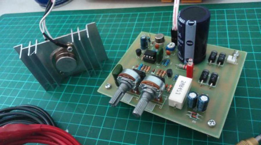
power unit - This is an indispensable attribute in the amateur radio workshop. I also decided to build myself an adjustable power supply, because I was tired of buying batteries every time or using random adapters. Here is its brief description: The power supply regulates the output voltage from 1.2 Volts to 28 Volts. And it provides a load of up to 3 A (depending on the transformer), which is most often enough to test the functionality of amateur radio designs. The circuit is simple, just right for a beginner radio amateur. Assembled on the basis of cheap components - LM317 And KT819G.LM317 regulated power supply circuit
List of circuit elements:
- Stabilizer LM317
- T1 - transistor KT819G
- Tr1 - power transformer
- F1 - fuse 0.5A 250V
- Br1 - diode bridge
- D1 - diode 1N5400
- LED1 - LED of any color
- C1 - electrolytic capacitor 3300 uF*43V
- C2 - ceramic capacitor 0.1 uF
- C3 - electrolytic capacitor 1 µF * 43V
- R1 - resistance 18K
- R2 - resistance 220 Ohm
- R3 - resistance 0.1 Ohm*2W
- P1 - construction resistance 4.7K
Pinout of the microcircuit and transistor

The case was taken from the computer's power supply. The front panel is made of PCB; it is advisable to install a voltmeter on this panel. I haven't installed it because I haven't found a suitable one yet. I also installed clamps for the output wires on the front panel.


I left the input socket to power the power supply itself. A printed circuit board made for surface-mounted mounting of a transistor and a stabilizer chip. They were secured to a common radiator through a rubber gasket. The radiator was solid (you can see it in the photo). It needs to be taken as large as possible - for good cooling. Still, 3 amperes is a lot!
