What is the size of inch pipes in mm? Pipe diameters in inches and millimeters Tapered and cylindrical threads
Read also
In Western technical literature, you will find all measurements in inch metrics. This state of affairs has historical roots. Great Britain was always ahead in terms of technical development, therefore, in all the colonies that it then owned (and there were many of them), this particular measurement system was used. Basically, technical specialists freely convert inches into sentiment and vice versa. To this day, in these countries, all measurements are made in inches as a standard. Next, we will talk about the main features and characteristics of inch threads and how it differs from metric threads.
Inch thread. Options
If we talk about ordinary measurement, then even in the mind it is not difficult to convert one value into another and vice versa. But as far as carving is concerned, you need to know simple, but important nuances. The fact is that there is great overlap between the metric and imperial metric for measuring lengths. The difference is the number of turns on the threaded pitch. In addition, this carving is distinguished by a different angle of inclination at its apex, which is 55°, if we refer to the Whitworth style. This is considered the norm in England, or, as they also say, the “British corner”. If we take the UNC and UNF standard, which is considered the standard in America, as a basis, then the angle here is 60°.
Metric standard and inch thread. The most fundamental differences
Types of inch threads:
- Outdoor;
- Conical;
- Cylindrical;
- Internal.
1 inch = 25.4 mm. This is the main difference. In documents this has a specific designation - 1´ (with a stroke).
If we talk about American standards, they have a division into threads with a large pitch, which they designate as UNC, and with a fine pitch, UNF. Also, for canonical inch threads the designation is NPT, and for pipe threads - NPSM.
What kind of thread is there and where is it used?
The types of threads used in production, construction and design, depending on the part, are divided into internal, external and conical.
- External is used for bolts, screws, pins and studs.
- Internal is used in the manufacture of plugs or nuts. It is cut into holes when you need to organize a connection in a certain place.
- To create a tight connection, as well as locking without additional parts, a conical inch thread is made.
Their designation follows the standard. d (D) is the outer diameter of the bolt or the inner diameter of the nut (d is the diameter of the bolt before threading). The internal diameter of the thread is designated d1 (D1). There is also a designation for the average diameter d2 (D2). This size depends on the nominal pitch, denoted by the letter P.
To indicate profile angle threads use the letter α. The indicator α = 55° will mean that the angle at the apex of the equilateral triangle of the thread tooth is 55°, and corresponds to the British Standard BSW inch thread. The UTS inch thread, widely used in Canada and the USA, has α = 60°.
Where are inch threads used?
α = 55° -inch thread used in industry for fixing mechanical components and parts using threaded connections. It is especially common in the process of repairing imported equipment and machines, as well as used cars. Metal products with inch threads are also produced in our country. During work, sometimes there is a need to convert metric threads to inch threads and vice versa. This can be done quickly and conveniently using a special reference book.
Threads according to the system of measures are divided into metric and inch. Metric and inch threads are used in threaded connections and screw drives. They are called threaded detachable connections, performed using threaded fasteners - bolts, screws, nuts, studs or threads directly applied to the parts being connected.
Metric thread (Fig. 1)
In profile it has the appearance of an equilateral triangle with an apex angle of 60°. The tops of the projections of the mating screw and nut are cut off. A metric thread is characterized by a screw diameter in millimeters and a thread pitch in millimeters. Metric threads are made with large and small pitches. A thread with a large pitch is taken as the main thread. Fine threads are used for adjustment and for screwing together thin-walled and dynamically loaded parts. Metric threads with large pitches are designated by the letter M and a number expressing the nominal diameter in millimeters, for example M20. For small metric threads, the pitch is additionally indicated, for example M20x1.5.
Rice. 1 Metric thread
Inch thread (Fig. 2)
An inch thread (Fig. 2) has the same profile as a metric thread, but its apex angle is 55° (Whitworth thread - British standard BSW (Ww) and BSF), its apex angle is 60° (American standard UNC and UNF). The outer diameter of the thread is measured in inches (1" = 25.4 mm) - dashes (") indicate inches. This thread is characterized by the number of threads per inch. American inch threads are made with coarse (UNC) and fine (UNF) pitch.
Rice. 2 Inch thread
Fastener size chart for American inch UNC machine threads with coarse pitch (60 degree profile angle)
| Size in inches | Size in mm | Thread pitch/inch |
| UNC No. 1 | 1.854 | 64 |
| UNC No. 2 | 2.184 | 56 |
| UNC No. 3 | 2.515 | 48 |
| UNC No. 4 | 2.845 | 40 |
| UNC No. 5 | 3.175 | 40 |
| UNC No. 6 | 3.505 | 32 |
| UNC No. 8 | 4.166 | 32 |
| UNC No. 10 | 4.826 | 24 |
| UNC No. 12 | 5.486 | 24 |
| UNC 1/4 | 6.35 | 20 |
| UNC 5/16 | 7.938 | 18 |
| UNC 3/8 | 9.525 | 16 |
| UNC 7/16 | 11.11 | 14 |
| UNC 1/2 | 12.7 | 13 |
| UNC 9/16 | 14.29 | 12 |
| UNC 5/8 | 15.88 | 11 |
| UNC 3/4 | 19.05 | 10 |
| UNC 7/8 | 22.23 | 9 |
| UNC 1" | 25.4 | 8 |
| UNC 1 1/8 | 28.58 | 7 |
| UNC 1 1/4 | 31.75 | 7 |
| UNC 1 1/2 | 34.93 | 6 |
| UNC 1 3/8 | 38.1 | 6 |
| UNC 1 3/4 | 44.45 | 5 |
| UNC 2" | 50.8 | 4 1/2 |
Thread
The thread can be internal or external.
- On bolts, studs, screws, pins and various others cylindrical parts cut external threads;
- Internal threads are cut in fittings, nuts, flanges, plugs, machine parts and metal structures.

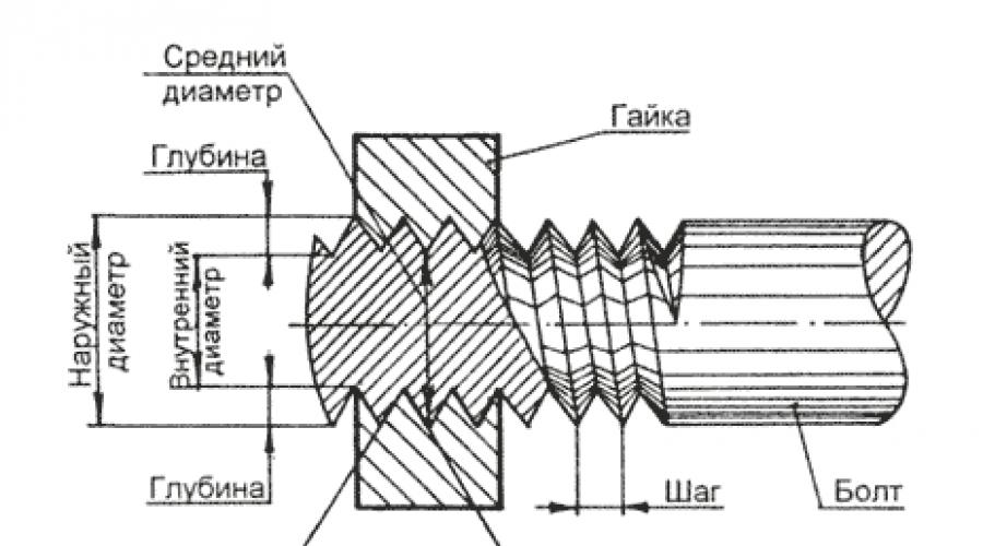
Rice. 3 Thread elements
The main thread elements are shown in Fig. 3 These include the following elements:
- thread pitch- the distance between the tops or bases of two adjacent turns;
- thread depth- the distance from the top of the thread to its base;
- thread angle- the angle between the sides of the profile in the plane of the axis;
- outside diameter - largest diameter bolt thread, measured along the top of the thread perpendicular to the axis of the thread;
- inner diameter- distance, equal to diameter cylinder on which a thread is screwed.
More about inch fasteners:
There are three thread systems used in mechanical engineering: metric, inch and pipe.
Metric thread(Fig. 145, a) has a triangular profile with an apex of 60°.


Rice. 145. Thread systems: a - metric, b - inch, c - pipe
There are six types of metric threads: main and minor -1; 2; 3; 4th and 5th. Small threads differ in pitch size for a given diameter, expressed in millimeters. Metric threads are designated by the letter M and numbers characterizing the dimensions of the outer diameter and pitch. For example, M42X4.5 denotes a metric main one with an outer diameter of 42 mm and a pitch of 4.5 mm.
Fine threads, in addition, have a number in the designation indicating the thread number, for example 2M20X1.75 - the second metric fine, outer diameter 20 mm, pitch 1.75 mm.
Inch thread(Fig. 145, b) has an angle of 55° at the apex. Inch threads are cut in the manufacture of spare parts for machines with inch threads and should not be cut on new products. Inch thread is characterized by the number of threads per inch (1") length. Outside diameter inch thread is measured in inches.
Pipe thread(Fig. 145, c) is measured in the same way as the inch one, in inches and is characterized by the number of threads per 1". The thread profile has an angle of 55°. pipe thread The diameter is conventionally taken to be the diameter of the hole of the pipe on the outer surface of which the thread is cut.
The tops of the protrusions of screws and nuts with pipe threads are made with flat or rounded cuts.
The flat-cut profile is easier to manufacture and is used for threads of conventional pipe connections. Pipe thread is designated: 1/4" PIPE; 1/2" PIPE. etc. (Table 25).
Table 25 Designation of threads in drawings
| Thread type | Legend | Notation elements | An example of a bolt and nut thread designation |
Metric basic |
M | Thread outer diameter (mm) or outer diameter and pitch (mm) | M64 or M64X6 or 64x6 |
Metric small |
1M | 1M 64X4 or 64X4 | |
| 2M | 2M 64X3 or 64X3 | ||
| 3m | 3M 64X2 or 64X2 | ||
| 4M | 4M 64X1.5 or 64X1.5 | ||
| 5M | 5M 64X1 or 64X1 | ||
Trapezoidal |
LADDER | Outer diameter and thread pitch (mm) | LADDER. 22x5 |
| UP | UP 70X10 | ||
Inch with a profile angle of 55° |
Nominal thread diameter in inches | 1" | |
Pipe cylindrical |
TUBE PR* PIPE. KR** | Symbol threads in inches | 3/4" TUBE OL 3/4" TUBE KR |
Pipe conical |
TUBE CONIC. | 3/4" TUBE |
* Profile with flat-cut tops (straight). ** The profile is rounded.
Threads can be right-handed or left-handed; by the number of passes - one-, two-, three-pass and multi-pass.
In order to determine the number of thread starts, it is enough to look at the end of the screw or nut and count how many thread ends there are on it.
As a rule, all fasteners (bolts, screws, screws, etc.) have single-start threads.
In our metric world, it can sometimes be difficult to navigate other measurement systems. We are sometimes surprised at how Americans or British can use outdated measures of length, mass, area, etc. And they, in turn, do not understand us - living according to the laws unified System Measurements. However, as with any rule, there are certain exceptions that are clear to everyone - residents of America, Foggy Albion, Europe, and Russia. This article is devoted to a review of pipe and metric threads, the variety of which one often encounters in everyday life.
Metric threads and their applications
Threaded connections are very common in construction, engineering, mechanical engineering, aerospace and Everyday life. Even children in kindergarten know what a screw and a nut are, since classes with a construction set cannot do without these parts. Despite the fact that the first screw was invented by Archimedes, and our ancient ancestors widely used helical gears in presses for squeezing oil from olive pits and sunflower seeds, as well as for raising water for irrigating fields, the idea of creating a real screw connection found its realization only in the 15th century, when one of the Swiss watchmakers was first able to turn the first screw using simple devices and nut.
At the same time, humanity did not quickly come to the reasonable idea that carvings should be the same in all countries of the world. Thus, widespread and familiar to everyone who has had at least a little experience with technology, metric thread appeared and was described in standards only after the introduction of a unified System of Measurements based on the standards of the meter, kilogram and second. So the appearance and widespread use of metric carving dates back to the end of the 19th century. Until that time, inch threads dominated the world.
The main difference between a metric thread and an inch thread is that all its parameters are tied to a millimeter, and the profile of the thread itself is based on an equilateral triangle, since all its angular dimensions are the same and equal to 60 degrees. In the standardization of metric threaded connections, it is important that the nut and bolt have the same not only angular dimensions of the thread, but also its diameter and pitch. Many people, especially those who own cars, have encountered an incomprehensible phenomenon when a screw and a nut have the same diameter, but it is impossible to screw the screw into the nut. This suggests that in this place a thread with a smaller pitch is used and in order for the screw to be screwed in without problems, its thread pitch must also be reduced.
The standards describing metric threads indicate that they must be designated by the letter M, and then the diameter of the thread and its pitch are indicated. The range of metric thread diameters ranges from one to six hundred millimeters. The thread pitch ranges from 0.075 to 3.5 mm. Fine pitch threads are used for measuring tool, threads with a medium pitch are for parts and assemblies loaded and operating under vibration conditions, and threads with a large pitch are used for fastening heavy load-bearing structures.
When creating standards for metric threads, various tolerances were taken into account, which determine the degree of roundness of the outer edge of the thread and deviation from the profile so that the screw and nut can be freely tightened until it stops by hand.
Although metric threads have not found widespread use in sealed joints, such a possibility is included in the standards. Thus, threads with the designation MK are used for self-sealing connections due to the taper of the outer and internal thread. Moreover, for a hermetic connection it is not necessary that the screw and nut have a conical thread. It is enough that this thread is cut on the screw.
Cylindrical metric threads are quite rare. Her designation is MJ. The main difference is in the screw, which has an increased root radius on the thread, which gives the threaded connection based on cylindrical metric threads higher heat-resistant and fatigue properties. This type of thread is used in the aerospace industry. However, a regular metric screw can be screwed into a nut with such a thread.
Despite the universal predominance of right-hand threads in all devices and mechanisms, it is still necessary to use left-hand threads to implement certain functions. Metric left-hand threads are no different from right-hand threads, except for the direction of rotation, which is opposite to right-hand screws. If a regular screw is twisted clockwise, then the left one is unscrewed in the same direction.
You can also sometimes encounter multi-start metric threads. It differs in that not one spiral, but two or even three are cut simultaneously onto the bolt and nut. Multi-start threads are often used in high-precision equipment, for example, in photographic equipment, in order to unambiguously position the position of parts during mutual rotation. Such a thread can be distinguished from a conventional thread by two or three starts of turns at the end.
Despite the very wide application metric threads, in many developed countries of the world traditionally the so-called inch threads remain in greater use. And pipe threads are universally measured in inches. And, despite the strong differences between these types of threads, plumbers all over the world do not need to explain the differences between a half-inch pipe and a three-quarter pipe.
Inch threads and their application
The difference between inch threads and metric threads is that the angle at the top of the thread is 55 degrees, the thread pitch is calculated as the ratio of the number of thread turns per inch of thread length. An inch is understood as a distance equal to 2.54 cm. Which originally corresponded to the length of the first phalanx thumb human hands, which is the same for almost all people.
Since the apex angle is different than in metric threads, it is not possible to combine metric and inch threads. In countries with the metric system, only inch pipe threads are used, which are designated by the letter G. The letter is followed by a fractional or whole denomination, which does not indicate the size of the thread, but the conditional clearance of the pipe in inches or fractions of an inch. A special feature of pipe threads is precisely the fact that it takes into account the thickness of the pipe walls, which can be thicker or thinner depending on the material of manufacture and the operating pressure for which the pipes are designed. Therefore, the inch standard for pipe threads is understood and accepted throughout the world as an exception to the metric rules.
In addition to simple cylindrical pipe threads, there are also conical pipe threads. It has the same characteristics as a regular pipe, with the exception of the taper, which allows you to create more sealed connections. Denoted by the letter R for external thread and Rc for internal. Left-hand threads are additionally marked with the letters LH, followed by a numerical value in whole and fractional fractions of an inch.
For use in connections other than plumbing, inch threads with an apex angle of 60 degrees are used in the USA and Canada. There is a fairly wide range of these threads, which differ in the range of thread pitch and other characteristics. It is worth noting that some threads from the inch series coincide with metric ones, which in some cases can be beneficial. For example, in photographic equipment, the diameter of the connecting thread by which the camera is attached to a tripod is the same all over the world, regardless of the country of origin, since the characteristics of this thread are the same for both metric and inch threads.
However, one should not confuse the English inch industrial thread, which was approved back in 1841, and was developed by Joseph Whitworth himself. This thread practically replicates the pipe thread, since it has an angle at the apex of 55 degrees. Screws and nuts with such threads are not compatible with inch fasteners from America and Canada.

In this article, I want not only to provide dry facts about the sizes of inch pipe threads with references to standards and GOSTs, but to bring to the reader an interesting fact about the features of the designation of the latter.
So, those who have already encountered pipe threads have been more than once surprised at the discrepancy between the outer diameter of the thread and its designation. For example, a 1/2-inch thread has an outer diameter of 20.95 mm, although logically with metric threads it should be 12.7 mm. The thing is that inch threads actually indicate the through hole of the pipe, and not the outer diameter of the thread. At the same time, by adding to the size of the hole in the pipe wall, we get the overestimated outer diameter that we are accustomed to in the designation of metric threads. Conventionally, the so-called pipe inch is 33.249 mm, that is, 25.4 + 3.92 + 3.92 (where 25.4 is the passage, 3.92 is the pipe wall). The pipe walls are taken based on the working pressure for the thread. Depending on the diameter, the pipes also increase accordingly, since a pipe with a larger diameter must have thicker walls than a pipe with a smaller diameter for the same operating pressure.
Pipe threads are divided into the following:
Cylindrical pipe thread
This is an inch thread based on BSW (British Standard Whitworth) thread and corresponds to BSP (British standard pipe thread) thread, has four pitch values 28,19,14,11 threads per inch. Cuts on pipes up to size 6", pipes over 6" are welded.
The profile angle at the apex is 55°, the theoretical profile height is Н=0.960491Р.
Standards:
GOST 6357-81 - Basic standards of interchangeability.
Cylindrical pipe thread. ISO R228, EN 10226, DIN 259, BS 2779, JIS B 0202.
Symbol: letter G, numerical value of the nominal diameter of the pipe in inches (inch), accuracy class of the average diameter (A, B), and letters LH for left-hand threads. For example, a thread with a nominal diameter of 1 1/4", accuracy class A is designated as G1 1/4-A. Once again, we would like to remind you that it should be borne in mind that the nominal thread size corresponds to the clearance of the pipe in inches. The outer diameter of the pipe is in some proportion with this size and more accordingly to the thickness of the pipe walls.
Designation of cylindrical pipe thread size (G), steps and nominal values of outer, middle and inner thread diameters, mm
| Thread size designation | Step P | Thread diameters | |||
|---|---|---|---|---|---|
| Row 1 | Row 2 | d=D | d 2 =D 2 | d 1 =D 1 | |
| 1/16" | 0,907 | 7,723 | 7,142 | 6,561 | |
| 1/8" | 9,728 | 9,147 | 8,566 | ||
| 1/4" | 1,337 | 13,157 | 12,301 | 11,445 | |
| 3/8" | 16,662 | 15,806 | 14,950 | ||
| 1/2" | 1,814 | 20,955 | 19,793 | 18,631 | |
| 5/8" | 22,911 | 21,749 | 20,587 | ||
| 3/4" | 26,441 | 25,279 | 24,117 | ||
| 7/8" | 30,201 | 29.0З9 | 27,877 | ||
| 1" | 2,309 | 33,249 | 31,770 | 30,291 | |
| 1⅛" | 37,897 | 36,418 | 34,939 | ||
| 1¼" | 41,910 | 40,431 | 38,952 | ||
| 1⅜" | 44,323 | 42,844 | 41,365 | ||
| 1½" | 47,803 | 46,324 | 44,845 | ||
| 1¾" | 53,746 | 52,267 | 50,788 | ||
| 2" | 59,614 | 58,135 | 56,656 | ||
| 2¼" | 65,710 | 64,231 | 62,762 | ||
| 2½" | 75,184 | 73,705 | 72,226 | ||
| 2¾" | 81,534 | 80,055 | 78,576 | ||
| 3" | 87,884 | 86,405 | 84,926 | ||
| 3¼" | 93,980 | 92,501 | 91,022 | ||
| 3½" | 100,330 | 98,851 | 97,372 | ||
| 3¾" | 106,680 | 105,201 | 103,722 | ||
| 4" | 113,030 | 111,551 | 110,072 | ||
| 4½" | 125,730 | 124,251 | 122,772 | ||
| 5" | 138,430 | 136,951 | 135,472 | ||
| 5½" | 151,130 | 148,651 | 148,172 | ||
| 6" | 163,830 | 162,351 | 160,872 | ||
Typically, the designation of pipe diameters uses values in inches, so we invite you to familiarize yourself with the table where the values in inches are converted to millimeters. In the scientific literature, the concept of “conditional passage” is used.
Under "conditional passage" understand a value (conventional diameter) that conventionally characterizes the internal diameter and does not necessarily coincide with the actual internal diameter. Conditional pass accepted from the standard range
1inch = 25.4 mm
Please note that if we take a 1" (one inch) pipe, then the outer diameter is not equal to 25.4 mm. This is where the confusion begins -"pipe inches". Let's try to clarify this issue. If you look at the parameters of a cylindrical pipe thread, you will notice that the outer diameter (at one inch) is 33.249 mm, not 25.4.
The nominal diameter of the thread is conventionally related to the internal diameter of the pipe, and the thread is cut on the outer diameter. So we get a diameter of 25.4 mm + two pipe wall thicknesses ≈ 33.249 mm. Thus appeared"pipe inch".
| Diameters in inches | Accepted nominal pipe diameters, mm | External dimensions of steel pipe according to GOST 3262-75, mm |
| ½ " | 15 | 21,3 |
| ¾ " | 20 | 26,8 |
| 1 " | 25 | 33,5 |
| 1 ¼ " | 32 | 42,3 |
| 1 ½ " | 40 | 48 |
| 2 " | 50 | 60 |
| 2 ½" | 65 | 75,5 |
| 3 "" | 80 | 88,5 |
| 4 " | 100 | 114 |
The KIT company in Domodedovo provides turnkey installation of water treatment systems and maintenance of water treatment systems.
We also offer you an innovative professional cleaning product sewer pipes and eliminating odors with Likvazim.
With the KIT company it is reliable and convenient!
This article will discuss concepts related to threaded connections such as metric and inch threads. To understand the intricacies associated with a threaded connection, it is necessary to consider the following concepts:
Tapered and cylindrical threads
The rod itself with tapered thread is a cone. Moreover, according to international rules, the taper should be 1 to 16, that is, for every 16 units of measurement (millimeters or inches) with increasing distance from the starting point, the diameter increases by 1 corresponding unit of measurement. It turns out that the axis around which the thread is applied and the conditional straight line drawn from the beginning of the thread to its end along the shortest path are not parallel, but are located at a certain angle to each other. To explain even more simply, if we had a length threaded connection was 16 centimeters, and the diameter of the rod at its starting point would be 4 centimeters, then at the point where the thread ends, its diameter would already be 5 centimeters.
Rod with cylindrical thread is a cylinder, therefore there is no taper.
Thread pitch (metric and inch)
 The thread pitch can be large (or main) and small. Under thread pitch refers to the distance between the threads from the top of the thread to the top of the next thread. You can even measure it using a caliper (although there are also special meters). This is done as follows - the distance between several tops of the turns is measured, and then the resulting number is divided by their number. You can check the measurement accuracy using the table for the corresponding step.
| Cylindrical pipe thread according to GOST 6357-52 | |||||
|---|---|---|---|---|---|
| Designation | Number of threads N by 1" |
Thread pitch S, mm |
Outside diameter thread, mm |
Average diameter thread, mm |
Inner diameter thread, mm |
| G1/8" | 28 | 0,907 | 9,729 | 9,148 | 8,567 |
| G1/4" | 19 | 1,337 | 13,158 | 12,302 | 11,446 |
| G3/8" | 19 | 1,337 | 16,663 | 15,807 | 14,951 |
| G1/2" | 14 | 1,814 | 20,956 | 19,754 | 18,632 |
| G3/4" | 14 | 1,814 | 26,442 | 25,281 | 24,119 |
| G7/8" | 14 | 1,814 | 30,202 | 29,040 | 27,878 |
| G1" | 11 | 2,309 | 33,250 | 31,771 | 30,292 |
Nominal thread diameter
The labeling usually contains nominal diameter, which in most cases is taken to be the outer diameter of the thread. If the thread is metric, then you can use a regular caliper with scales in millimeters to measure. Also, the diameter, as well as the thread pitch, can be viewed using special tables.
Metric and inch threads with examples
 Metric thread– has the designation of the main parameters in millimeters. For example, consider an elbow fitting with an external cylindrical thread. EPL 6-GM5. IN in this case EPL says that the fitting is angled, 6 is 6 mm - the outer diameter of the tube connected to the fitting. The letter “G” in its marking indicates that the thread is cylindrical. “M” indicates that the thread is metric, and the number “5” indicates the nominal diameter of the thread, equal to 5 millimeters. Fittings (from those we have on sale) with the letter “G” are also equipped with a rubber o-ring, and therefore do not require fum tape. The thread pitch in this case is 0.8 millimeters.
Main settings inch thread, according to the name, are indicated in inches. This can be a 1/8, 1/4, 3/8 and 1/2 inch thread, etc. For example, let's take a fitting EPKB 8-02. EPKB is a type of fitting (in this case a splitter). The thread is conical, although there is no reference to this using the letter “R”, which would be more correct. 8 - indicates that the outer diameter of the connected tube is 8 millimeters. A 02 - that the connecting thread on the fitting is 1/4 inch. According to the table, the thread pitch is 1.337 mm. The nominal thread diameter is 13.157 mm.
The profiles of the conical and cylindrical threads coincide, which allows fittings with conical and cylindrical threads to be screwed together.
| inches | mm. | inches | mm. | inches | mm. | inches | mm. | inches | mm. |
|---|---|---|---|---|---|---|---|---|---|
| - | - | 1 | 25,4 | 2 | 50,8 | 3 | 76,2 | 4 | 101,6 |
| 1/8 | 3,2 | 1 1/8 | 28,6 | 2 1/8 | 54,0 | 3 1/8 | 79,4 | 4 1/8 | 104,8 |
| 1/4 | 6,4 | 1 1/4 | 31,8 | 2 1/4 | 57,2 | 3 1/4 | 82,6 | 4 1/4 | 108,8 |
| 3/8 | 9,5 | 1 3/8 | 34,9 | 2 3/8 | 60,3 | 3 3/8 | 85,7 | 4 3/8 | 111,1 |
| 1/2 | 12,7 | 1 1/2 | 38,1 | 2 1/2 | 63,5 | 3 1/2 | 88,9 | 4 1/2 | 114,3 |
| 5/8 | 15,9 | 1 5/8 | 41,3 | 2 5/8 | 66,7 | 3 5/8 | 92,1 | 4 5/8 | 117,5 |
| 3/4 | 19,0 | 1 3/4 | 44,4 | 2 3/4 | 69,8 | 3 3/4 | 95,2 | 4 3/4 | 120,6 |
| 7/8 | 22,2 | 1 7/8 | 47,6 | 2 7/8 | 73,0 | 3 7/8 | 98,4 | 4 7/8 | 123,8 |
Inch thread parameters
|
Outer diameter of the connected pipe |
SAE Thread Rating |
UNF thread rating |
Outer thread diameter, mm |
Average thread diameter, mm |
Thread pitch |
||
|
mm |
inch |
mm |
threads/inch |
||||
| 6 | 1/4"""" | 1/4"""" | 7/16""""-20 | 11,079 | 9,738 | 1,27 | 20 |
| 8 | 5/16"""" | 5/16"""" | 5/8""""-18 | 15,839 | 14,348 | 1,411 | 18 |
| 10 | 3/8"""" | 3/8"""" | 5/8""""-18 | 15,839 | 14,348 | 1,411 | 18 |
| 12 | 1/2"""" | 1/2"""" | 3/4""""-16 | 19,012 | 17,33 | 1,588 | 16 |
| 16 | 5/8"""" | 5/8"""" | 7/8""""-14 | 22,184 | 20,262 | 1,814 | 14 |
| 18 | 3/4"""" | 3/4"""" | 1""""-14 | 25,357 | 23,437 | 1,814 | 14 |
| 18 | 3/4"""" | --- | 1""""1/16-14 | 26,947 | 25,024 | 1,814 | 14 |
| 20 | 7/8"""" | --- | 1""""1/8-12 | 28,529 | 26,284 | 2,117 | 12 |
| 22 | 7/8"""" | 7/8"""" | 1""""1/4-12 | 31,704 | 29,459 | 2,117 | 12 |
| 22 | 7/8"""" | --- | 1""""3/8-12 | 34,877 | 32,634 | 2,117 | 12 |
| 25 | 1"""" | 1"""" | 1""""1/2-12 | 38,052 | 35,809 | 2,117 | 12 |
Copper conductors, wires and cables
| Conductor cross-section, mm | Copper conductors, wires and cables | |||
| Voltage, 220 V | Voltage, 380 V | |||
| current, A | power, kWt | current, A | power, kWt | |
| 1,5 | 19 | 4,1 | 16 | 10,5 |
| 2,5 | 27 | 5,9 | 25 | 16,5 |
| 4 | 38 | 8,3 | 30 | 19,8 |
| 6 | 46 | 10,1 | 40 | 26,4 |
| 10 | 70 | 15,4 | 50 | 33,0 |
| 16 | 85 | 18,7 | 75 | 49,5 |
| 25 | 115 | 25,3 | 90 | 59,4 |
| 35 | 135 | 29,7 | 115 | 75,9 |
| 50 | 175 | 38,5 | 145 | 95,7 |
| 70 | 215 | 47,3 | 180 | 118,8 |
| 95 | 260 | 57,2 | 220 | 145,2 |
| 120 | 300 | 66,0 | 260 | 171,6 |
Aluminum conductors, wires and cables
| Cross-section of current-carrying conductor, mm | Aluminum conductors, wires and cables | |||
| Voltage, 220 V | Voltage, 380 V | |||
| current, A | power, kWt | current, A | power, kWt | |
| 1,5 | 19 | 4,1 | 16 | 10,5 |
| 2,5 | 27 | 5,9 | 25 | 16,5 |
| 4 | 38 | 8,3 | 30 | 19,8 |
| 6 | 46 | 10,1 | 40 | 26,4 |
| 10 | 70 | 15,4 | 50 | 33,0 |
| 16 | 85 | 18,7 | 75 | 49,5 |
| 25 | 115 | 25,3 | 90 | 59,4 |
| 35 | 135 | 29,7 | 115 | 75,9 |
| 50 | 175 | 38,5 | 145 | 95,7 |
| 70 | 215 | 47,3 | 180 | 118,8 |
| 95 | 260 | 57,2 | 220 | 145,2 |
| 120 | 300 | 66,0 | 260 | 171,6 |
Inch thread sizes
| Thread diameter in mm | Thread pitch in mm | Number of threads per 1" | |||
| outer d | average d | internal d | |||
| 3/16 | 4,762 | 4,085 | 3,408 | 1,058 | 24 |
| 1/4 | 6,350 | 5,537 | 4,724 | 1,270 | 20 |
| 5/16 | 7,938 | 7,034 | 6,131 | 1,411 | 18 |
| 3/8 | 9,525 | 8,509 | 7,492 | 1,588 | 16 |
| 1/2 | 12,700 | 11,345 | 9,989 | 2,117 | 12 |
| 5,8 | 15,875 | 14,397 | 12,918 | 2,309 | 11 |
| 3/4 | 19,05 | 17,424 | 15,798 | 2,540 | 10 |
| 7/8 | 22,225 | 20,418 | 18,611 | 2,822 | 9 |
| 1 | 25,400 | 23,367 | 21,334 | 3,175 | 8 |
| 1 1/8 | 28,575 | 26,252 | 23,929 | 3,629 | 7 |
| 1 1/4 | 31,750 | 29,427 | 27,104 | 3,629 | 7 |
| 1 1/2 | 38,100 | 35,39 | 32,679 | 4,233 | 6 |
| 1 3/4 | 44,450 | 41,198 | 37,945 | 5,080 | 5 |
| 2 | 50,800 | 47,186 | 43,572 | 5,644 | 4 1/2 |
| Nominal thread diameter in inches | |||||
| Thread diameter in mm | Thread pitch in mm | Number of threads per 1" | |||
| outer d | average d | internal d | |||
| 1/8 | 9,729 | 9,148 | 8,567 | 0,907 | 28 |
| 1/4 | 13,158 | 12,302 | 11,446 | 1,337 | 19 |
| 3/8 | 16,663 | 15,807 | 14,951 | 1,337 | 19 |
| 1/2 | 20,956 | 19,794 | 18,632 | 1,814 | 14 |
| 5/8 | 22,912 | 21,750 | 20,588 | 1,814 | 14 |
| 3/4 | 26,442 | 25,281 | 24,119 | 1,814 | 14 |
| 7/8 | 30,202 | 29,040 | 27,878 | 1,814 | 14 |
| 1 | 33,250 | 31,771 | 30.293 | 2,309 | 11 |
| 1 1/8 | 37,898 | 36,420 | 34,941 | 2,309 | 11 |
| 1 1/4 | 41,912 | 40,433 | 38,954 | 2,309 | 11 |
| 1 3/8 | 44,325 | 32,846 | 41,367 | 2,309 | 11 |
| 1 1/2 | 47,805 | 46,326 | 44,847 | 2,309 | 11 |
| 1 3/4 | 53,748 | 52,270 | 50,791 | 2,309 | 11 |
| 2 | 59,616 | 58,137 | 56,659 | 2,309 | 11 |
Unit conversion table
| Conversion of energy units | Conversion of pressure units |
|---|---|
| 1 J = 0.24 cal | 1 Pa = 1 N/m*m |
| 1 kJ = 0.28 Wh | 1 Pa = 0.102 kgf/m*m |
| 1 W = 1 J/s | 1 atm =0.101 mPa =1.013 bar |
| 1 cal = 4.2 J | 1 bar = 100 kPa = 0.987 atm |
| 1 kcal/h = 1.163 W | 1 PSI = 0.06895 bar = 0.06805 atm |
Size conversion tables: simple and fast
The process of selecting the required cross-sectional sizes of threads, cables and pipes often takes a lot of time. In addition to the fact that it is necessary to select the appropriate dimensions, taking into account the parameters of the equipment, the customer has to independently convert the data into suitable units of measurement. This process requires significant time.
We simplify this task, since we suggest you use ready-made translation tables. On the page of our website you will find tables that will help you easily select the necessary threads inch pipes, copper and aluminum conductors of wires and cables. Also, you can use the translation table inch sizes in metric, thereby accurately calculating required dimensions sections.
Unfortunately, most equipment manufacturers leave the customer alone with the calculations. Therefore, a person has to independently search the Internet for translation tables in order to select optimal sizes wire sections and pipe diameters.
We value the time of our clients, providing everyone with the opportunity to use ready-made solutions. Translated in our tables standard sizes from inches to millimeters.
On this page you will also find translations of basic energy units and pressure units, therefore, you will be able to choose the right refrigeration equipment, considering individual conditions placement and operating modes of units.
On construction market 2 sizes of designs are popular:
- 1\2 and 3\4 - form a separate category. due to special thread parameters (1.814), per 1 unit. measures account for 14 threads;
- within 1 - 6 inches, the pitch is reduced to 2.309, forming 11 threads, which does not affect the reduction or improvement of the quality of the connection.
One inch is 25.4 mm long, it is used to determine the internal parameters, but when laying reinforced pipes, the diameter is 33.249 mm (including the internal section and 2 walls). In assortment steel structures there is an exception - ½ inch products, where the outer section is 21.25 mm. This parameter is used when calculating the dimensions of pipes with cylindrical threads. When making calculations for pipes with a cross section of 5 inches, the internal dimension will be 12.7 cm, and the external dimension will be 166.245 (reduction to 1 decimal place is allowed).

Difference between measurement systems
In terms of external parameters, inch designs do not differ from metric ones; the difference lies in the type of notches. There are 2 types of threads according to the inch system - English and American. The first option corresponds to a notch angle of 55 degrees, and the metric (American) system with an angle of 60 degrees. generally accepted.
At different degrees, it is difficult to distinguish between an angle of 55 for inch and 60 for metric designs, and the rounding of the threads is immediately visible, making it impossible for an error to occur. To measure the thread pitch, a thread gauge is used, but instead of it, a regular ruler or other device can be used well.

Replacing steel pipes with polymer ones
In gas and water supply network steel products are used, the diameter of which is indicated in inches (1", 2") or fractions (1/2", 3/4"). When measuring the cross-section of a 1" pipe, the result will be 33.5 mm, which corresponds to 1" (25.4 mm). When arranging pipeline reinforcing elements, where the parameters are indicated in inches, no difficulties arise. But when installing products made of PP, copper or stainless steel instead of steel structures, it is necessary to take into account the difference in name and parameters.

To create a given flow level, the internal diameter of the pipes is taken into account. For ordinary inch pipes it is 27.1 mm, for reinforced pipes it is 25.5 mm, closest to 1". Pipelines are designated in conventional units of flow area Du (DN). It determines the parameters of the lumen of pipes and is indicated in digital values. The pitch of the conventional flow area sections are selected taking into account an increase in throughput characteristics by 40-60% with an increase in the index. If the external one is known. cross section and the purpose of the structures, using the size table, the internal cross-section is determined.

During connection steel pipes with polymer structures, replacing one with another, conventional adapters are used. Dimensional discrepancies result from the use of copper, aluminum or stainless steel products manufactured to metric standards. The actual metric dimensions of the pipes are taken into account - internal and external.

Steel pipes of the Russian Federation in comparison with the European standard
To compare the range of pipes according to GOST of the Russian Federation and European standards, the following table is used:

How to decide on the diameter?
From diameter water pipes their throughput characteristics depend - the volume of water passed per 1 unit. time. It depends on the speed of water flow. As it increases, the risk of pressure drop in the line increases. Flow characteristics are calculated using formulas, but when planning intra-apartment wiring, they take pipes of certain parameters.
For the plumbing system:
- 1.5 cm (1/2 inch)
- 1 cm (3/8 inch).
For the riser, structures with an internal cross section are used:
- 2.5 cm (1 inch);
- 2 cm (3/4 inch).

Considering that the internal cross-section of half-inch polymer pipes varies in the range from 11 to 13 mm, and one-inch ones - from 21 to 23, will be able to determine the exact parameters when replacing experienced plumber. At complex type wiring, numerous joints, turns and network laying on long distance, reducing pressure, it is necessary to provide for the possibility of routing pipes with a large cross-section. As the diameter increases, the pressure level increases.
Below is a table for determining the permeability of steel pipes:

Steel pipe diameter
The cross-section of the pipes corresponds to a number of indicators:
- Nominal diameter (DN, Dy) – nominal parameters (in mm) of the internal cross-section of pipes or their rounded values, in inches.
- Nominal parameter(Dn Dn,).
- External size.
The metric calculation system allows you to classify structures into small - from 5...102 mm, medium - from 102...426, large - 426 mm and more.
- Wall thickness.
- Inner diameter.
The internal cross-section of pipes with different threads corresponds to the following parameters:
- 1/2 inch pipeline - 1.27 cm;
- 3/4 inch - 1.9 cm;
- 7/8 inches - 2.22 cm;
- 1 inch – 2.54 cm;
- 1.5 inches - 3.81 cm;
- 2 inches - 5.08 cm.
To determine the thread diameter, the following indicators are used:
- 1/2 inch pipeline – 2.04 - 2.07 cm;
- 3/4 inches – 2.59 - 2.62 cm;
- 7/8 inches – 2.99 - 3 cm;
- 1 inch – 3.27 - 3.3 cm;
- 1.5 inches - 4.58 - 4.62 cm;
- 2 inches – 5.79 - 5.83 cm.

Table of correspondence between the diameter of steel pipes and polymer structures:

Steel pipe prices:

PP pipe diameter
PP pipes are produced with a diameter from 0.5 to 40 cm or more. The diameter is internal and external. The first indicator allows you to find out the volume of media passed through in 1 unit. time. The external cross-section is used to carry out construction calculations, namely the selection of a niche or hole for laying a highway. External parameters allow you to choose the right fittings with the corresponding internal indicators.

- Small – 0.5; 1; 1.5; 2; 2.5; 3.2; 4; 5; 6.3 and 7.5 cm are used for heating systems, drainage and water supply in private buildings. An internal cross-section of 3.2 cm is most popular in multi-story buildings.
- Average – 8; 9; 10; eleven; 12.5; 16; 20; 25 and 31.5 cm are used for arranging water supply and sewer systems, allowing you to change cast iron products with similar external parameters. Inner size in 8, 9 and 10 cm ideal for chemical media.
- Large - 40 cm or more is used for arranging cold water supply and ventilation systems.
Pipes are marked in inches and mm. When choosing designs for plumbing and heating system, the wall thickness is taken into account, affecting the conditional passability of highways with the same external parameters. With an increase in its parameter, an increase in pressure is allowed in plumbing system. Small dimensions allow you to reduce the cost of purchasing material and water consumption.


Cost of PP pipes:

Video