Which electric motor is suitable for a woodworking machine. Simple universal woodworking machine. A simplified version of the manufacture of a woodworking machine
Read also
The woodworking machine is used not only in carpentry or industrial workshops. Using this device on the farm, it is possible to independently manufacture any piece of furniture and even build a house. We will consider how to make woodworking machines with our own hands further.
Woodworking machine device
Each woodworking machine consists of basic and additional parts. The main parts are:
- work plate,
- bed,
- shaft device,
- one of the cutting tools
- the mechanism responsible for the transmission of motion.

Additional elements of the woodworking machine:
- areas with a fence of a dangerous place,
- point responsible for the supply of wood material,
- machine starter,
- lubrication device.
A heavy-weight structure made of cast iron or solid steel alloy is used as a bed. All structural parts of the machine are installed on the bed. She is responsible for their location and for the stability of the device. In most cases, the bed is installed on a reinforced concrete foundation.
The main function of the desktop is to fix all work items. It is made from pre-polished cast iron. There are two versions of the table: movable and fixed.
To attach the cutting tool to the machine, a working shaft device is used. There are several varieties of this device, which differ in the type of cutting tool attached to it. Allocate:
- saw,
- knife,
- spindle operating shaft.
It is always made of turned steel, characterized by strength, balance and the presence of a place on which the cutting tool is attached.

Various parts act as a cutting tool. They differ in design and functional features, as well as in shape and size.
They are made from high quality carbon steel. Consider some types of cutting tools for a woodworking machine:
- a device in the form of a round disk is used on circular saw machines;
- a tool in the form of a saw band is used on band saws;
- flat and shaped knives are used on milling, planing or tenoning structures;
- drills are used on drilling woodworking machines;
- the slotting chain is used on chain slotting devices;
- for milling and tenoning machines, an excellent option would be to use hooks, slotted discs and cutters;
- on woodworking machines of the scraper type, scraper knives are used;
- for grinding machines, a rolled skin is used.
Woodworking machines photo:

Advantages and scope of use of woodworking machines
Woodworking machines have a large number of advantages over hand tools for processing wood surfaces. Firstly, the speed of the woodworking machine is much higher, so using this machine significantly saves time for processing one part.
The versatile woodworking machine is capable of processing a variety of parts, and performs several types of work, such as grinding, milling and drilling.
Subject to all the manufacturing technologies of a woodworking machine, such a device can serve its owner for decades.
Modern CNC woodworking machines have improved work functions, during which the person working on the machine is practically not overworked. It is enough to launch a pre-recorded program and install the part. At this rate, the number of parts is increasing, and the time to process them is decreasing. Such machines are able to work around the clock and continuously.
If we consider woodworking machines for domestic purposes, then among them there are also many advantages:
1. These machines are equipped with a motor with an average power of 2.2 kW, such power allows you to work quickly and without overloading.

2. Such machines have good quality of processed products.
3. They do not require high maintenance and operation costs.
4. The ability to install additional attachments allows you to increase the number of functions of a household woodworking machine.
5. The main functions of this machine are sawing, grinding, milling and drilling wood.
6. A large number of functions and versatility of such equipment allows you to work with various types of wood, while performing a variety of operations.
7. If we consider reviews about woodworking machines, then for private or home use, buying or self-manufacturing a household machine would be an excellent option.
The scope of use of woodworking machines is quite wide, because of their versatility. They are used in both private and industrial woodworking.
With the help of woodworking machines, semi-finished elements or blanks are made, such as boards, bars, veneer, shavings. They are also used to make parts for wooden products or entire wooden structures, for example: parquet, licks, furniture, parts of musical instruments, etc.
All tasks that are associated with wood processing are easily solved by a woodworking machine. This device carries out not only sawing and drilling wood, but also its grinding and even carving, the manufacture of which manually takes tens of times more time.

The main types of woodworking machines
In relation to the technological principle of wood processing, woodworking machines are divided into:
- universal,
- specialized,
- narrow production.
General purpose machines are widely popular due to their versatility. They are used in a variety of industrial and individual enterprises. The peculiarity of such a machine is that it is possible to perform almost all types of wood processing on it. But at the same time, the quality of the work performed will be slightly lower than, for example, that of a specialized machine.
Specialized woodworking machines are capable of performing only one function, while being able to reconfigure and are used in different industries.
The use of special machines is reduced to the manufacture of certain parts, other operations on such a machine cannot be performed.
Specialized machines are:
- milling type,
- circular type,
- band saw type,
- longitudinal milling type,
- drilling type,
- tenon type,
- drilling and milling type,
- turning type,
- slotted type,
- grinding type.

One of the main types of wood processing are milling machines that perform the following functions:
- milling parts in different directions,
- shaped production of details,
- clippings of extraordinary elements,
- groove making.
Milling woodworking machines are divided into:
- devices of a simple type, which are single- and double-spindle;
- copying machines - are engaged in the manufacture of small parts, based on the use of complex technologies;
- carousel machines perform processing of flat and figured type.
There are also desktop-type woodworking machines, which in turn are divided into:
- vertical type machines
- horizontal type,
- longitudinal type,
- highly specialized type.
Lathes - work with different types of wood from soft to hard woods. They are equipped with a copier that produces the same type of parts. The scope of use is not limited to art workshops. Lathes produce parts of various shapes: conical, cylindrical.

Lathes are divided into:
- center - a tool is fed into them mechanically or manually, which can be cut, designed for the manufacture of parts of the same type;
- face-turning - make model parts;
- round stick - produce products in which the diameter changes along the length of the part.
Woodworking machines of the circular saw type perform longitudinal, angular and transverse sawing. There are manual and mechanized.
Reamus machines plan boards under a flat slope. There are:
- unilateral,
- bilateral,
- multi-knife.
To determine the type or type of woodworking machine, there are special designations. The first one or two letters indicate the type according to the principle of operation, and the next - the technological properties of the machine. To find out the number of work items on the node, there are numbers between these letters.
In relation to the accuracy of the processing of the part, woodworking machines are distinguished:
- first class (O) - denoting a very high accuracy of processing;
- second class (P) - accuracy is eleven or twelve qualifications;
- third class (C) - with an accuracy of thirteen fifteen qualifications;
- fourth class (H) - with reduced accuracy.

Homemade woodworking machines - manufacturing instructions
To make a universal woodworking machine, you will need:
- electric motor,
- shaft,
- drill chuck,
- bed, which is adjustable in height.
This tool sharpens, grinds and cuts wooden parts with ease.
When choosing an engine, pay attention to the following parameters:
- synchronicity,
- power in the range from 0.6 to 1.5 kW,
- the average speed of rotation of the shaft per minute is 2500 revolutions.
The shaft must have a fixture for attaching a drill chuck. If it is missing, you need to sharpen the end of the shaft with a file. The diameter of the mount should be slightly larger than the diameter of the cartridge. Then turn on the engine and sharpen the chuck so that it is fixed on the shaft. Using a needle file and lapping paste, adjust the chuck to fit the shaft. In the absence of such a paste, you should rub the sandpaper and dilute its abrasive with oil.
In the central part of the shaft, a hole should be drilled and threaded M5 M6, in order to protect against accidental slipping of the cartridge, it should be fixed with a countersunk head.
The standard arrangement of the machine allows you to place a wooden part in different positions in relation to the machine.

Woodworking machine drawings:
The table is fastened to the frame with two bolts, and the slats are fastened with fixing brackets.
For the construction of the frame, you will need six metal corners, the cross section of which is 2.5x2.5 cm, and one corner with a cross section of 4x4 cm. Their length is 30 cm. Use a welding machine to connect. Monitor the quality of the welds, as the machine constantly vibrates during operation.
For the manufacture of countertops, it is possible to use plastic, metal, board or plywood.
To install the parts on the table space, you will need to make a bar and bracket. In order to install a pulley, milling cutter or saw in the chuck hole, additional transition bushings and mandrels should be made.
A simplified version of the manufacture of a woodworking machine
The manufacture of a woodworking machine must begin with its functional purpose, the fewer functions the device performs, the easier it is to build.
To make a bed, take a metal corner or pipe. Weld a strong frame, and then strengthen it with additional corners to reduce the vibration level of the structure.
It is better to install the bed in a certain place and concrete it into the floor.
The next stage is the construction or purchase of a woodworking shaft, which has a width of 30 cm, which can accommodate several knives at once.
For the construction of the table, use strong and even steel, about 1 cm thick. To adjust the thickness of the planing, make a folding table consisting of two separate parts. So the height of one piece will be adjustable. In this case, the second part requires rigid fixation.
As an engine, take a device with a power of 2 to 5 kW, with a rotation speed of 2000 to 3000 rpm. If the speed is lower, it will affect the quality of the machine.
Mount the engine on the frame. Tighten the straps and make a moving corner that will help you adjust the sawing length of the part. Install another corner that will align the position of the workpiece with respect to the cutting tool.
The site of the woodworking machine, submitted to the readers of the site, I independently designed, made with my own hands and now I successfully use it when building a house on my site. I am convinced how successful the design turned out: compact, technological, quite, I think, suitable for its “replication”. The machine is so simple that super-detailing for its manufacture is unlikely to be required. There is free access to all attachment points. So, if desired, the structure can be easily disassembled and, transported in the trunk of a car, assembled in a new place in about thirty minutes.
Drawings of a woodworking machine


The proposed version of the universal woodworking machine - with load-bearing elements made of steel angle and sheet steel. Although I know: it will not be difficult for an experienced do-it-yourselfer to find a suitable replacement for these materials from what is at hand. Of course, with the maximum use of technical solutions that ensure compactness, manufacturability of assembly and disassembly.
Take at least welded assemblies and parts. There are few of them. First of all, this is a support-base made of a steel corner 50x50 mm. Then there is a frame for installing the L-shaped racks of the table and bearing assemblies of the driven shaft with the working bodies of the machine. It is made of a steel corner 60x60 mm. Welding work will also be required when the bushings of the L-shaped racks are rigidly fixed to the table top, the ruler-limiter and a special turntable for the electric motor are made.
The latter deserves special mention. It is welded from pieces of a steel angle 40x40 mm and a bar, at the ends of which an M12 internal thread is cut. The bar serves as the pivot axis of the platform, is inserted between the uprights and fixed on both sides with M12 bolts. The asynchronous three-phase motor AIR100B4UZ with a 100 mm two-strand pulley is mounted on the platform using four bolts with nuts and Grover washers.
The tension in the V-belt transmission is carried out by twisting the lamb on the rod passing through the hole in the platform, followed by locking.
Support-base, frame and four posts made of steel angle 40x40mm, fastened together with M20 bolts, form a frame. Chute for sawdust and shavings made of sheet aluminum, other components and parts, including equipment for starting and controlling the electric motor, are screwed to it.
The table top consists of two identical 6 mm steel plates fastened together by spars using M12 countersunk screws and locknuts. As already noted, four bushings are welded to the lower surface of the cover, in which the L-shaped racks can be rotated. As for the limiter ruler, it is attached to the rails using compound clamps and M8 screws.
A few words about the engine. Since the machine uses a three-phase AIR100B4UZ (3 kW, 1410 rpm), it was necessary to introduce phase-shifting start and work capacitors to include it in a single-phase network. And for the most efficient use, provide for the connection of the windings either with a “star” or a “triangle”. The first of these modes (with the symbol "U") is recommended for sawing and planing with reduced load (when the boards are not too thick). The "Start" button is pressed here if BA1 is disabled, BA2 is enabled, and BAZ is in the "U" position. In this case, the magnetic starter will work and, by blocking BV1, will ensure a reliable supply of voltage to the motor windings.
The mode with the symbol "D" is work with increased power. They switch to it after the electric motor, having thoroughly accelerated, picks up the required speed in the “U” mode. Then boldly increase the capacitance of the phase-shifting capacitor by additionally connecting another 100 microfarads using BA1. And only then, preventing strong starting currents, they switch the windings to the “triangle”, moving the BAZ to the “D” position.
It is easy to stop the engine in any of the modes. To do this, just click on the "Stop" button. Then the supply voltage to the coil winding of the magnetic starter will immediately stop, and it will de-energize the electric motor.
As for the BA4 "Reverse" switch, as practice has shown, it can not be installed. And the required direction of rotation is achieved in this case during commissioning by "reversing the ends" of one of the windings.
And one more remark regarding the features of the functioning of the scheme under consideration. After stopping the motor, both capacitors must be discharged. To do this, you just need to ... turn on BA1 and BA2.
It is time to consider the features of the operation of the machine itself as a whole. It is better to do this by referring to the illustrations.
First of all, the adjustment of the height of the cut, as well as the thickness of the chip removal. The required results are achieved here ... by turning the nuts. Special, adjusting, with subsequent fixation with a lower nut.
Changing the tilt of the table (when sawing at an angle other than a straight one) is carried out by simply raising (or lowering) the posts (on the opposite side of the saw blade) to the required height. Optimum shaft speeds (1500 rpm for sawing and approximately 3500 rpm for planing the starting material) are achieved by appropriate selection of the diameters of the driving and driven pulleys.
Other possibilities of the machine? They are directly dependent on which tool is on the working shaft. For example, using various cutters, you can successfully select grooves, quarters. Replacing the saw blade with a cutting wheel, we get a reliable mechanical metal cutter. And with the installation of emery machine for sharpening tools.
But all this requires accuracy. And, of course, the strictest, strict observance of safety regulations. In particular, when installing the shaft on the bed frame, it must be fixed rigidly, without distortion. Having tightened the bolts first on one support, make sure that the other has not risen above the frame and is not excessively pressed against it. Then you need to approach the tightening of the bolts on the second support with the same precaution. Correct the skew immediately by placing metal gaskets under the supports. Bearings must be filled with refractory grease. Make sure that sawdust and shavings do not get into them in any case.
No less care should be taken with the planer. The knives of this working body must be securely fastened with bolts. It is worth recalling that when the planer is not in use, it must be closed with a special metal cover (not shown in the figure).
In order to avoid any surprises, the nuts for fastening the “circular” must certainly be with Grover's washers, and it will not hurt the rest of the threaded connections to have proper tightening. Before working on the machine, you should check how well everything is fixed. Make sure that the V-belt transmission is reliable by turning the shaft itself several times behind the drive belt. The latter should rotate easily, without jamming. And only then you can start working.
We will tell you about how to make relatively simple woodworking machines and accessories for them with your own hands, using available tools and materials, as well as about the main operations for the technical processing of wood.
As parting words, I would like to give you some advice and wishes: having embarked on the path of technical creativity, arm yourself with patience and perseverance; measure your desires with the available opportunities; use simple techniques, available tools and materials; Don't give up at the first setbacks. Success will surely come to you!
Latest posts on the site
ELECTRIC MOTORS
The heart of the electric drive of the machine is deservedly the electric motor (EM). The number of their series, types, specific designs is difficult to account for, and even more so to describe. But, it seems, this information is of no use to a home craftsman: after all, he has access to a very limited range of EDs, usually installed in household appliances and machines. They are of great interest to him. Most often he uses them in his designs. We will talk about them.
Since DC motors in everyday life are of limited use, with the exception of the mechanisms for driving toys, portable tape recorders and other small devices, we will not dwell on them. We only note that DC motors of appropriate power are used in mobile vehicles, for example, on airplanes, ships, etc., where they can be powered from the on-board network, as well as in various industrial equipment due to their high efficiency, stepless speed control and others. positive qualities. Such EDs are connected to the AC network through special rectifiers.
But AC collector motors, despite a rather complex device, are very widely used in everyday life, since they have many positive qualities.
The excitation winding of such an EM is connected in series with the armature winding, due to which, when the direction of the current in the network changes, it simultaneously changes
the direction of the current in the armature and the polarity of the poles. The direction of the torque is preserved.
The rotation frequency of the EM does not depend on the frequency of the current in the network and can be very significant. This circumstance allows the use of collector motors in vacuum cleaners, fans and other devices where a high rotational speed of the working body is dictated by necessity. These motors retain the main characteristics inherent in DC collector motors and are used where a large starting torque is needed (polishing machines, meat grinders, food processors, etc.). Due to the high rotational speed, such an motor is characterized by a high power density per unit mass and is light, which is very important for hand-held electrified tools and other portable devices. The advantage of these motors is the ability to withstand short-term overloads. Their work is not disturbed even with significant voltage fluctuations in the supply network. The current strength during the start-up of such EMs, as a rule, does not exceed four times the nominal value, therefore they operate stably in the mode of frequent starts and shutdowns.
Collector EM can be made for low supply voltage and for the voltage of the lighting network. It can operate on direct and alternating current, changing only the nominal data depending on the type of current. In order for these data to be approximately the same, the EM excitation winding is performed with an additional output. When operating from direct current, all turns of these coils are turned on, and when using alternating current, only part of them. Such an engine is called universal.
The advantage of the collector EM is that it is easily amenable to smooth regulation of the rotational speed over the widest range, as well as reversing (changing the direction of rotation). To do this, it is enough just to change the direction of the current in the armature winding or the excitation winding by swapping their ends.
Unfortunately, single-phase collector motors are not without weaknesses. They are complex and expensive to manufacture, require skilled maintenance,
constant maintenance of brushes and commutators, they need special filters to suppress radio interference. To give a more concrete idea of collector EMs, let's turn to KND-type engines that are in many hand-held electric machines (saws, planers, drills, jigsaws, etc.) and are structurally connected with them, i.e., they are built-in.
They are double insulated, which greatly increases the safety of working with them. Their power is 120–1150 W, the armature speed is 12000–18000 min1. They are directly powered by AC and DC, without the need for bulky transformers or electrical frequency converters.
The stator of the LPC motor, mounted in a plastic housing, consists of a package of steel plates, in the cutouts of which two coils of electromagnets are installed, passing through which the electric current creates a constant magnetic flux.
The rotor consists of a steel package, in the grooves of which the winding is laid. Its outputs are connected to the collector. The shaft, with a rotor mounted on it, a collector and a fan, rotates on two ball bearings. One of them is mounted in the socket of the rear wall of the housing, and the other - in the socket of the intermediate shield.
The fan is used to cool the engine during operation. Air is sucked in through the inlet windows in the casing, cools the stator winding and is pushed out through the windows of the intermediate shield into the atmosphere.
The brushes are placed in a special holder and are pressed against the collector by springs. Electric current is supplied to the brushes through two wires connected to a two-pole switch.
The radio interference suppression filter is mounted on the rear wall of the motor housing and is closed by a casing. As already mentioned, collector motors can be used in the drive of light milling, drilling, grinding, turning machines and in other home-made designs. They work especially well with power devices that allow you to adjust their speed, as well as reduce the temperature of the case.
This is most simply achieved using an adjustable laboratory autotransformer (LATR). The engine can also be connected to the network through an autotransformer, which allows you to get several fixed voltages at the output. Unfortunately, such devices are not available for sale. But if you wish, you can make an autotransformer yourself. To do this, select a magnetic core with a cross section of 16–20 cm2 (for example, ShL 32 x 50), wind a winding of 400 turns of PEV2 wire 1.5 mm. From 230, 270 and 320 turns make taps. Connect the output from the beginning of the winding to one terminal, and all the rest to other terminals located around the first. Closing the beginning of the winding in turn with its other conclusions, you can get a number of alternating current voltages needed to power the motor.
Thyristor voltage regulators are even more convenient, allowing you to smoothly adjust the speed of the ED. Similar devices are commercially available. If necessary, such a regulator can be made by yourself. Many of their schemes were published in the Radio magazine, on the pages of the Mass Radio Library and other similar publications. For the most part, such devices allow you to adjust the voltage on the active load in the range from 0 to 220 V. The load power also varies over a wide range from several W to 1.5 kW or more. With their help, you can get direct current and feed it with universal collector motors, as well as DC motors. To do this, it is required to include an electrolytic capacitor of the appropriate capacity and the required operating voltage in the rectifier circuit of the thyristor voltage regulator and connect the leads to the load to it.
In recent years, manual drilling machines (drills) with small-sized electronic control units have been produced. They can also be used to power autonomous collector motors of appropriate power. Collector EMs built into home-made machines (especially of a closed type) should preferably be cooled intensively. Very convenient for this, for example, small-sized fans from personal computers.
Inexperienced readers should be warned against using most homemade woodworking machines, with the exception of only milling, high-speed motors without appropriate gearboxes and other speed controllers.
Another tip: in cases where you need to free both hands for work and, at the same time, often turn on and off the machine that uses a commutator motor, there is no better helper than a footswitch. It consists of a wooden base block, inside which a push-button switch of any type is fixed. The pedal is bent from sheet metal. It is fixed to the base with two screws, which simultaneously serve as the axis of rotation. So that the pedal can independently occupy the upper position, it is spring-loaded (a piece of foam rubber, a rubber tube, an elastic metal plate or a cylindrical spring are placed under it). Wires with a socket and a plug are brought out from the switch to connect to the electrical network and the engine. A reliable design is also obtained from the network single-gang switch. It must be screwed to a wooden base, and elastic material should be placed under the key.
In various household appliances, single-phase asynchronous motors are widely used. They are structurally different from collectors and have tangible advantages over them: they do not interfere with radio reception, they are much simpler in design, which means they are cheap and reliable, and do not require high operating costs. The principle of operation of such an EM is that the EMF in the rotor winding is induced by an alternating magnetic field. Therefore, there is no need to supply current to it from an energy source, and therefore, there is no need for sliding contacts in the form of brushes and a collector. Moreover, since the rotor winding is not connected to the power source, it is not necessary to isolate it from the rotor core itself. If copper or aluminum rods are hammered into its grooves, then the current will flow through them, and not through the steel sheets from which the core is assembled, since they have much lower electrical resistance.
However, when connected directly to the network, such an engine will not rotate due to the absence of a rotating magnetic field in it. Therefore, numerous types of self-starting EDs have been developed.
The most widespread are single-phase asynchronous motors with starting windings. These windings are not concentrated in the form of coils, as in DC motors, but are evenly distributed in the stator slots. The working winding remains connected to the network for the entire duration of the ED, and the starting winding is turned on only for the time the rotor starts moving and turns off when the engine picks up the required number of revolutions. In the starting winding circuit there is a starting element, most often in the form of active resistance or a capacitor. The motor can be easily reversed by swapping the output ends of the working or starting winding.
There are motors in which the starting resistance is enclosed in the starting winding itself. These include single-phase electric motors of the AOLB series, which have satisfactory starting and operating characteristics.
EDs with starting capacitors have higher starting properties. These include, in particular, engines of the DOLG series. In an ED with a starting winding, after it is turned off, 1/3 of the stator slots remain unused, so it has a reduced useful power. To increase it, they began to use motors in which the starting winding always remains connected to the network through a capacitor. Such an ED is called a capacitor, and its starting winding is called auxiliary. This motor has many positive operating properties: high shaft power, high efficiency and increased power factor. But, unfortunately, it has rather low starting characteristics. To improve them, they began to include an additional so-called starting capacitor in parallel with the working capacitor at the time of starting the ED. This engine was given the designation AOLD.
Later, they began to produce capacitor EDs of the ABE series, which have better performance compared to their predecessors.
Currently, single-phase capacitor motors of increased power are being produced, reaching up to 1.3 kW. In particular, they are widely used in household woodworking machines manufactured by the industry.
Many motors used in household electrical appliances can be successfully used to power various home-made machines. As a rule, they should be included in the network with the same starting and protective equipment with which they were mounted in household machines.
To give readers an idea about the electrical equipment of a modern desktop woodworking machine that uses a capacitor motor, we present its electrical circuit diagram (Fig. 62).
The motor is protected from overloads by a thermal relay KK1, which breaks the starting network of the KM1 starter. Restart is possible only after 15–20 s, i.e. after the return of the thermal protection elements of the KK1 relay to its original position. The increase in the starting torque during the start of the ED occurs due to the connection of C, in parallel with C2. Frequent starts of it are unacceptable, as it will be turned off by a thermal relay. The electrical circuit provides for zero protection, which is carried out by opening the auxiliary contacts of the KM1 starter in the event of a voltage failure in the self-supply circuit of the magnetic starter and in the circuit of the starting motor winding.
Until now, we have been talking about single-phase electric motors. This is natural, since single-phase current has received the widest distribution among individual consumers in our country. However, with the emergence of small private enterprises in the city and in the countryside, a huge number of horticultural associations, the situation has changed dramatically in recent years. To intensify labor in such farms, there was a need for more powerful electrified machines and tools with three-phase motors, in a more extensive network for their power supply.
Home craftsmen, of course, do not stand aside from these changes, many of them are already widely using them. This is due to the fact that three-phase asynchronous squirrel-cage motors have many indisputable advantages: simplicity, reliability, compactness, low cost, cost-effectiveness in maintenance, the ability to maintain an almost constant speed when the load changes. Their power is essentially limited only by the parameters of the wiring. They do not need bulky and expensive capacitors. True, such engines have their own weaknesses: a low ability to overload, a decrease in reliability when 
work with frequent starts and stops, etc. Nevertheless, these shortcomings do not detract from the advantages of three-phase motors.
How is such an engine arranged? Its stator consists of a package of sheets of electrical steel, in the grooves of which a three-phase winding is laid. The rotor is also assembled from a package of steel sheets. It has a winding of aluminum rods passing in its grooves and short-circuiting at the ends in rings. Hence the name of the squirrel-cage motor. The rotor is mounted on the shaft together with the fan. The shaft rotates on two ball bearings. The stator windings have six ends and can be connected to each other according to the established scheme with a star or a triangle (Fig. 63). In the first case, the beginnings or ends of all three phases converge at one point, and the remaining three outputs are connected to a three-phase network. In the second variant, the end of the first phase is connected to the beginning of the second, the end of the second - to the beginning of the third, and the end of the third -
with the start of the first. A three-phase network is connected to their connection points.
Usually, the terminals of the winding leads are placed on the motor block in a certain order. In this case, a star connection is achieved with a horizontal, and a triangle - with a vertical arrangement of jumpers (Fig. 63). The option of connecting the ends of the stator windings is selected depending on the voltage in the network (most often it is 220 or 380 V). If the engine must be operated from a 220 V network, then the output ends of the windings are connected by a triangle, and from a 380 V network - by a star. A three-phase EM is reversed by swapping any two phase wires. Electric current is usually supplied to a three-phase motor by a four-wire cable, one of the cores of which serves to connect to the EM body.
Asynchronous three-phase motors are included in a three-phase network most often according to the generally accepted scheme 
(Fig. 64). In this case, magnetic starters, automatic switches and fuses are used as protective and starting equipment.
However, some home craftsmen, due to the lack of such equipment, directly connect the engine to the network. At the risk of incapacitating him, they still get out of the situation. It is possible to do this in the presence of a fuse and subject to constant monitoring of the operating EM in order to immediately turn it off if there is a smell of overheated winding insulation or unusual sounds emitted by the engine.
In practice, there are often cases when it is required to use a three-phase motor in a single-phase network. And so they do, despite the fact that in this case it does not have a starting moment and it cannot start on its own. Therefore, they go to various "tricks". For example, it is known that if the rotor of the engine is moved from its place, then it begins to rotate. This is how ED is sometimes launched, that is, by hand or with the help of a rope wound around a shaft. Unfortunately, this method is far from the best: it is very dangerous, and the power of the electric motor in this case is low, amounting to only 50% or less than the nominal value. In addition, such an option for starting an EM is generally unacceptable for powerful drives.
A three-phase motor in a single-phase connection is incomparably better to use with capacitors, since this increases its power factor, which can acquire values almost equal to unity. However, it should be borne in mind that the capacitances of the starting and working capacitors at a certain mains voltage and the adopted ED switching circuit depend on its power. With an increase in its capacity, they also increase, reaching a reasonable limit, when the use of capacitors becomes economically unprofitable due to an increase in their cost and mass. The maximum power of a capacitor motor is considered to be a rated power of 1.5 kW, indicated on its shield. Schematic diagrams of a capacitor motor with three windings on the stator are shown in fig. 65. 
As in the case of a three-phase connection, the stator windings can be connected in a star (Fig. 65 a) or a triangle (Fig. 65 b). The mains voltage is supplied to two outputs of the motor, corresponding to the beginnings of two phases. Between one of them and the output corresponding to the beginning of the third phase, capacitors 1 and 2 are switched on. The latter, as soon as the ED gains momentum, is turned off, and only capacitor 1 remains in the circuit. In these circuits, three combinations of formation of input (network) outputs are possible: C1 - C2; C1 - NW; NW - C2.
Switching one of them to another leads to a change in the rotation of the rotor (reversal).
In two other variants of switching circuits (Fig. 65 c, d), two windings are formed from the three phases of the original motor. One of them consists of two phases connected in series. In the circuit of the other winding there are working and starting capacitors.
The correct choice of working capacity is very important. It is considered optimal if the phase currents and voltages under load become almost nominal. This capacitance is proportional to the motor power (rated current) and inversely proportional to the voltage. With regard to the considered schemes for switching on a capacitor ED for a network frequency of 50 Hz, the capacitance of a working capacitor can be approximately determined by the following relationships:
for the circuit in fig. 65 a - Cp nom ~ 2800 (J HOM/U); for the circuit in fig. 65 b - Cp nom ~ 4800 (Jhom /U); for the circuit in fig. 65 in - Wed nom ~ 1600 (JH0M/U); for the circuit in fig. 65 g - C nom ~ 2740 (JHOM/U);
where J ti - rated current, A; U - mains voltage, V;
With a known motor power, the current consumed by it can be determined by the expression:
J = P/(1.73 Uncos(p);
where P - engine power (W); U - network voltage (V); cos f - power factor; c - efficiency indicated on its plate.
With the most common connection of the motor windings with a triangle in a 220 V network, the working capacity (in microns) can be found by the formula:
Cp = 66 Rn, where P is the rated power of the electric motor, kW.
Sometimes, for people who are not experienced in electrical engineering, it is recommended to carry out a simplified calculation when choosing the capacity of a working capacitor: for every 100 W of engine power, install about 7 microns of capacitor capacity. With some assumption, we can agree with such a mnemonic rule.
When determining the starting capacity, they proceed primarily from the requirement to create the necessary starting torque. If, according to the operating conditions of the electric drive, the engine starts without load, then this capacity is often taken equal to the working one. When starting under load, it is usually calculated according to the expressions: Sp « (2 ... 3) Cp; Sp = 132 Rn or determined empirically.
Equally important is the choice of capacitors according to their operating voltage, and the latter can be determined using the following relationships:
for the circuit in fig. 65 a and b - UK ~ 1.15 U;
for the circuit in fig. 65 V - U „ „ ~ 2.2 U;
K. r
for the circuit in fig. 65 g - UK ~ 1.3 U; where UK is the rated voltage of the capacitor.
It is considered to be correctly selected if its rated AC voltage is equal to or slightly higher than the calculated one. From the above relations it follows that when the engine is turned on according to the scheme (Fig. 65 c), the operating voltage of the capacitors should be almost twice as high as in other schemes. This feature must be taken into account in practice.
What types of capacitors are recommended for use as working and starting ones?
For such purposes, paper and metal-paper capacitors are most often used: KBG - MN; BGT, MBGO, MBGP, MBGCH. You need to know that on all these capacitors, except for MBGCH, the rated voltage for direct current is indicated, and their reliable operation with alternating current is achieved by choosing a two-fold or more voltage margin. Capacitors only
MBGCH are designed to work in AC circuits. Therefore, they are chosen according to the voltage closest to or greater than the phase voltage.
Capacitors built into mains luminaires with fluorescent lamps can also be used on a par with MBGCH capacitors.
All of these types of capacitors are used as starting ones. Often, in order to reduce the cost, volume and mass of the container, electrolytic capacitors of the K5019 type are used or, better, EPs specially designed for operation in AC circuits, and in extreme cases - KE2N; K503 and others with a margin of rated voltage. All electrolytic capacitors can be connected to the network for a duration of not more than 3 s. They cannot be used as workers, because in AC circuits they quickly heat up, fail, even explode. It must be remembered that starting capacitors, after being disconnected from the mains, retain voltage at their terminals for a long time, creating a risk of electric shock if they are touched. This danger is higher, the greater the capacitance and voltage in the network. When repairing and debugging the engine, after each shutdown, the capacitor should be discharged, or better, a resistor with a resistance of 68–75 kOhm and a power of 2 W should be soldered in parallel with it.
A few words about the installation of capacitors. It is advisable to place them in a durable, dust-free housing made of dielectric material and fasten to the base with metal tapes placed in PVC tubes. Capacitors are usually interconnected with tinned wire, passed through the holes of the output petals. In this case, solder joints are not destroyed due to machine vibration. The conclusions are made with multi-colored wires.
Some readers, of course, are interested in the question: which of the considered schemes for connecting a three-phase motor to a single-phase network is preferable? Before answering it, we first note the characteristic features of each of them.
So, the scheme shown in Fig. 65 a, is distinguished by a relatively small value of the starting torque and voltage across the capacitor. A small starting torque is also inherent in the circuit in Fig. 65 b. The advantages of the schemes in fig. 65 c and d - the possibility of achieving a significant starting torque and better use of engine power.
It seems that everything is simple, stop your choice on the scheme that you like. But it turns out that it is impossible to do so arbitrarily. The switching circuit is determined taking into account the mains voltage and the voltage data of the motor. It will be chosen correctly if any of the stator windings at rated load is energized equal to or close to the rated voltage. In other words, the phase voltage of a three-phase motor must be preserved when it is connected to a single-phase network.
It is known that many three-phase electric motors are designed for two linear voltages, for example, 127/220 V or 220/380 V. At a lower voltage of the electrical network, their winding is connected into a triangle, and at a higher voltage, into a star. It follows that if the supply network has a voltage of 220 V, then the ED, made for a voltage of 220/380 V, is switched on according to the diagram in Fig. 65 in; the motor for voltage 127/220 V in this case can be switched on according to the scheme in fig. 65 a. Only in a 127 V network it is turned on according to the diagram in fig. 65 b.
Many older motors have six terminals on the clamps. At present, more and more often there are EMs in which the stator windings are tightly connected by a star or a triangle and only three outputs (beginning of phases) are connected to the terminal block. In the latter case, you can disassemble the ED, disconnect the interphase connections and make three additional conclusions. Sometimes they act differently: a motor designed for a voltage of 220 V with three leads and a stator winding connected to a star is connected to a single-phase network with a voltage of 220 V according to the circuit in Fig. 65 a, and the same ED with a winding connected in a triangle, according to the diagram in fig. 65 b. Given that when starting a three-phase motor, the starting current exceeds the rated current by 4–8 times, in some cases they produce
reducing it by switching the stator windings from a delta circuit to a star circuit. Do this with a special switch.
One of the features of the operation of the motor in a single-phase network is the overheating of its windings both during prolonged overload and during prolonged underload. This is explained by the fact that in the first case the initially calculated working capacity turns out to be too small, and in the second case it is too large. Therefore, they try to avoid such cases, achieving the optimal mode of operation of the engine.
One way to improve the performance properties of a capacitor motor is to use an automatic adjustable capacitance. Unfortunately, such devices are quite complex, expensive, and therefore difficult to use in everyday life. The use of a working capacitance for these purposes, consisting of several sections of capacitors connected to the motor using conventional toggle switches, also does not justify itself: it is enough to forget to switch them in time, taking into account the expected load on the motor, as it will be disabled as a result of overheating of the windings. In the switching circuits of a capacitor motor, conventional control and protection equipment is used: switches, buttons, relays, fuses, etc. To give an idea of this, we will give a typical circuit diagram of a machine that uses a three-phase EM powered by a single-phase AC voltage 220 V, frequency 50 Hz (Fig. 66).
Starting and stopping the engine is carried out using the KV relay, which controls the buttons SB2 (Start) and SB1 (Stop). When starting, the KV relay turns on and becomes self-powered, connecting the ED to the network with its contacts and providing zero protection, i.e. turning it off in the absence of mains voltage. Motor overload protection is performed by relay A, which breaks the starting circuit, turning off relay KV. Restart is possible only after the return of the thermal protection elements of relay A to their original position.
The increase in the starting torque of the ED occurs due to the connection of the capacitor C1 by the contacts of the relay A 
parallel to the working C2. After acceleration of the ED, the capacitor C1 is turned off. The FU fuse serves as protection against short circuits. The motor is reversed using the SA switch, which, in the middle position, ensures that the electric motor is disconnected from the network. As is clear from the foregoing, a wide variety of electric motors are used in domestic conditions. In order not to “get lost” in them, to be able to choose the right one, taking into account a specific electric drive, special knowledge is required.
More successfully navigate in all the variety of electrical machines help, in particular, information about the marking of the conclusions of their windings. For example, in DC motors, the ends of the windings brought out are marked with letters: I - armature winding, K - compensation, D - additional poles, C - serial excitation, W - parallel excitation, H - independent excitation, P - starting, Y - equalizing winding . Numbers are added to the letter designations: 1 - the beginning of the winding, 2 - its end. The windings of AC machines in most cases are located on the stator, so their conclusions are denoted by the letter C. The beginnings of the 1st, 2nd and 3rd phases of the three-phase winding are marked C1, C2, C3, respectively, and the ends of these phases in an open circuit are C4, C5, Sat. The phase outputs of the windings of multi-speed asynchronous EMs are additionally indicated in front by numbers indicating the number of winding poles, for example 4C1, 4C2, 4C3.
The conclusions of the stator windings of single-phase asynchronous machines are marked with the letter C, and the excitation windings with the letter I.
For asynchronous single-phase motors, this marking looks like this: C1 - the beginning of the main and B1 - the beginning of the auxiliary windings, and C2 and B2 - their ends, respectively. The terminal marking is applied to the terminal block next to them or directly to the output wires.
In small machines, where it is difficult to mark letters and numbers due to lack of space, the lead ends are made multi-colored. So, in three-phase asynchronous EM, the beginnings of the 1st, 2nd, and 3rd phases are shown in yellow, green and red, respectively. The phase ends at six terminals have the same colors, but with the addition of black. The zero point when the phases are connected to a star is black. The conclusions of the winding connected by a triangle are the same color as the beginning of the phases in an open circuit.
In single-phase asynchronous machines, the beginnings of the windings are indicated: the main one - in red, the auxiliary - in blue, and their ends - in the same color as the beginnings, but with the addition of black. With three conclusions, the common point is indicated in black.
In small collector machines of direct and alternating current, the beginnings of the windings are marked with the following colors: armatures - white, parallel excitation - green. At their ends, black is added to the indicated colors.
As for the choice of an engine for a particular machine drive, this matter is not as simple as it might seem at first glance. Ideally, the engine should meet the requirements for it literally in all respects. Of course, it is almost impossible to achieve such an ideal, but it is necessary to strive for it. Before we talk about this, let's give some more background information.
It is known that ED, like any products, are produced in accordance with established requirements. For example, their nominal powers, ranging from a few watts to hundreds of kilowatts, have a strict gradation, the so-called series. This series for electric machines of small power looks like this: 0.06; 0.09; 0.12; 0.18; 0.25; 0.37; 0.55; 0.75; 1.1; 1.5; 2.2; 3.0 kW. And a number of synchronous motor speeds at a network frequency of 50 Hz has the following values: 500; 750; 1000; 1500 and 3000 min1. Three-phase asynchronous motors are currently produced for rated voltages and stator winding connection schemes according to the data contained in Table. nine.
When choosing an engine, first of all, it is taken into account that it must ensure that the necessary operations are performed on the machine at the lowest cost of electrical energy.
Table 9 Therefore, despite the known direct dependence of the engine efficiency on its power, the use of an overpowered EM is considered unjustified. In the process of operation, being underloaded, it will be used with low efficiency. On the other hand, an EM of insufficient power will not provide the proper performance of the machine; besides, it will be overloaded and quickly overheat. Thus, when choosing an ED by power, one should adhere to the golden mean and determine its value with the greatest possible accuracy.
As for the voltage for which the engine should be designed, it seems that everything is clear here: the local power grid dictates its own conditions. A single-phase network, as a rule, has a voltage of 220 V, and a three-phase network has a voltage of 220/380 V. This means that the motors must also comply with it. Still occurring single-phase ED for a voltage of 127 V in this case can be powered through transformers and autotransformers, and three-phase for 127/220 V can be connected to the network according to the previously given diagrams.
It is also important that the speed of the motor rotor is as close as possible to the speed of the working body with which it is connected. In this case, preference should be given to high-speed electric motors, since they usually have better characteristics, smaller dimensions and weight, and lower cost.
Given that many woodworking operations are performed with cutting tool speeds of the order of 3000 min1, then the motor rotor must also rotate at the same frequency. Slow-speed ED do not justify themselves. The fact is that at low speeds, circular saws, milling cutters, planer knives cut wood poorly and with low productivity. The increase in their revolutions is associated with such a reduction in drive mechanisms (pulleys, belts), in which a gain in speed inevitably leads to a loss in oil. As a result, the engine starts poorly and stops with a slight load. With regard to the main operations performed on the machines, it is possible to recommend such speeds of rotation of the working bodies, which are indicated in Table. 10.
240
Table 10 Rotational speed of the working bodies during various operations An important characteristic of the engine is its starting torque. It should always be greater than the starting moment of the machine spindle, and the acceleration time of the machine should not exceed 15–17 s.
Naturally, when they are looking for the right motor, they pay attention to its design, mounting method, dimensions, the possibility of placing it in the machine drive, etc. Motors are on legs, with legs and a flange shield, or only with a flange. In each case, they specify how best to fix it. The mount must be reliable, sufficiently rigid and at the same time allow adjustment of the EM position, free access to it during maintenance and repair. The selected motor is checked by heating its housing so that the maximum temperature rise of the stator winding over the ambient temperature does not exceed the established limits. Otherwise, they try to improve its cooling, if necessary, use an additional fan. The outer surface temperature of most motors should not exceed 65°C. In practice, it is determined by the palm attached to its body: when overheated, the hand cannot withstand such a touch.
Based on the foregoing, we can recommend a single-phase asynchronous motor with a capacitor start with a power of 1.1 kW and a frequency of
rotor rotation 3000 min1, and for a three-phase network - a three-phase ZD with the same data. In desktop small-sized structures, it is permissible to use low-power motors of various types and characteristics.
Wood is a unique, unique, environmentally friendly material, which makes it highly demanded and popular. The production of products from this material is accepted in the world as the height of craftsmanship. Homemade woodworking machines are in demand among small entrepreneurs who carry out individual orders.
Having woodworking tools or a special machine at hand, it is easy to show imagination and skill in all areas - to build a house, equip a summer cottage, make furniture and interior items.
In specialized stores, multifunctional machines are not cheap, so as an alternative, you should consider making your own.
Features of the units
What are woodworking machines? What kind of work is easy to do on them?
Mostly on the machines they do cutting and cutting of wood, its grinding, and additionally - turning. Based on this, the machines are divided into the following types:
- universal;
- specialized;
- narrow profile.
With the right approach and manufacturing, home-made units are versatile and able to cope with all these tasks.
The basics of the initial stage, which must be taken into account in order to make a woodworking machine with your own hands.
It must be taken into account that the required amount of space is required to install the machine. It is advisable to have a separate room for this, so that all materials and fixtures are at hand.
Before proceeding with the preparation of parts for assembly, it is necessary to draw up accurate drawings. If there is no experience in this area, you should resort to the help of a wizard or find information on the Internet.
Components of the device
Details that most often consist of woodworking machines.
Bed (case, desktop)
The future structure will be attached to it. Often made of steel, cast iron, that is, the design must be quite heavy and stable so that the machine rests on it securely. All parts are fastened by welding, which is more durable.
Sometimes assembly is carried out using bolts, but such fasteners have the ability to loosen, so in such cases it will be necessary to regularly check and tighten the structure. Often the bed is additionally reinforced with cement - in this case, the workplace will be motionless. But there are designs with a movable table.
Shaft mechanism
Has three types:
- saw;
- knife;
- spindle.
A cutting mechanism is installed on the shaft from the end, and on the other hand, a drive in the form of a belt from the control unit. The shaft sits on top of the workbench and is often 30 cm thick in circumference.
cutting block
The part that will be directly responsible for wood processing. It changes depending on what operation needs to be performed. This is sometimes a circular knife, a milling cutter, a grinding or emery wheel, a jigsaw knife.
Control block
The mechanism of the machine, that is, the engine. He is responsible for the work, adjusting the frequency of rotation of the working parts. Special requirements are imposed on it: the power should be 1.5–3 kW, and the speed should be 1.5–2.5 thousand revolutions. The engine is mounted below the desktop.
Guide part
This is a moving bar, with the help of which the width and thickness of the parts to be cut are adjusted, manipulation helps to avoid wasting time on additional marking, creates a certain security when holding wooden blanks. Mounted on the top of the frame with the possibility of movement and secure fastening.
Optional equipment
A homemade woodworking machine requires the introduction of several parts with which the mechanism can repeat the maneuvers of an industrial unit. There are additional parts included in the case.
Electrical wiring - the power of electricity should pull 380 V. The wiring must be done correctly, in compliance with all safety standards. The wires are fixed so that there is no chance of getting into the engine or cutting mechanisms.
Protective covers - are installed on all dangerous parts of the machine and are designed to protect body parts from damage in case of accidental slippage of parts during processing. Most often they are made of tin or textolite.
Device assembly
The main problem that often arises in the manufacture is component parts. A multifunctional machine requires attention and scrupulousness from the master. Experts in this field are advised to purchase factory mechanisms and parts. They are made of tool steel and are quite durable and reliable in operation.

If it is not possible to order factory products, improvised means should be used, for example, a chainsaw or circular mechanism. In this case, it is worth considering that the parts will not be so durable, and home-made units will not have a high degree of safety.
After all the details and necessary materials have been prepared and the assembly scheme of the machine is clear, it is necessary to proceed directly to the process itself. According to the drawings, the frame is assembled and strengthened first. Then the motor and rotor are attached.
Any woodworking machine can help the owner in everyday life. Pre-assembled and correctly machined parts will make assembly very fast. After installing all the necessary structures, it is necessary to check the starting mechanism and engine operation. And only after that it is necessary to install the necessary cutting part and try the machine in operation.
If all the moments were observed with accuracy and all the constituent parts were made and fixed correctly, then home-made woodworking machines will not be inferior in their functionality to the factory ones. It remains only to observe safety precautions and work on the machine for your own pleasure.
I independently designed the woodworking machine submitted to the readers' judgment, made it with my own hands and now I successfully use it when building a house on my site. I am convinced how successful the design turned out: compact, technological, quite, I think, suitable for its “replication”. The machine is so simple that super-detailing for its manufacture is unlikely to be required. There is free access to all attachment points. So, if desired, the structure can be easily disassembled and, transported in the trunk of a car, assembled in a new place in about thirty minutes.
The proposed version of the universal woodworking machine - with load-bearing elements made of steel angle and sheet steel. Although I know: it will not be difficult for an experienced do-it-yourselfer to find a suitable replacement for these materials from what is at hand. Of course, with the maximum use of technical solutions that ensure compactness, manufacturability of assembly and disassembly.
Take at least welded assemblies and parts. There are few of them. First of all, this is a support-base made of a steel corner 50 × 50 mm. Then there is a frame for installing the L-shaped racks of the table and bearing assemblies of the driven shaft with the working bodies of the machine. It is made of a steel corner 60×60 mm. Welding work will also be required when the bushings of the L-shaped racks are rigidly fixed to the table top, the ruler-limiter and a special turntable for the electric motor are made.
The latter deserves special mention. It is welded from pieces of a steel corner 40 × 40 mm and a bar, at the ends of which an M12 internal thread is cut. The bar serves as the pivot axis of the platform, is inserted between the uprights and fixed on both sides with M12 bolts. The AC100S4UZ asynchronous three-phase motor with a 100 mm two-strand pulley is mounted on the platform using four bolts with nuts and Grover washers.
The tension in the V-belt transmission is carried out by twisting the lamb on the rod passing through the hole in the platform, followed by locking.
Support-base, frame and four posts made of steel angle 40×40mm, fastened together with M20 bolts, form a frame. Chute for sawdust and shavings made of sheet aluminum, other components and parts, including equipment for starting and controlling the electric motor, are screwed to it.
The table top consists of two identical 6 mm steel plates fastened together by spars using M12 countersunk screws and locknuts. As already noted, four bushings are welded to the lower surface of the cover, in which the L-shaped racks can be rotated. As for the limiter ruler, it is attached to the rails using compound clamps and M8 screws.
A few words about the engine. Since the machine uses a three-phase AIR100B4UZ (3 kW, 1410 rpm), to include it in a single-phase network, it was necessary to introduce phase-shifting capacitors - starting and working. And for the most efficient use, provide for the connection of the windings either with a "star" or a "triangle". The first of these modes (with the symbol "Y") is recommended for sawing and planing with reduced load (when the boards are not too thick). The "Start" button is pressed here if SA1 is disabled, SA2 is enabled, and SAZ is in the "Y" position. In this case, the magnetic starter will work and, by blocking SВ1, will ensure a reliable supply of voltage to the motor windings.

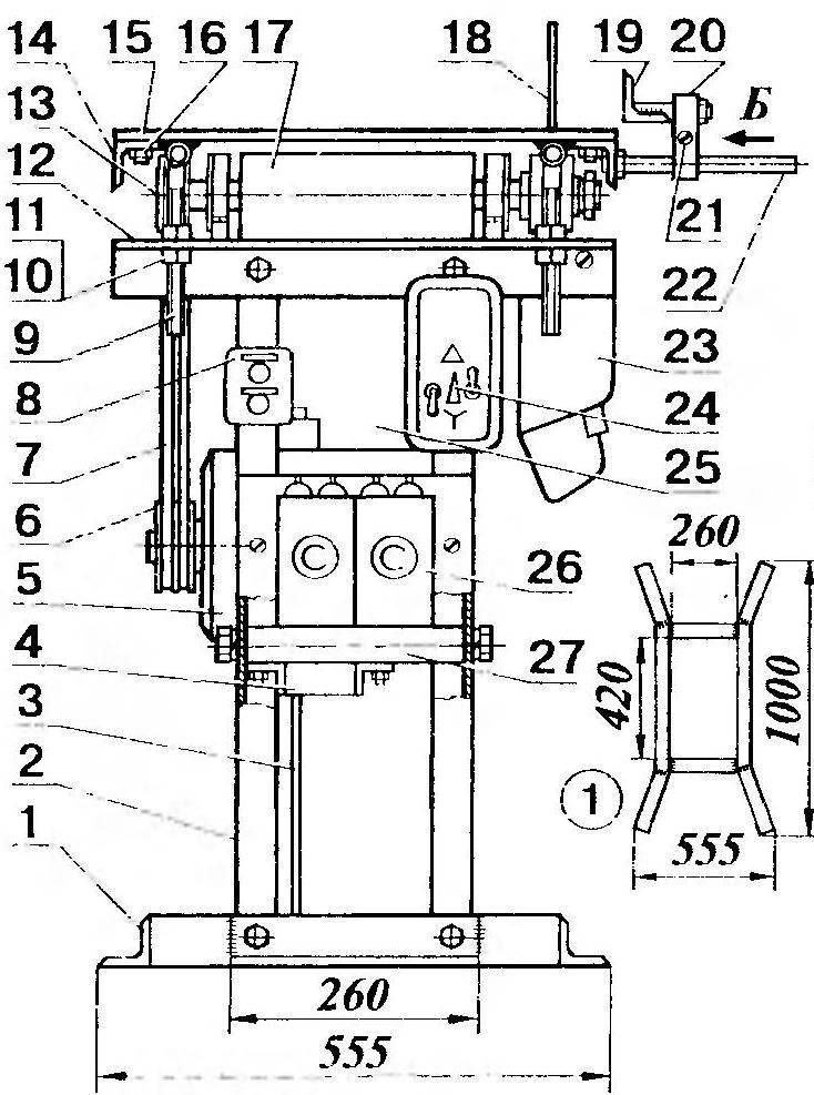
1 support-base, 2 - rack (steel angle 40 × 40, 1.800, 4 pcs.), 3 - belt tension rod (steel bar 16, 1.350 with M16 thread at the ends), 4 - rotary engine platform, 5 - electric motor asynchronous three-phase AIR100S4UZ, 6 - two-strand drive pulley (s1 100), 7 - wedge-shaped belt (2 pcs.), 8 - control panel with "Start" and "Stop" buttons, 9 - table stand (4 pcs.), 10 - adjusting nut M16 with a lock nut (4 sets), 11 - Grover's washer (4 pcs.), 12 - frame, 13 - two-strand driven pulley (d 50), 14-spar of the table (steel angle 50 × 50, 1,700. 2 pcs. ), 15 - composite table cover (steel sheet 555 × 500, sb, 2 pcs.), 16 - M12 countersunk head screw (22 pcs.), 17 - rotary planer assembly, 18 - circular saw blade, 19 - ruler - limiter, 20 - composite clamp (2 pcs.), 21 - M8 screw (2 pcs.). 22 - guide with M16 thread at the end (2 pcs.), 23 - sawdust chute (aluminum, sheet sZ), 24 - magnetic starter with switch ("Star" - "Triangle") and two switches, 25 - chute for shavings (aluminum, sheet, s3), 26 - capacitor 100 microns x 400 V (2 pcs.), 27 - axis of the engine platform, 28 - wing nut M 16.

1 - M8 bolt with Grover's washer, 2 - clamping washer, 3 - driven double-strand pulley, 4 - bearing assembly cover (St5, 2 pcs.), 5 - M5 bolt (4 pcs.), 6 - bearing assembly housing (St5, 2 pcs.), 7 - ball bearing 206 (2 pcs.), 8 - planer knife (tool steel, 3 pcs.), 9 - Mb spacer bolt (9 pcs.), 10 - clamping bar (StZ, Zsht.), 11 - driven shaft (steel 45), 12 - spacer ring (St3), 13 - profile washer (StZ), 14 - circular saw blade, 15 - tightening washer (StZ), 16 - tightening ring (StZ), 17 - nut M24, 18 - Grover's puck.

The mode with the symbol "D" is work with increased power. They switch to it after the electric motor, having thoroughly accelerated, picks up the required speed in the “Y” mode. Then boldly increase the capacitance of the phase-shifting capacitor by additionally connecting another 100 microfarads using SA1. And only then, preventing strong starting currents, they switch the windings to the “triangle”, moving the BAZ to the “D” position.
It is easy to stop the engine in any of the modes. To do this, just click on the "Stop" button. Then the supply voltage to the coil winding of the magnetic starter will immediately stop, and it will de-energize the electric motor.
As for the SA4 "Reverse" switch, as practice has shown, it can not be installed. And the required direction of rotation is achieved in this case during commissioning by "reversing the ends" of one of the windings.
And one more remark regarding the features of the functioning of the scheme under consideration. After stopping the motor, both capacitors must be discharged. To do this, you just need to ... turn on SA1 and SA2.
It is time to consider the features of the operation of the machine itself as a whole. It is better to do this by referring to the illustrations.
First of all - adjustment of the height of the cut, as well as the thickness of the chip removal. The required results are achieved here ... by turning the screws. Special, adjusting, with subsequent fixation with a lower nut.
Changing the tilt of the table (when sawing at an angle other than a straight one) is carried out by simply raising (or lowering) the posts (on the opposite side of the saw blade) to the required height. Optimum shaft speeds (1500 rpm for sawing and approximately 3500 rpm for planing the starting material) are achieved by appropriate selection of the diameters of the driving and driven pulleys.
Other possibilities of the machine? They are directly dependent on which tool is on the working shaft. For example, using various cutters, you can successfully select grooves, quarters. Replacing the saw blade with a cutting wheel, we get a reliable mechanical metal cutter. And with the installation of emery - a machine for sharpening tools.
But all this requires accuracy. And, of course, the strictest, strict observance of safety regulations. In particular, when installing the shaft on the bed frame, it must be fixed rigidly, without distortion. Having tightened the bolts first on one support, make sure that the other has not risen above the frame and is not excessively pressed against it. Then you need to approach the tightening of the bolts on the second support with the same precaution. Correct the skew immediately by placing metal gaskets under the supports. Bearings must be filled with refractory grease. Make sure that sawdust and shavings do not get into them in any case.
No less care should be taken with the planer. The knives of this working body must be securely fastened with bolts. It is worth recalling that when the planer is not in use, it must be closed with a special metal cover (not shown in the figure).
In order to avoid any surprises, the nuts for fastening the “circular” must certainly be with Grover's washers, and it will not hurt the rest of the threaded connections to have proper tightening. Before working on the machine, you should check how well everything is fixed. Make sure that the V-belt transmission is reliable by turning the shaft itself several times behind the drive belt. The latter should rotate easily, without jamming. And only then you can start working.
B. POTAPOV, Ryazan