How to make a robot at home: a step-by-step action plan. Small homemade robot Make a robot at home
Read also
Even those who have just picked up a soldering iron can make the simplest robot.
Mostly our robot (depending on the design) will run towards the light or, on the contrary, run away from it, run forward in search of a ray of light, or back away like a mole.
For our future" artificial intelligence"you will need:
- Chip L293D
- Small electric motor M1 (can be pulled out of toy cars)
- Phototransistor and 200 ohm resistor.
- Wires, a battery and, of course, the platform itself where it will all be placed.
If you add a couple more bright LEDs to the design, you can easily achieve that the robot will simply run after your hand or even follow a light or dark line. Our creation will be a typical representative of BEAM class robots. The principle of behavior of such robots is based on “photoreception”, that is, light in in this case, will act as a source of information.
Our robot will move forward when a beam of light hits it. This behavior of the device is called “photokinesis” - a non-directional increase or decrease in mobility in response to changes in light levels.
Our device, as mentioned above, used a phototransistor n-p-n structures– PTR-1 as a photosensor. Here you can use not only a phototransistor, but also a photoresistor or photodiode, since the operating principle of all elements is the same.
The figure immediately shows wiring diagram robot If you are not yet sufficiently familiar with technical symbols, then, based on this diagram, it will not be difficult to understand the principles of designation and connection of elements to each other.
GND. Wires connecting various elements circuits with “ground” (the negative pole of the power supply) are usually not completely depicted on the diagrams. Instead, a small line is drawn to indicate the connection to the “ground”. Sometimes, next to the dash they write “GND” - from English. the words "ground" - earth.
Vcc. This designation indicates that through this part the circuit is connected to the power source - Positive pole! Sometimes on diagrams the current rating is often written instead of these letters. In this case +5V.
Operating principle of the robot.
When a light ray hits the phototransistor (indicated in the diagram as PRT1), a positive signal appears at the output of the INPUT1 microcircuit, which causes the M1 motor to work. And vice versa, when the light beam stops illuminating the phototransistor, the signal at the output of the INPUT1 microcircuit disappears, therefore, the motor stops.
Resistor R1 in this circuit is designed to compensate for the current passing through the phototransistor. The resistor value is 200 Ohms - of course, you can solder resistors with other values here, but you should remember that the sensitivity of the phototransistor, and therefore the performance of the robot itself, will depend on the value.
If the resistor value is large, then the robot will respond only to a very bright beam of light, and if it is small, then the sensitivity will be much higher.
In short, you should not use resistors with a resistance of less than 100 Ohms in this circuit, otherwise the phototransistor may simply overheat and fail.
Digital and analog multimeters Taking measurements Reading circuits: shielding, grounding Reading circuits: lamps and photocells Repair electric kettle DIY image projection clock
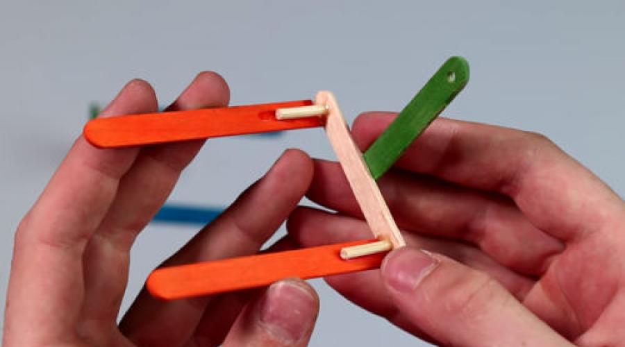
The host of the channel “Textbook of Mastery” showed clearly how to make a walking mini robot. First of all, let's make the paws. We fasten two ice cream sticks together, measure 6 centimeters and immediately put two marks where the holes will be. We remove all excess with a scalpel, and sand the cut area. Using a drill, we drill two holes according to the marks.
We take two more sticks, secure them with tape, measure 6 centimeters and cut them off with a hacksaw. There is no need to round the edge. We make a hole on this workpiece only on one side. We will glue these blanks right in the middle of the shelf with rounded edges. Please note that they must be perpendicular. Prepare four 3-centimeter pieces of wooden skewers in advance. Insert into the bottom hole. Using superglue, glue two 8 cm pieces to a skewer. Use a ruler to maintain a 90 degree angle. See what happens. We make the second paw in exactly the same way. As you can see, everything is clear and in home environment it's not difficult to do all this.

We will also need a plastic toy ball. In the lower part of the ball, using a hacksaw, we make two indentations for a wooden skewer. We twist the top part with a marker and mark where the cut will begin. Unscrew it along the thread and mark it again. Using a hacksaw, carefully make cuts between the marks. We select everything. When we unscrew or tighten the ball, the hole will always be open.
We take a low-speed gearbox motor. We attach a ready-made contact to it. You can get by with ordinary wiring. Cut a piece of the leg from the lollipop. We heat one end well and flatten it. We also heat the second end and put it on the gearbox shaft. At the bottom of the plastic ball, measure and glue a piece of an ice cream stick. This will be a stand for the gear motor. Let the superglue harden a little and apply hot glue liberally on top. We install the motor and fill the housings with hot glue. It should not get on the gearbox. Leave the ball with the motor aside. We make 2 centimeter blanks with a hole in the middle. To avoid burrs, we process the edge sandpaper. Take a ruler and make two marks at a distance of 1 cm. Drill two holes along the marks and cut them in a semicircle with a scalpel. We process the edges.
Continued on video from minute five. Here we show in detail how to make an interesting mini robot at home.
The simplest robot at home
To make the simplest thing we need a motor, two pieces of wire, a clothespin, Charger from the phone. First you need to attach the wire to the motor. After that, once the glue has hardened, take pliers and bend the legs. Now you can move them apart so that the robot stands more confidently. Now we solder the contacts on the charger to the plus and minus.
Next is a video from the “No Feelings” channel, which shows how to create this robot toy.
Now you can test this simple mini robot. To make it move, we put a clothespin on the rotor. That's all! The robot is running.
Mini robot from a kit at home
The Alphadroid channel told how to make a mini robot at home.
To assemble a walker you need a large number of components. The platform was used for self-assembly"Droid." In addition to the parts that can be purchased on the radio market, the kit contains additional necessary elements.
Watch the video of the Alpha Mods channel.
Kit contents: panels with parts for assembling the case, battery compartment, 4 full sets of servos, 30 nuts, M 3 screws and nuts, 2 self-tapping screws, ultrasonic distance sensor, cable, magnetized screwdriver, assembly instructions.
The robot body is made of wood, MDF. Includes 5 plates with parts for the body, machined laser engraver. The robot is equipped with an ultrasonic sensor, this will help it navigate in space. On the first pages of the instructions, body panels are drawn on a scale of 1:1. It is necessary to take real plates and number them as shown in the figure.
First of all, you need to take part D1 and D4, as well as a pair of M3*10 screws. Carefully remove the parts from the plate and screw them to each other. Take D5 and servos. We screw it to D5 using the self-tapping screws that come with the kit. We take the first and second blanks and connect them using D3. IN wooden parts There are grooves and they fit into each other. We take the nuts and place them in the places provided for them. These were the legs and feet of a robot. Moving on to D2 and the servo sleeves. We fix the sleeve on the bar. The strap is put on.
We carry out calibration: turn the drive to the side, pull out the bar, reinsert it and turn it again until the bar rests. Once again we remove the straps and put them in the final position: so that D2 touches D3, or is as close as possible to it. We return the drive to initial position. At this point the calibration is complete. Take support D10 and install it on D1 and D2. D1 is not clamped all the way using the locknut. What has now been installed is a socket for servos; the remaining two are placed on the corresponding sockets. There is a fixation bar - D11.
Calibration: put on the hangers and turn them all the way, remove the shoulders and install them in vertical position, set the angle to 90 degrees, and finally shoot. The legs are ready. To assemble the head: D7, D14 and 4 bolts m3*12 mm.
Today we will tell you how to make a robot from available materials. The resulting “high-tech android,” although it will be small size and is unlikely to be able to help you with housework, but will certainly amuse both children and adults.
Necessary materials
To make a robot with your own hands, you don’t need knowledge nuclear physics. This can be done at home from ordinary materials, which are always at hand. So what we need:- 2 pieces of wire
- 1 motor
- 1 AA battery
- 3 push pins
- 2 pieces of foam board or similar material
- 2-3 heads of old toothbrushes or a few paper clips

1. Attach the battery to the motor
Using a glue gun, attach a piece of foam cardboard to the motor housing. Then we glue the battery to it.


Place a couple of drops of glue on the very end of the destabilizer, or attach some decorative element- this will add individuality to our creation and increase the amplitude of its movements.

3. Legs
Now you need to equip the robot with lower limbs. If you use toothbrush heads for this, glue them to the bottom of the motor. You can use the same foam board as a layer.


5. Battery connection
Using a heat gun, glue the wire to one end of the battery. You can choose any of the two wires and either side of the battery - polarity does not matter in this case. If you're good at soldering, you can also use soldering instead of glue for this step.

6. Eyes
A pair of beads, which we attach with hot glue to one end of the battery, are quite suitable as the robot’s eyes. At this step, you can show your imagination and come up with appearance eye at your discretion.
7. Launch
Now let's bring our homemade project to life. Take the free end of the wire and attach it to the unoccupied battery terminal using adhesive tape. You should not use hot glue for this step because it will prevent you from disconnecting the motor if necessary.Today we will tell you how to make a robot from available materials. The resulting “high-tech android,” although small in size and unlikely to help you with housework, will certainly amuse both children and adults.
Necessary materials
In order to make a robot with your own hands, you do not need knowledge of nuclear physics. This can be done at home from ordinary materials that you always have on hand. So what we need:
- 2 pieces of wire
- 1 motor
- 1 AA battery
- 3 push pins
- 2 pieces of foam board or similar material
- 2-3 heads of old toothbrushes or a few paper clips

1. Attach the battery to the motor
Using a glue gun, attach a piece of foam cardboard to the motor housing. Then we glue the battery to it. 

2. Destabilizer
This step may seem confusing. However, to make a robot, you need to make it move. We put a small oblong piece of foam cardboard on the motor axis and secure it with a glue gun. This design will give the motor an imbalance, which will set the entire robot in motion.

Place a couple of drops of glue on the very end of the destabilizer, or attach some decorative element - this will add individuality to our creation and increase the amplitude of its movements.

3. Legs
Now you need to equip the robot with lower limbs. If you use toothbrush heads for this, glue them to the bottom of the motor. You can use the same foam board as a layer.


4. Wires
The next step is to attach our two pieces of wire to the motor contacts. You can simply screw them on, but it would be even better to solder them, this will make the robot more durable.

5. Battery connection
Using a heat gun, glue the wire to one end of the battery. You can choose any of the two wires and either side of the battery - polarity does not matter in this case. If you're good at soldering, you can also use soldering instead of glue for this step.


6. Eyes
A pair of beads, which we attach with hot glue to one end of the battery, are quite suitable as the robot’s eyes. At this step, you can show your imagination and come up with the appearance of the eyes at your discretion.

7. Launch
Now let's bring our homemade project to life. Take the free end of the wire and attach it to the unoccupied battery terminal using adhesive tape. You should not use hot glue for this step because it will prevent you from disconnecting the motor if necessary.

The robot is ready!

Here's what ours might look like homemade robot, if you show more imagination:


And finally the video:
Based on materials from techcult
Make a robot very simple Let's figure out what it takes to create a robot at home, in order to understand the basics of robotics.
Surely, after watching enough movies about robots, you have often wanted to build your own comrade in battle, but you didn’t know where to start. Of course, you won't be able to build a bipedal Terminator, but that's not what we're trying to achieve. Anyone who knows how to hold a soldering iron correctly in their hands can assemble a simple robot and does not need deep knowledge, although they won't hurt. Amateur robotics is not much different from circuit design, only much more interesting, because it also involves areas such as mechanics and programming. All components are easily available and are not that expensive. So progress does not stand still, and we will use it to our advantage.
Introduction
So. What is a robot? In most cases this automatic device, which reacts to any actions environment. Robots can be controlled by humans or perform pre-programmed actions. Typically, the robot is equipped with a variety of sensors (distance, rotation angle, acceleration), video cameras, and manipulators. The electronic part of the robot consists of a microcontroller (MC) - a microcircuit that contains a processor, a clock generator, various peripherals, RAM and permanent memory. There are a huge number of different microcontrollers in the world for different areas applications and on their basis you can assemble powerful robots. For amateur buildings wide application found AVR microcontrollers. They are by far the most accessible and on the Internet you can find many examples based on these MKs. To work with microcontrollers you need to be able to program in assembler or C and have basic knowledge in digital and analog electronics. In our project we will use C. Programming for MK is not much different from programming on a computer, the language syntax is the same, most functions are practically no different, and new ones are quite easy to learn and convenient to use.
What do we need
To begin with, our robot will be able to simply avoid obstacles, that is, repeat the normal behavior of most animals in nature. Everything we need to build such a robot can be found in radio stores. Let's decide how our robot will move. I think the most successful are the tracks that are used in tanks; this is the most convenient solution, because the tracks have greater maneuverability than the wheels of a vehicle and are more convenient to control (to turn, it is enough to rotate the tracks in different sides). Therefore, you will need any toy tank whose tracks rotate independently of each other, you can buy one at any toy store at a reasonable price. From this tank you only need a platform with tracks and motors with gearboxes, the rest you can safely unscrew and throw away. We also need a microcontroller, my choice fell on ATmega16 - it has enough ports for connecting sensors and peripherals and in general it is quite convenient. You will also need to purchase some radio components, a soldering iron, and a multimeter.
Making a board with MK
In our case, the microcontroller will perform the functions of the brain, but we will not start with it, but with powering the robot’s brain. Proper nutrition- a guarantee of health, so we will start with how to properly feed our robot, because this is where novice robot builders usually make mistakes. And in order for our robot to work normally, we need to use a voltage stabilizer. I prefer the L7805 chip - it is designed to produce a stable 5V output voltage, which is what our microcontroller needs. But due to the fact that the voltage drop on this microcircuit is about 2.5V, a minimum of 7.5V must be supplied to it. Together with this stabilizer, electrolytic capacitors are used to smooth out voltage ripples and a diode is necessarily included in the circuit to protect against polarity reversal.
Now we can move on to our microcontroller. The case of the MK is DIP (it’s more convenient to solder) and has forty pins. On board there is an ADC, PWM, USART and much more that we will not use for now. Let's look at a few important nodes. The RESET pin (9th leg of the MK) is pulled up by resistor R1 to the “plus” of the power source - this must be done! Otherwise, your MK may unintentionally reset or, more simply put, glitch. Also a desirable measure, but not mandatory, is to connect RESET through the ceramic capacitor C1 to ground. In the diagram you can also see a 1000 uF electrolyte; it saves you from voltage dips when the engines are running, which will also have a beneficial effect on the operation of the microcontroller. Quartz resonator X1 and capacitors C2, C3 should be located as close as possible to pins XTAL1 and XTAL2.
I won’t talk about how to flash MK, since you can read about it on the Internet. We will write the program in C; I chose CodeVisionAVR as the programming environment. This is a fairly user-friendly environment and is useful for beginners because it has a built-in code creation wizard.

Motor control
An equally important component in our robot is the motor driver, which makes it easier for us to control it. Never and under no circumstances should motors be connected directly to the MK! In general, powerful loads cannot be controlled directly from the microcontroller, otherwise it will burn out. Use key transistors. For our case, there is a special chip - L293D. In such simple projects, always try to use this particular chip with the “D” index, as it has built-in diodes for overload protection. This microcircuit is very easy to control and is easy to get in radio stores. It is available in two packages: DIP and SOIC. We will use in DIP package due to the ease of installation on the board. L293D has separate power supply for motors and logic. Therefore, we will power the microcircuit itself from the stabilizer (VSS input), and the motors directly from the batteries (VS input). L293D can withstand a load of 600 mA per channel, and it has two of these channels, that is, two motors can be connected to one chip. But to be on the safe side, we will combine the channels, and then we will need one micra for each engine. It follows that the L293D will be able to withstand 1.2 A. To achieve this, you need to combine the micra legs, as shown in the diagram. The microcircuit works as follows: when a logical “0” is applied to IN1 and IN2, and a logical one is applied to IN3 and IN4, the motor rotates in one direction, and if the signals are inverted - a logical zero is applied, then the motor will begin to rotate in the other direction. Pins EN1 and EN2 are responsible for turning on each channel. We connect them and connect them to the “plus” of the power supply from the stabilizer. Since the microcircuit heats up during operation, and installing radiators on this type of case is problematic, heat dissipation is provided by GND legs - it is better to solder them on a wide contact pad. That's all you need to know about engine drivers for the first time.
Obstacle sensors
So that our robot can navigate and not crash into everything, we will install two infrared sensor. The simplest sensor consists of an IR diode that emits in the infrared spectrum and a phototransistor that will receive the signal from the IR diode. The principle is this: when there is no obstacle in front of the sensor, the IR rays do not hit the phototransistor and it does not open. If there is an obstacle in front of the sensor, then the rays are reflected from it and hit the transistor - it opens and current begins to flow. The disadvantage of such sensors is that they can react differently to various surfaces and are not protected from interference - the sensor may accidentally trigger from extraneous signals from other devices. Modulating the signal can protect you from interference, but we won’t bother with that for now. For starters, that's enough.

Robot firmware
To bring the robot to life, you need to write firmware for it, that is, a program that would take readings from sensors and control the motors. My program is the simplest, it does not contain complex structures and everyone will understand. The next two lines include header files for our microcontroller and commands for generating delays:
#include
#include
The following lines are conditional because the PORTC values depend on how you connected the motor driver to your microcontroller:
PORTC.0 = 1; PORTC.1 = 0; PORTC.2 = 1; PORTC.3 = 0; The value 0xFF means that the output will be log. "1", and 0x00 is log. "0". With the following construction we check whether there is an obstacle in front of the robot and on which side it is: if (!(PINB & (1< If light from an IR diode hits the phototransistor, then a log is installed on the microcontroller leg. “0” and the robot starts moving backward to move away from the obstacle, then turns around so as not to collide with the obstacle again and then moves forward again. Since we have two sensors, we check for the presence of an obstacle twice - on the right and on the left, and therefore we can find out which side the obstacle is on. The command "delay_ms(1000)" indicates that one second will pass before the next command begins to execute. I've covered most of the aspects that will help you build your first robot. But robotics doesn't end there. If you assemble this robot, you will have a lot of opportunities to expand it. You can improve the robot's algorithm, such as what to do if the obstacle is not on some side, but right in front of the robot. It also wouldn’t hurt to install an encoder - a simple device that will help you accurately position and know the location of your robot in space. For clarity, it is possible to install a color or monochrome display that can show useful information - battery charge level, distance to obstacles, various debugging information. It wouldn't hurt to improve the sensors - installing TSOPs (these are IR receivers that perceive a signal only of a certain frequency) instead of conventional phototransistors. In addition to infrared sensors, there are ultrasonic sensors, which are more expensive and also have their drawbacks, but have recently been gaining popularity among robot builders. In order for the robot to respond to sound, it would be a good idea to install microphones with an amplifier. But what I think is really interesting is installing the camera and programming machine vision based on it. There is a set of special OpenCV libraries with which you can program facial recognition, movement according to colored beacons and many other interesting things. It all depends only on your imagination and skills. List of components: ATmega16 in DIP-40 package> L7805 in TO-220 package L293D in DIP-16 housing x2 pcs. resistors with a power of 0.25 W with ratings: 10 kOhm x 1 pc., 220 Ohm x 4 pcs. ceramic capacitors: 0.1 µF, 1 µF, 22 pF electrolytic capacitors: 1000 µF x 16 V, 220 µF x 16 V x 2 pcs. diode 1N4001 or 1N4004 16 MHz quartz resonator IR diodes: any two of them will do. phototransistors, also any, but responding only to the wavelength of infrared rays Firmware code: At the moment my robot is almost complete. It is equipped with a wireless camera, a distance sensor (both the camera and this sensor are installed on a rotating tower), an obstacle sensor, an encoder, a signal receiver from the remote control and an RS-232 interface for connecting to a computer. It operates in two modes: autonomous and manual (receives control signals from the remote control), the camera can also be turned on/off remotely or by the robot itself to save battery power. I am writing firmware for apartment security (transferring images to a computer, detecting movements, walking around the premises).Conclusion
