How to calculate the rated current of a circuit breaker? How many amperes to install an introductory machine in a private house? How many machines are there?
Read also
To ensure reliable cable protection using a circuit breaker, you need to take into account some of the operating features of this device and make the correct selection. The fact is that the current (I n), which is indicated in the marking of the machine, is actually the operating current, and its excess in a certain range does not cause an immediate shutdown of the network.
Ratings of machines for protecting electrical cables
For example, if the marking is C25, then this means that a current of 25A can flow through this circuit for an unlimited time. If the excess is up to 13% (28.5A), then a shutdown may occur after more than an hour of operation, up to 45% (36.25A) - in less than an hour. To guarantee network protection, it is important that the increased current does not exceed the permissible current in the cable.
Such an algorithm for the operation of the machine, on the one hand, will reduce the likelihood of false positives, but on the other hand, it requires a more thoughtful approach to the choice of machine.
Choosing the right circuit breaker is not an easy task, but its solution determines the safe operation of a house or apartment and the reduction of material costs.
Options
Rated current (I n)
Automatic switches have a standardized range of rated currents, this is reflected in GOST R 50345–99, the data is summarized in a table. These are long-term currents flowing through the machine and not causing it to turn off. Using the table, you can select the rated current of the circuit breaker. It shows the standard range of rated currents (I n) for automatic machines used in Russia.
Standardized range of rated currents (In) for automatic machines
| Rated current A | |||||||||
|---|---|---|---|---|---|---|---|---|---|
| 0.5 | 1 | 1.6 | 2 | 2.5 | 3 | 4 | 5 | 6.3 (or 6) | |
| 8 | 10 | 16 | 25 | 31.5 (or 32) | 40 | 50 | 63 | ||
| 80 | 100 | 125 | 160 | 200 | 250 | 320 | 400 | 500 | 630 |
| 800 | 1000 | 1600 | 2000 | 2500 | 4000 | 5000 | 6300 |
However, the shutdown time is influenced by the ambient temperature and the method of installation of the circuit breaker. Thus, an increase in air temperature at the location where the machine is installed shortens this period, while a decrease lengthens it. A single switch installed has a longer period, while one installed in a group has a shorter period, due to the influence of neighboring circuit breakers.
The table below provides information on currents leading to long-term tripping and will allow you to select the required rating. These are normalized currents according to GOST.
Standardized currents according to GOST for choosing the rating of the machine
| Character ristics triggered- vending machines type B, C, D | Machine denomination | ||||||||
|---|---|---|---|---|---|---|---|---|---|
| 6A | 10A | 13A | 16A | 20A | 25A | 32A | 40A | 50A | |
| Turn off reading NOT EARLIER, than 1 hour (1.13*In) | 6.78 A | 11.3 A | 14.69 A | 18.08 A | 22.6 A | 28.25 A | 36.16 A | 45.2 A | 56.5 A |
| Turn off reading NOT MORE, than 1 hour (1.45*In) | 8.7 A | 14.5 A | 18.85 A | 23.2 A | 29 A | 36.25 A | 46.4 A | 58 A | 72.5 A |
Using the table below, you can select a circuit breaker based on the shutdown current. For example, it is known that a cable in open wiring with a copper conductor cross-section of 4 mm 2 has a permissible current of 30A (t. 1.3.4-1.3.8. PUE). We find in the table the nearest lower shutdown current, this is 29A, which means we need a C20 circuit breaker. If you choose a machine with a rated current of C25, then the long-term flowing current in the cable will be 36.25A; the machine’s shutdown time can reach 1 hour. During this time, the cable can heat up to a significant temperature, which will cause the insulation to melt. If a repetition of such a situation is not excluded, it will certainly lead to an accident.
It is also impossible without complex measurements to accurately determine at what load current this or that particular instance will operate, but there is a corridor in which any instance of this rating is guaranteed to operate.
Time-current characteristics
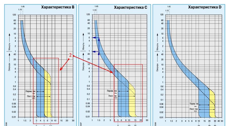
These characteristics are presented in the form of a graph, from which you can quite accurately determine the current and time when the device is guaranteed to turn off.

Graphs for determining the time to turn off the machine
For example, you can find out after what period of time a type C machine will turn off if a current flows through it one and a half times more than the rated current, i.e. I/I n = 1.5. We draw a vertical line on the graph so that it intersects the range of values and from the points of intersection of this line with the blue zone we draw horizontal lines to the Y axis.
On the Y axis we see the time: minimum - 50 seconds, maximum - around 6 minutes. This means that with double the current, this cable will operate under such a load for up to 6 minutes.
To determine the breaking currents for other types, B or D, horizontal lines should be drawn to the Y axis from the corresponding areas.
In the event of a short circuit, the machines operate very reliably, turning off the network in less than 0.1 seconds; during such a period of time the cable does not have time to noticeably heat up.
If an emergency shutdown occurs, do not rush to turn on the machine; first turn off powerful appliances, especially heating ones: iron, boiler, electric stove, microwave, etc. Turn on the machine after 5–10 minutes; if a repeated shutdown occurs, it is better to call a specialist.
Cables GOST 31996–2012
When choosing a machine, it is necessary to take into account the characteristics of the cables. The most important is the permissible current (I add). It shows at what maximum current the cable can operate throughout its entire service life. This table from the PUE contains information about permissible cable currents depending on the material and conditions of cable laying.
Permissible currents for cable depending on materials
| Open wiring | Seche- tion cable la, mm2 | Closed wiring | ||||||||||
|---|---|---|---|---|---|---|---|---|---|---|---|---|
| Copper | Aluminum | Copper | Aluminum | |||||||||
| Current A | Power- ness, kW | Current A | Power- ness, kW | Current A | Power- ness, kW | Current A | Power- ness, kW |
|||||
| 220 V | 380 V | 220 V | 380 V | 220 V | 380 V | 220 V | 380 V | |||||
| 11 | 2.4 | - | - | - | - | 0.5 | - | - | - | - | - | - |
| 15 | 3.3 | - | - | - | - | 0.75 | - | - | - | - | - | - |
| 17 | 3.7 | 6.4 | - | - | - | 1 | 14 | 3 | 5.3 | - | - | - |
| 23 | 5 | 8.7 | - | - | - | 1.5 | 15 | 3.3 | 5.7 | - | - | - |
| 26 | 5.7 | 9.8 | 21 | 4.6 | 7.9 | 2 | 19 | 4.1 | 7.2 | 14 | 3 | 5.3 |
| 30 | 6.6 | 11 | 24 | 5.2 | 9.1 | 2.5 | 21 | 4.6 | 7.9 | 16 | 3.5 | 6 |
| 41 | 9 | 15 | 32 | 7 | 12 | 4 | 27 | 5.9 | 10 | 21 | 4.6 | 7.9 |
| 50 | 11 | 19 | 39 | 8.5 | 14 | 6 | 34 | 7.4 | 12 | 26 | 5.7 | 9.8 |
| 80 | 17 | 30 | 60 | 13 | 22 | 10 | 50 | 11 | 19 | 38 | 8.3 | 14 |
| 100 | 22 | 38 | 75 | 16 | 28 | 16 | 80 | 17 | 30 | 55 | 12 | 20 |
| 140 | 30 | 53 | 105 | 23 | 39 | 25 | 100 | 22 | 38 | 65 | 14 | 24 |
| 170 | 37 | 64 | 130 | 28 | 49 | 35 | 130 | 29 | 51 | 75 | 16 | 28 |
From this table you can find the required cable cross-section and permissible current depending on the wiring conditions, open or buried. For example, the power of all appliances in the apartment is 9 kW. For open single-phase copper wiring, the wire cross-section is 4 mm 2, current 41A, for closed - the nearest higher power value is 11 kW, cross-section 10 mm 2, current 50A. The nearest lower rating of the circuit breaker is 32A.
If there is doubt about the quality of the electrical wiring, then it is better to exercise caution and choose a machine with a rating lower than the value in the table.
The residential network has a branched structure: a current of different strength will flow in each branch, so the wires have different cross-sections. If you install one circuit breaker only at the entrance, it will not be able to protect individual sections of the wiring from overload. If the entire network is laid with a cable of the same cross-section, then this is an unjustified financial expense. The best solution would be to install the appropriate current on each section of the machine. The figure shows an approximate structure.

Installation of machines for the appropriate current
The figure clearly shows the load on each section and the cross-section of the wire. By installing appropriate circuit breakers, you can reliably protect the entire network from short circuits or overloads. In addition, at any time it is possible to select and disable one or another section, maintaining the functionality of the rest of the network.
When using powerful asynchronous motors in everyday life, especially 3-phase ones, for example, power tools, it is advisable to turn them on through a separate machine, since they have a large starting current, and when operating through a common machine, a power outage may occur even during normal operation of the equipment.
Selection of section. Video
You can learn in detail about the choice of cable cross-section and machine rating from this video.
If the selection of a circuit breaker is carried out for an existing network, then first of all you need to know the cross-section of the wiring, and then make a choice based on it. If the network has not yet been laid, then you need to start by calculating the possible load, taking into account all the household appliances that you plan to connect. The wiring lasts 20-30 years if used properly, during which time, most likely, new appliances will appear in everyday life, so a power reserve of 20 percent should be provided.
To organize a trouble-free in-house power supply, it is necessary to allocate separate branches. Each line must be equipped with its own protection device that protects the cable insulation from melting. However, not everyone knows which device to buy. Do you agree?
You will learn everything about choosing automatic machines based on load power from the article we presented. We will tell you how to determine the rating to find a switch of the required class. Taking into account our recommendations guarantees the purchase of the required devices that can eliminate dangerous situations during the operation of the wiring.
Electricity supply organizations connect houses and apartments by carrying out work on connecting the cable to the switchboard. All installations of wiring in the premises are carried out by its owners or hired specialists.
To select a circuit breaker to protect each individual circuit, you need to know its rating, class and some other characteristics.
Basic parameters and classification
Household machines are installed at the entrance to a low-voltage electrical circuit and are designed to solve the following problems:
- manual or electronic activation or de-energization of an electrical circuit;
- circuit protection: current cut-off during minor long-term overload;
- circuit protection: instantaneous shutdown of current in case of short circuit.
Each switch has a characteristic, expressed in amperes, which is called ( I n) or “face value”.
The essence of this value is easier to understand using the coefficient of excess of the nominal value:
K = I / I n,
where I is the actual current strength.
- K< 1.13: отключение (расцепление) не произойдет в течение 1 часа;
- K > 1.45: shutdown will occur within 1 hour.
These parameters are fixed in clause 8.6.2. GOST R 50345-2010. To find out how long it will take for a shutdown to occur at K>1.45, you need to use a graph reflecting the time-current characteristic of a specific machine model.
If the current exceeds the rated value of the switch by 2 times for a long time, the opening will occur within a period of 8 seconds to 4 minutes. The response speed depends on the model settings and the ambient temperature
Also, each type of circuit breaker has a defined current range ( I a), at which the instantaneous release mechanism is activated:
- class “B”: I a = (3 * I n .. 5 * I n ];
- class “C”: I a = (5 * I n .. 10 * I n ];
- class “D”: I a = (10 * I n .. 20 * I n ].
Type “B” devices are used mainly for lines that are of considerable length. In residential and office premises, class “C” circuit breakers are used, and devices marked “D” protect circuits where there is equipment with a high starting current coefficient.
The standard line of household machines includes devices with ratings of 6, 8, 10, 16, 20, 25, 32, 40, 50 and 63 A.
Structural design of releases
In modern times there are two types of releases: thermal and electromagnetic.
A bimetallic release has the shape of a plate created from two conductive metals with different thermal expansion. This design, when exceeding the nominal value for a long time, leads to heating of the part, its bending and the activation of the circuit breaking mechanism.
For some machines, you can use the adjusting screw to change the parameters of the current at which the shutdown occurs. In the past, this technique was often used to “fine-tune” a device, but this procedure requires in-depth specialized knowledge and several tests.

By rotating the adjusting screw (highlighted with a red rectangle) counterclockwise, you can achieve a longer response time for the thermal release
Now on the market you can find many models of standard ratings from different manufacturers, whose time-current characteristics are slightly different (but at the same time comply with regulatory requirements). Therefore, it is possible to select a machine with the required “factory” settings, which eliminates the risk of incorrect calibration.
An electromagnetic release prevents overheating of the line as a result of a short circuit. It reacts almost instantly, but the current value must be several times higher than the nominal value. Structurally, this part is a solenoid. The overcurrent generates a magnetic field that moves the core, breaking the circuit.
Compliance with selectivity principles
If there is a branched electrical circuit, it is possible to organize protection in such a way that in the event of a short circuit, only the branch on which the emergency situation occurs is disconnected. For this purpose, the principle of switch selectivity is used.

A visual diagram showing the operating principle of a circuit breaker system with an implemented function of selectivity (selectivity) of operation when a short circuit occurs
To ensure selective shutdown, instantaneous cutoff circuit breakers are installed at the lower stages, breaking the circuit in 0.02 - 0.2 seconds. The switch located at a higher stage either has an operation delay of 0.25 - 0.6 s or is made according to a special “selective” circuit in accordance with the DIN VDE 0641-21 standard.
For guaranteed security, it is better to use machines from one manufacturer. For switches of a single model range, there are selectivity tables that indicate possible combinations.
The simplest installation rules
The section of the circuit that needs to be protected by a switch can be single- or three-phase, have a neutral, as well as a PE (“ground”) wire. Therefore, the machines have from 1 to 4 poles, to which the conductor is connected. When conditions for tripping are created, all contacts are disconnected simultaneously.

The machines in the panel are mounted on a specially designated DIN rail. It provides compact and safe connection, as well as convenient access to the switch
The machines are installed as follows:
- single-pole per phase;
- bipolar for phase and neutral;
- three-pole for 3 phases;
- four-pole for 3 phases and neutral.
However, it is prohibited to do the following:
- install single-pole circuit breakers to neutral;
- insert PE wire into the machine;
- install three single-pole ones instead of one three-pole circuit breaker, if at least one three-phase consumer is connected to the circuit.
All these requirements are specified in the PUE and must be followed.
In every house or room to which electricity is supplied, an introductory machine is installed. Its nominal value is determined by the supplier and this value is specified in the electricity connection agreement. The purpose of such a switch is to protect the area from the transformer to the consumer.
After the input circuit breaker, a meter (single- or three-phase) and is connected to the line, the functions of which differ from the operation of the automatic and differential switch.
If the room is wired into several circuits, then each of them is protected by a separate circuit breaker, the power of which is . Their ratings and classes are determined by the owner of the premises, taking into account the existing wiring or power of connected devices.

The electricity meter and circuit breakers are installed in a distribution board that meets all safety requirements and can easily be integrated into the interior of the room
When choosing a location, you must remember that the properties of the thermal release are affected by air temperature. Therefore, it is advisable to place the rail with machines inside the room itself.
Calculation of the required denomination
The main protective function of the circuit breaker extends to the wiring, so the rating is selected based on the cable cross-section. In this case, the entire circuit must ensure the normal operation of the devices connected to it. Calculating system parameters is simple, but many nuances must be taken into account in order to avoid errors and problems.
Determination of the total power of consumers
One of the main parameters of the electrical circuit is the maximum possible power of the electricity consumers connected to it. When calculating this indicator, you cannot simply summarize the passport data of devices.
Active and nominal component
For any device powered by electricity, the manufacturer is required to indicate the active power ( P). This value determines the amount of energy that will be irrevocably converted as a result of the operation of the device and for which the user will pay on the meter.
But for devices with capacitors or an inductor, there is another power with a non-zero value, which is called reactive ( Q). It reaches the device and returns back almost instantly.
The reactive component does not participate in the calculation of used electricity, but together with the active component it forms the so-called “total” or “nominal” power ( S), which puts a load on the chain.

cos(f) – parameter with which you can determine the total (nominal) power from the active (consumed) power. If it is not equal to one, then it is indicated in the technical documentation for the electrical device
Increased starting currents
The next feature of some types of household appliances is the presence of transformers, electric motors or compressors. Such devices consume inrush (starting) current when starting up.
Its value can be several times higher than standard values, but the operating time at increased power is short and usually ranges from 0.1 to 3 seconds. Such a short-term surge will not trigger the thermal release, but the electromagnetic component of the switch, which is responsible for the short-circuit overcurrent, may react.
This situation is especially relevant for dedicated lines to which equipment such as woodworking machines are connected. In this case, you need to calculate the amperage and, perhaps, it makes sense to use a class “D” machine.
Taking into account the demand coefficient
For circuits that have a large amount of equipment connected and no device that consumes the largest portion of the current, use the demand factor ( ks). The point of using it is that all devices will not work at the same time, so summing up the rated powers will lead to an overestimated figure.

The demand coefficient for groups of electricity consumers is established in clause 7 of SP 256.1325800.2016. You can also rely on these indicators when independently calculating maximum power.
This coefficient can take a value equal to or less than one. Design power calculations ( P r) of each device occurs according to the formula:
P r = ks * S
The total rated power of all devices is used to calculate the circuit parameters. The use of the demand coefficient is advisable for office and small retail premises with a large number of computers, office equipment and other equipment powered from one circuit.
For lines with a small number of consumers, this coefficient is not used in its pure form. Those devices that are unlikely to be turned on simultaneously with more energy-consuming devices are removed from the power calculation.
So, for example, there is little chance of working in a living room with an iron and a vacuum cleaner at the same time. And for workshops with a small number of personnel, only 2-4 of the most powerful power tools are taken into account.
Current calculation
The machine is selected based on the maximum current value allowed in the circuit section. It is necessary to obtain this indicator, knowing the total power of electrical consumers and the voltage in the network.
According to GOST 29322-2014, from October 2015, the voltage value should be equal to 230 V for a regular network and 400 V for a three-phase network. However, in most cases, the old parameters are still in effect: 220 and 380 V, respectively. Therefore, for accurate calculations, it is necessary to take measurements using a voltmeter.
Another problem, especially relevant for, is the provision of electricity with insufficient voltage. Measurements at such problematic objects may show values outside the range defined by GOST.
Moreover, depending on the level of electricity consumption of your neighbors, the voltage value can vary greatly within a short time.
This creates a problem not only for the functioning of the devices, but also for. When the voltage drops, some devices simply lose power, and some that have an input stabilizer increase their electricity consumption.
It is difficult to carry out qualitative calculations of the required circuit parameters under such conditions. Therefore, you will either have to lay cables with a deliberately large cross-section (which is expensive), or solve the problem by installing an input stabilizer or connecting the house to another line.

The stabilizer is installed next to the switchboard. It often happens that this is the only way to obtain standard voltage values in the house
After the total power of electrical appliances has been found ( S) and found out the voltage value ( U), current calculation ( I) are carried out according to formulas that are a consequence of Ohm’s law:
I f = S / U f for single-phase network
I l = S / (1.73 * U l) for three-phase network
Here is the index “ f” means phase parameters, and “ l” – linear.
Most three-phase devices use the “star” connection type, and it is also according to this circuit that the transformer operates, delivering current to the consumer. With a symmetrical load, the linear and phase forces will be identical ( I l = If), and the voltage is calculated using the formula:
U l = 1.73 * U f
Nuances of selecting cable cross-section
The quality and parameters of wires and cables are regulated by GOST 31996-2012. According to this document, specifications are developed for manufactured products, where a certain range of values of basic characteristics is allowed. The manufacturer is obliged to provide a table of correspondence between the cross-section of the cores and the maximum safe current.

The maximum permissible current depends on the cross-section of the wires and the installation method. They can be laid hidden (in the wall) or open (in a pipe or box) way
It is necessary to select a cable in such a way as to ensure the safe flow of current corresponding to the calculated total power of electrical appliances. According to the PUE (electrical installation rules), the minimum used in residential premises must be at least 1.5 mm 2.
Standard sizes have the following values: 1.5; 2.5; 4; 6 and 10 mm 2.
Sometimes there is a reason to use wires with a cross-section one step larger than the minimum allowable. In this case, it is possible to connect additional devices or replace existing ones with more powerful ones without expensive and time-consuming work on laying new cables.
Calculation of machine parameters
For any circuit the following inequality must be satisfied:
I n<= I p / 1.45
Here I n is the rated current of the machine, and Ip– permissible current for wiring. This rule ensures guaranteed release when the permissible load is exceeded for a long time.

The inequality “In<= Ip / 1.45” является основным условием при комплектовании пары “автомат – кабель”. Пренебрежение этим правилом может привести к возгоранию проводки
In this case, the sequence of actions is as follows:
- Calculation of the total current strength of electrical appliances connected to the network.
- Select a machine with a denomination not less than the calculated value.
- Selection of cable cross-section according to the machine's rating.
- S = 4 kW; I = 4000 / 220 = 18 A;
- I n = 20 A;
- I p >= I n * 1.45 = 29 A; D = 4 mm 2.
If the wiring has already been laid, then the sequence of actions is different:
- Determination of the permissible current for a known cross-section and method of wiring according to the table provided by the manufacturer.
- Selection of circuit breaker.
- Calculation of the power of connected devices. Equipping a group of devices in such a way that the total load on the circuit is less than the nominal value.
Example. Let two single-core cables be laid openly, D = 6 mm 2, then:
- I p = 46 A;
- I n<= I p / 1.45 = 32 A;
- S = I n * 220 = 7.0 kW.
In point 2 of the last example there is a slight acceptable approximation. The exact value I n = I p / 1.45 = 31.7 A is rounded to a value of 32 A.
Choice between several denominations
Sometimes a situation arises when you can select several machines with different ratings to protect the circuit. For example, with a total power of electrical appliances of 4 kW (18 A), wiring with a copper core cross-section of 4 mm 2 was chosen with a reserve. For this combination, you can install 20 and 25 A switches.

If the electrical wiring diagram assumes the presence of multi-level protection, then you need to select circuit breakers so that the value of the rating of the higher one (in the figure on the right - 25 A) is greater than that of switches of lower levels
The advantage of choosing a switch with the highest rating is the ability to connect additional devices without changing the circuit elements. Most often this is what they do.
The choice of a machine with a lower rating is supported by the fact that its thermal release will respond faster to an increased current. The fact is that some devices may have a malfunction, which will lead to an increase in energy consumption, but not to the point of a short circuit.
For example, a failure of a washing machine motor bearing will lead to a sharp increase in current in the winding. If the machine quickly reacts to exceeding the permitted values and switches off, the motor will not burn out.
Conclusions and useful video on the topic
Design of a circuit breaker and its classification. The concept of time-current characteristics and selection of rating according to the cable cross-section:
Calculation of the power of devices and selection of a machine using the provisions of the PUE:
The choice of circuit breaker must be taken responsibly, since the safety of the electrical system at home depends on it. With all the many input parameters and calculation nuances, it is necessary to remember that the main protective function of the machine applies to the wiring.
Please write comments, ask questions, and post photos related to the topic of the article in the block below. Share useful information that may be useful to site visitors. Tell us about your own experience in choosing circuit breakers to protect country or home electrical wiring.
The table shows that at currents up to 1.13*Iн the machine will not work. If an overload of the circuit occurs 13% more than the rated current (1.13*In), the circuit breaker will turn off no earlier than in an hour, and if there is an overload of up to 45% (1.45In), the thermal release of the circuit breaker must operate within one hour ( i.e. it can work in an hour). Thus, in the current range of 1.13-1.45 from the rated current In, the thermal release of the machine will operate in a time from several minutes to several hours. From all this it follows that when choosing a circuit breaker, it is worth considering not only its rated current, but also the value of the thermal release setting, which should not exceed the long-term permissible current for the protected line.
What happens if you don’t take into account the thermal release setting when choosing a machine? For convenience, let's look at an example:
Let's take the most common rating of the machine - 16 A, the overload current at which the machine will operate within an hour will be equal to 16 * 1.45 = 23.2 A (a table was presented above, from which it can be seen that the value of the thermal release setting is 1.45 rated current). Accordingly, it is for this current that it is worth selecting the cable cross-section. From table 1.3.4. we select a suitable cross-section: for hidden electrical wiring made of copper - this is at least 2.5 mm 2 (maximum overload current 27 A).
In a similar way, you can carry out calculations for a 10 A machine. The current at which the machine will turn off within an hour will be equal to 10·1.45 = 14.5A. According to the table, this current corresponds to a cable with a cross section of 1.5 mm 2.
Very often, installers neglect this rule and, to protect a line with a cross-section of 2.5 mm2, install a circuit breaker rated 25A (after all, the line can withstand a current of 25 A for a long time). But they forget that the unswitched current of such a machine is 25 * 1.13 = 28.25 A, and this is already more than the long-term permissible overload current. The current at which the machine will turn off within an hour will be 25*1.45=36.25 A!!! With such a current and for such a time, the cable will overheat and burn out.
Also, do not forget that the majority of the cable products market consists of cables manufactured not according to GOST, but according to specifications. It follows from this that their actual cross-section will be underestimated. By purchasing a cable manufactured according to specifications, instead of a cable with a core cross-section of 2.5 mm 2, you can get a cable with an actual core cross-section of less than 2.0 mm 2!
Here is an example of what can happen if the rules for choosing the cross-section of the cable and machine are neglected:

electrotech.by
Table for selecting machines by power
An extended table for selecting circuit breakers by power, including three-phase star and delta connections, allows you to select a circuit breaker that matches the power consumption. To work with the table, that is, to select a machine corresponding to the power, it is enough to know this power, select a value in the table greater than or equal to this power value.
In the leftmost column you will see the rated current of the machine corresponding to the selected power. At the top, above the selected power, you will see the type of connection of the machine, the number of poles and the voltage used. If the selected power corresponds to several power values in the table for example, a power of 6.5 kW can be obtained by connecting a single-phase 32A machine, connecting a three-pole 6A machine with a three-phase trigon and connecting a four-pole 10A machine with a three-phase star, you should select the connection method available to you. That is, when choosing a machine for a power of 6.5 kW in the absence of a three-phase power supply, you need to choose only from a single-phase connection, where a single-pole and two-pole 32A machine will be available. Following the link in the table for a specific power corresponding to the connection capabilities is carried out to a circuit breaker corresponding in rated current and number of poles with time-current characteristic C. In the event that a different cut-off characteristic is needed, you can select a circuit breaker with a different characteristic, links to which are located on the page of each machine.
Selection of machines by power and connection
| Connection type => | Single phase introductory |
Three-phase triangle |
Three-phase star |
||
| Machine polarity => | Single pole machine |
Bipolar machine |
Three-pole machine |
Four-pole machine |
|
| Supply voltage => | 220 volt | 220 volt | 380 Volt | 220 volt | |
| V | V | V | V | ||
| Automatic 1A > | 0.2 kW | 0.2 kW | 1.1 kW | 0.7 kW | |
| 0.4 kW | 0.4 kW | 2.3 kW | 1.3 kW | ||
| Automatic 3A > | 0.7 kW | 0.7 kW | 3.4 kW | 2.0 kW | |
| Automatic 6A > | 1.3 kW | 1.3 kW | 6.8 kW | 4.0 kW | |
| Automatic 10A > | 2.2 kW | 2.2 kW | 11.4 kW | 6.6 kW | |
| Automatic 16A > | 3.5 kW | 3.5 kW | 18.2 kW | 10.6 kW | |
| Automatic 20A > | 4.4 kW | 4.4 kW | 22.8 kW | 13.2 kW | |
| Automatic 25A > | 5.5 kW | 5.5 kW | 28.5 kW | 16.5 kW | |
| Automatic 32A > | 7.0 kW | 7.0 kW | 36.5 kW | 21.1 kW | |
| Automatic 40A > | 8.8 kW | 8.8 kW | 45.6 kW | 26.4 kW | |
| Automatic 50A > | 11 kW | 11 kW | 57 kW | 33 kW | |
| Automatic 63A > | 13.9 kW | 13.9 kW | 71.8 kW | 41.6 kW | |
An example of selecting a machine based on power
One of the ways to select a circuit breaker is to select the circuit breaker based on load power. The first step, when choosing a machine based on power, the total power of loads connected on a permanent basis to the automatically protected wiring/network is determined. The resulting total power is increased by the consumption coefficient, which determines the possible temporary excess of power consumption due to the connection of other, initially unaccounted for electrical appliances.
As an example, we can cite kitchen electrical wiring designed to connect an electric kettle (1.5 kW), microwave (1 kW), refrigerator (500 Watt) and extractor hood (100 Watt). The total power consumption will be 3.1 kW. To protect such a circuit, you can use a 16A circuit breaker with a rated power of 3.5 kW. Now imagine that a coffee machine (1.5 kW) was installed in the kitchen and connected to the same electrical wiring.
The total power removed from the wiring when connecting all the specified electrical appliances in this case will be 4.6 kW, which is more than the power of a 16 Amp circuit breaker, which, when all devices are turned on, will simply turn off due to excess power and leave all devices without power, including the refrigerator. To reduce the likelihood of such situations occurring, an increasing consumption factor is used. In our case, when connecting a coffee machine, the power increased by 1.5 kW, and the consumption coefficient became 1.48 (rounded to 1.5). That is, to be able to connect an additional device with a power of 1.5 kW, the calculated power of the network must be multiplied by a factor of 1.5, resulting in 4.65 kW of power that can be obtained from the wiring.
At choosing a machine based on power It is also possible to use a reducing consumption factor. This coefficient determines the difference in power consumption, in the direction of reduction, from the total calculated due to the non-use of all electrical appliances included in the calculation at the same time. In the previously discussed example of kitchen wiring with a power of 3.1 kW, the reduction factor will be equal to 1, since the kettle, microwave, refrigerator and hood can be turned on simultaneously, and in the case of considering wiring with a power of 4.6 kW (including a coffee machine), the reduction factor can be equal to 0.67 if it is impossible to turn on the electric kettle and coffee machine at the same time (for example, there is only one socket for both devices and there are no tees in the house)
Thus, in the first step, the calculated power of the protected wiring is determined, and the increasing (increasing power when connecting new electrical appliances) and decreasing (impossibility of simultaneously connecting some electrical appliances) coefficients are determined.
When choosing a machine, it is preferable to use the power obtained by multiplying the increasing factor by the calculated power, while naturally taking into account the capabilities of the electrical wiring (the cross-section of the wire must be sufficient to transmit such power).
Rated power of the machine
The rated power of the machine, that is, the power whose consumption in the wiring protected by the circuit breaker will not lead to the machine being turned off, is calculated in the general case using the formula, which can be described by the phrase => “Power = Voltage times Current times cosine Phi”, where voltage is alternating voltage of the electrical network in Volts, current strength is the current flowing through the machine in Amperes and cosine phi is the value of the trigonometric function Cosine for the angle phi (angle phi is the shift angle between the phases of voltage and current). Since in most cases the choice of a machine based on power is made for domestic use, where there is practically no shift between the phases of current and voltage caused by reactive loads such as electric motors, the cosine is close to 1 and the power can be approximately calculated as voltage multiplied by current.
Since the power has already been determined, from the formula we obtain the current, namely the current that corresponds to the calculated power by dividing the power in Watts by the network voltage, that is, by 220 Volts.
In our example with a power of 3.1 kW (3100 Watt), the current obtained is 14 Amperes (3100 Watt/220 Volt = 14.09 Ampere). This means that when all of these devices are connected with a total power of 3.1 kW, a current approximately equal to 14 Amperes will flow through the circuit breaker.
After determining the current strength by power consumption, the next step in choosing a circuit breaker is selecting a circuit breaker by current
To select a machine based on the power of a three-phase load, the same formula is used, taking into account the fact that the shift between the phases of voltage and current in a three-phase load can reach large values and, accordingly, it is necessary to take into account the cosine value. In a large number of cases, a three-phase load is marked indicating the value of the cosine of the phase shift, for example, on the marking plate of an electric motor you can see which is the one involved in the calculation of the cosine of the phase shift angle. Accordingly, when calculating a three-phase load, the power indicated on the nameplate of the connected three-phase, 380 Volt, electric motor is 7 kW, the current is calculated as 7000/380/0.6 = 30.07
The resulting current is the sum of the currents in all three phases, that is, one phase (per pole of the machine) accounts for 30.07/3~10 Amperes, which corresponds to the choice of a three-pole machine D10 3P. Characteristic D in this example was chosen due to the fact that when starting the electric motor, while the motor rotor is spinning, the currents significantly exceed the rated values, which can lead to the switching off of the circuit breaker with characteristic B and characteristic C.
Maximum circuit breaker power
The maximum power of the machine, that is, the power and, accordingly, the current that the machine can pass through itself and not turn off, depends on the ratio of the current flowing through the machine and the rated current of the machine, specified in the technical data of the circuit breaker. This ratio can be called reduced current, which is a dimensionless coefficient that is no longer related to the rated current of the machine. The maximum power of the circuit breaker depends on the time-current characteristics, the reduced current and the duration of the reduced current flowing through the circuit breaker, which is described in the section Time-current characteristics of circuit breakers.
Maximum short-term power of the machine
The maximum short-term power of the machine can be several times higher than the rated power, but only for a short time. The magnitude of the excess and the time that the machine will not turn off the load in case of such an excess are described by characteristics (operation curves) designated by a Latin letter, or indicated in the marking of the machine by a number indicating the rated current of the circuit breaker.
Not a single electrical device, not a single electrical appliance, should be used without protective automatic equipment. An automatic circuit breaker (AB) is installed for a specific device, or for a group of consumers connected to the same line. In order to correctly answer the question of what power corresponds, for example, to a machine with a rating of 25A, you should first become familiar with the design of the circuit breaker and the types of protective devices.
Structurally, AB combines mechanical, thermal and electromagnetic releases that operate independently of each other.
Mechanical release
Designed to turn the machine on/off manually. Allows you to use it as a switching device. Used during repair work to de-energize the network.
Thermal release (TR)
This part of the circuit breaker protects the circuit from overload. Current passes through the bimetallic strip, heating it. Thermal protection is inertial, and can briefly pass currents exceeding the operating threshold (In). If the current exceeds the rated current for a long time, the plate heats up so much that it deforms and turns off the AV. After the bimetallic plate has cooled (and the cause of the overload has been eliminated), the machine is turned on manually. In a 25A machine, the number 25 indicates the TP response threshold.
Electromagnetic release (ER)
Breaks the electrical circuit during a short circuit. The overcurrents generated during a short circuit require an instant response from the protective device, therefore, unlike a thermal release, an electromagnetic release is triggered instantly, in a fraction of a second. Switching off occurs due to the passage of current through the winding of a solenoid with a movable steel core. The solenoid, when activated, overcomes the resistance of the spring and turns off the moving contact of the circuit breaker. To disconnect due to a short circuit, currents exceeding In from three to fifty times are required, depending on the type of circuit breaker.
Types of AV according to current-time characteristics
Let's ignore industrial electronics and motor protection devices with built-in thermal relays, and consider the most common types of circuit breakers:
- Characteristic B - when In is three times higher, the TR is triggered in 4-5 s. ER triggers when In is exceeded three to five times. They are used in lighting networks or when connecting a large number of low-power consumers.
- Characteristic C is the most common type of AB. TR is triggered in 1.5 s when In is five times exceeded, ER is triggered when In is 5-10 times exceeded. They are used for mixed networks that include devices of various types, including those with low inrush currents. The main type of circuit breakers for residential and administrative buildings.
- Characteristic D - machines with the highest overload capacity. Used to protect electric motors and energy consumers with high starting currents.
The ratio of AV ratings and consumer power
To determine how many kilowatts can be connected through a circuit breaker of a certain power, use the table:
| automatic 220v, A | power, kWt | |
|---|---|---|
| single-phase | three-phase | |
| 2 | 0,4 | 1,3 |
| 6 | 1,3 | 3,9 |
| 10 | 2,2 | 6,6 |
| 16 | 3,5 | 10,5 |
| 20 | 4,4 | 13,2 |
| 25 | 5,5 | 16,4 |
| 32 | 7,0 | 21,1 |
| 40 | 8,8 | 26,3 |
| 50 | 11,0 | 32,9 |
| 63 | 13,9 | 41,4 |
To calculate the power of the introductory machine at home, use a coefficient of 0.7 of the total power of consumers.
When determining the load capacity of a circuit breaker, it is important to take into account not only its rating, but also the overload characteristic. This will help avoid false alarms when starting up powerful electrical appliances.
When designing the electrical network of a new house, to connect new powerful devices, in the process of modernizing the electrical panel, it is necessary to select a circuit breaker for reliable electrical safety.
Some users are careless about this task, and can without hesitation connect any available machine, as long as it works, or when choosing, they are guided by the following criteria: cheaper, so that it won’t cost too much, or more powerful, so that it won’t break the bank again.
Very often, such negligence and ignorance of the basic rules for choosing the rating of a safety device leads to fatal consequences. This article will introduce you to the basic criteria for protecting electrical wiring from overload and short circuit, in order to be able to correctly select a circuit breaker according to the power consumption of electricity.
Briefly the principle of operation and purpose of circuit breakers
In the event of a short circuit, the circuit breaker is triggered almost instantly thanks to the electromagnetic splitter. At a certain excess of the rated current value, the heating bimetallic plate will turn off the voltage after some time, which can be found out from the current characteristic time graph.
This safety device protects the wiring from short circuits and overcurrents exceeding the calculated value for a given wire cross-section, which can heat the conductors to the melting point and cause the insulation to ignite. To prevent this from happening, you need not only to choose the right protective switch that matches the power of the connected devices, but also to check whether the existing network can withstand such loads.

Appearance of a three-pole circuit breaker
Wires must match the load
It often happens that in an old house a new electric meter, automatic machines, and RCDs are installed, but the wiring remains old. A lot of household appliances are bought, the power is summed up and an automatic machine is selected for it, which regularly holds the load of all switched on electrical appliances.
Everything seems to be correct, but suddenly the wire insulation begins to emit a characteristic odor and smoke, a flame appears, and the protection does not work. This can happen if the wiring parameters are not designed for.
Let's say the cross-section of the old cable core is 1.5mm², with a maximum permissible current limit of 19A. We assume that several electrical appliances were connected to it at the same time, making up a total load of 5 kW, which in current equivalent is approximately 22.7 A; it corresponds to a 25 A circuit breaker.
The wire will heat up, but this machine will remain on all the time until the insulation melts, which will lead to a short circuit, and the fire can already flare up in full swing.

Protect the weakest link in the electrical wiring
Therefore, before choosing a machine according to the load being protected, you need to make sure that the wiring will withstand this load.
According to PUE 3.1.4, the machine must protect the weakest section of the electrical circuit from overloads, or be selected with a rated current corresponding to the currents of the connected electrical installations, which again implies their connection with conductors with the required cross-section.
If you ignore this rule, you should not blame an incorrectly designed machine and curse its manufacturer if a weak link in the electrical wiring causes a fire.

Melted wire insulation
Calculation of the machine's nominal value
We assume that the wiring is new, reliable, correctly calculated, and meets all requirements. In this case, the choice of circuit breaker comes down to determining the appropriate rating from a typical range of values, based on the calculated load current, which is calculated by the formula:
where P is the total power of electrical appliances.
This means active load (lighting, electric heating elements, household appliances). This calculation is completely suitable for a home electrical network in an apartment.
Let's say the power calculation is made: P = 7.2 kW. I=P/U=7200/220=32.72 A. Select a suitable 32A machine from a range of values: 1, 2, 3, 6, 10, 16, 20, 25, 32, 40, 63, 80, 100.
This rating is slightly less than the calculated value, but it is practically impossible for all electrical appliances in the apartment to be turned on at the same time. It is also worth considering that in practice, the operation of the machine begins with a value 1.13 times greater than the nominal value, due to its time-current characteristics, that is, 32 * 1.13 = 36.16 A.
To simplify the selection of a circuit breaker, there is a table where the ratings of the circuit breakers correspond to the power of single-phase and three-phase loads:

Current circuit breaker selection table
The denomination found using the formula in the above example is closest in terms of power value, which is indicated in the red highlighted cell. Also, if you want to calculate the current for a three-phase network when choosing a machine, read the article about
The selection of circuit breakers for electrical installations (electric motors, transformers) with reactive loads, as a rule, is not made based on power. The rating and type are selected according to the operating and starting current specified in the passport of this device.
Long gone are the days of ceramic plugs that were screwed into home electrical panels. Currently, various types of circuit breakers that perform protective functions are widely used. These devices are very effective against short circuits and overloads. Many consumers have not yet fully mastered these devices, so the question often arises which machine should be installed at 15 kW. The reliable and durable operation of electrical networks, appliances and equipment in a house or apartment completely depends on the choice of machine.
Basic functions of machines
Before choosing an automatic protective device, you need to understand the principles of its operation and capabilities. Many people consider the main function of the machine to be the protection of household appliances. However, this judgment is absolutely wrong. The machine does not react in any way to devices connected to the network; it is triggered only during short circuits or overloads. These critical conditions lead to a sharp increase in current strength, causing overheating and even fire of cables.
A special increase in current strength is observed during a short circuit. At this moment, its value increases to several thousand and the cables are simply not able to withstand such a load, especially if its cross-section is 2.5 mm2. With such a cross-section, an instant fire occurs in the wire.
Therefore, a lot depends on the correct choice of machine. Accurate calculations, including calculations, make it possible to reliably protect the electrical network.
electriced.ru
Types of slot machines
Classification of circuit breakers occurs according to the following parameters:
- number of poles;
- rated and limit currents;
- the type of electromagnetic release used;
- maximum power switching capacity.
Let's look at it in order.
Number of poles
The number of poles is the number of phases that the machine is capable of protecting. Depending on the number of poles, machines can be:

Rated and limiting currents
Everything is simple here - such a current strength at which the machine will open the circuit. At the rated current and even a little more than stated, work will be carried out, but only when the limit current is exceeded by 10–15% will a shutdown occur. This is due to the fact that quite often the starting currents exceed the maximum possible currents for a short period of time, so the machine has a certain reserve of time, after which the circuit will open.
Type of electromagnetic release
This is a part of the machine that allows you to open the circuit in the event of a short circuit, as well as in the event of an increase in current (overload) by a certain number of times. Releases are divided into several categories, let's look at the most popular:
- B - opening when the rated current is exceeded by 3–5 times;
- C - when exceeded by 5–10 times;
- D - when exceeded by 10–20 times.
Maximum power switching capacity. This is the value of the short circuit current (determined in thousands of amperes) at which the machine will remain operational after the circuit opens due to a short circuit.
Selection of the optimal cable cross-section

Each cable, like a machine, has a certain permitted load current. Depending on the cross-section and material of the cable, the load current also varies. To select a machine according to cable cross-section, use the table.
It should be noted that it is permissible to choose a cable with a small margin, but not a packet switch! The machine must match the planned load! In accordance with the rules for electrical installations 3.1.4, the setting currents of the circuit breakers should be selected those that will be less than the calculated currents of the selected zones.

Let's look at an example: in a certain area, the electrical wiring is laid with a cable with a cross-section of 2.5 mm square, and the load is 12 kW, in this case, when installing a machine (at a minimum current) of 50 A, the wiring will ignite, since a wire with this cross-section is designed for an allowed current of 27 A, and much more passes through it. In this case, the circuit does not break, since the machine is adapted to these currents, but the wire is not; the automation will turn off the machine only in the event of a short circuit.
Neglecting this rule can lead to serious consequences!
Important! First, you should calculate the power of the consumers, and then select a conductor of the appropriate cross-section, and only after that select an automatic machine (packet). The rated current of the packet must be less than the maximum current allowed for the wire of this cross-section.
It is thanks to this principle that the wiring will never overheat and, therefore, no fire will occur.

Calculation of consumer power
Each electrical network in an apartment or house can be divided into sections (rooms). Depending on what devices are planned to be used in a particular area, electrical wiring calculations are made. Typically, the electrical wiring zones for each machine are divided among themselves into each room of the apartment or house. One section of wiring for one room, the second for another, and the third for the kitchen and bathroom. In this situation, such powerful consumers as electric stoves, ovens, water heaters, and heating boilers stand apart. This technique requires a dedicated power line, so in modern homes designed for use with electric stoves, a separate circuit breaker is installed to provide power to the device.

Calculating the required current for a particular section of wiring is quite simple. To do this, use the formula I=P/U, according to which I is the current strength, P is the power (in watts) of all operating electrical appliances on this line, U is the network voltage (standard - 220 volts). To calculate, you need to add up the power of those electrical appliances that you plan to use on the line, and then divide the resulting sum by 220. From here we get the current strength, according to which you will need to select a cable of a certain cross-section.
As an example, let’s take an area (room) and calculate for it a machine and a cable of the required cross-section. The following will work simultaneously in the room:
- vacuum cleaner (1300 W);
- electric iron (1000 W);
- air conditioning (1300 W);
- computer (300 W).
Let's add these indicators (1300+1000+1300+300 = 3900 W) and divide them by 220 (3900/220 = 17.72). It turns out that the current strength is 17.72, we select the optimal cable cross-section for this based on the table, take a copper cable with a cross-section of 2.5 mm or 4 mm square (be sure to take it with a reserve) and a circuit breaker with a rated protection current of 20 amperes.
It is worth mentioning that you should not choose a circuit breaker with an overestimated rated current, since if the electrical network is overloaded (exceeding the continuous-permissible current for a particular wire), the wiring will start to catch fire. The rating of the machine must correspond to the value of the continuous-permissible current of the conductor or be less.
Experienced electricians repeatedly say that you should not install cables with a small cross-section because they are cheap; you should choose a cable with a reserve to avoid overloading the electrical section and causing a fire in the wiring. But choosing a powerful machine gun is contraindicated!
The wiring is installed once, it is difficult to replace it, but replacing the switch in the event of a significantly increased load is much easier.
At the moment, more and more powerful electrical appliances are appearing, so it’s worth taking care in advance in case you decide to use a more powerful vacuum cleaner or add some additional device to the room.
Nuances
In general, readers should not have any questions regarding the selection of packages according to the cable cross-section, but there are some subtleties that we did not mention above.
- A machine with which type of electromagnetic release to choose
In everyday life, machines of categories “B” and “C” are most often used.
This is due to the fastest possible operation of package switches when the rated current is exceeded. This is extremely important when using appliances such as electric kettles, toasters and irons. Depending on the type of equipment used, you should choose a specific category; it is advisable to give preference to category “B” switches. - A machine with what maximum switching power should you choose?
It depends on the location of the electricity input from the substation to the apartment; if in close proximity, then you should choose one with a switching capacity of 10,000 amperes, otherwise for city apartments there are enough devices for 5,000–6,000 amperes. You can play it safe and choose the option of 10,000 amperes; ultimately, this indicator only affects whether the machine will be operational after a short circuit. - What type of wire to choose: aluminum or copper
We strongly do not recommend purchasing aluminum conductors. Copper wiring is more durable and can handle higher currents.
profazu.ru
What are circuit breakers for and how do they work?
Modern AVs have two degrees of protection: thermal and electromagnetic. This allows you to protect the line from damage as a result of prolonged excess of the flowing current of the rated value, as well as a short circuit.

The main element of the thermal release is a plate made of two metals, which is called bimetallic. If it is exposed to a current of increased power for a sufficiently long time, it becomes flexible and, acting on the disconnecting element, causes the circuit breaker to operate.
The presence of an electromagnetic release determines the breaking capacity of the circuit breaker when the circuit is exposed to short-circuit overcurrents, which it cannot withstand.
An electromagnetic type release is a solenoid with a core, which, when a high power current passes through it, instantly moves towards the disconnecting element, turning off the protective device and de-energizing the network.
This makes it possible to protect the wire and devices from an electron flow, the value of which is much higher than that calculated for a cable of a particular cross-section.
What is the danger of a cable mismatch with the network load?
Selecting the correct power circuit breaker is a very important task. An incorrectly selected device will not protect the line from a sudden increase in current.

But it is equally important to choose the correct cross-section of the electrical cable. Otherwise, if the total power exceeds the rated value that the conductor can withstand, this will lead to a significant increase in the temperature of the latter. As a result, the insulating layer will begin to melt, which can lead to a fire.
To more clearly imagine the consequences of a mismatch between the wiring cross-section and the total power of the devices connected to the network, let’s consider this example.
New owners, having bought an apartment in an old house, install several modern household appliances in it, giving a total load on the circuit equal to 5 kW. The current equivalent in this case will be about 23 A. In accordance with this, a 25 A circuit breaker is included in the circuit. It would seem that the choice of the circuit breaker in terms of power was made correctly, and the network is ready for operation. But some time after turning on the appliances, smoke appears in the house with a characteristic smell of burnt insulation, and after a while a flame appears. In this case, the circuit breaker will not disconnect the network from the power supply - after all, the current rating does not exceed the permissible one.

If the owner is not nearby at this moment, the melted insulation will after some time cause a short circuit, which will finally trigger the machine, but the flames from the wiring may already spread throughout the house.
The reason is that although the power calculation of the machine was done correctly, the wiring cable with a cross-section of 1.5 mm² was designed for 19 A and could not withstand the existing load.
So that you do not have to take out a calculator and independently calculate the cross-section of electrical wiring using formulas, we present a standard table in which it is easy to find the desired value.

Weak link protection
So, we are convinced that the calculation of the circuit breaker should be made based not only on the total power of the devices included in the circuit (regardless of their number), but also on the cross-section of the wires. If this indicator is not the same along the electrical line, then we select the section with the smallest cross-section and calculate the machine based on this value.
The PUE requirements state that the selected circuit breaker must provide protection for the weakest section of the electrical circuit, or have a current rating that will correspond to a similar parameter for the installations connected to the network. This also means that the connection must be made using wires with a cross-section that can withstand the total power of the connected devices.
How to select the wire cross-section and rating of the circuit breaker - in the following video:
If a careless owner ignores this rule, then in the event of an emergency that arises due to insufficient protection of the weakest section of the wiring, he should not blame the selected device and scold the manufacturer - only he himself will be to blame for the current situation.

How to calculate the rating of a circuit breaker?
Let's assume that we took into account all of the above and selected a new cable that meets modern requirements and has the required cross-section. Now the electrical wiring is guaranteed to withstand the load from switched on household appliances, even if there are quite a lot of them. Now we proceed directly to the selection of a circuit breaker based on current rating. Let's remember the school physics course and determine the calculated load current by substituting the corresponding values into the formula: I=P/U.
Here I is the value of the rated current, P is the total power of the installations included in the circuit (taking into account all consumers of electricity, including light bulbs), and U is the network voltage.
To simplify the selection of a circuit breaker and save you from the need to use a calculator, we present a table that shows the ratings of the circuit breakers that are included in single-phase and three-phase networks and the corresponding total load power.

This table will make it easy to determine how many kilowatts of load correspond to which rated current of the protective device. As we can see, a 25 Ampere circuit breaker in a network with a single-phase connection and a voltage of 220 V corresponds to a power of 5.5 kW, for a 32 Ampere circuit breaker in a similar network - 7.0 kW (this value is highlighted in red in the table). At the same time, for an electrical network with a three-phase delta connection and a rated voltage of 380 V, a 10 Amp circuit breaker corresponds to a total load power of 11.4 kW.
Visually about the selection of circuit breakers in the video:
Conclusion
In the presented material, we talked about why electrical circuit protection devices are needed and how they work. In addition, taking into account the information presented and the tabular data provided, you will not have any difficulty with the question of how to choose a circuit breaker.
In this article I want to touch on such an important topic as the correct calculation of the cross-section of the electrical wiring cable. The choice of cable cross-section should be taken with all possible seriousness, because the quality and safety of all electrical wiring directly depends on it. If the cable cross-section is too low, the current in the line will exceed the maximum permitted operating current. In this case, the operating current of the electrical wiring is limited by the maximum permissible heating temperature of the wire when current flows through it. When this temperature is exceeded, the insulation begins to overheat and melt, which leads to destruction of the cable. For hidden electrical wiring, the thermal conductivity of the wire is less than for open wiring, the wire is cooled less well and, accordingly, the permissible operating current is less.
You should not skimp on the cable, since if you choose the wrong one, it will have to be replaced, and this is a labor-intensive process that often means the start of a new repair.
Calculation and selection of cable cross-section
The rated current of the circuit breaker is selected greater than or equal to the rated current of the line, and should not exceed the maximum permissible load in the electrical circuit or cable:
I calculation<=I н <=I доп
To provide overcurrent protection, the rated tripping current of the circuit breaker must be 45% less than the maximum load capacity of the electrical circuit or cable:
Itr<=1,45*I доп
where I calculated is the calculated current of the circuit;
I additional – permissible load of an electrical circuit or cable;
I n – rated current of the circuit breaker;
I tr – Thermal release current;
The maximum current that the cable can withstand should be determined from Table 1.3.4. (Rules for electrical installations). Hidden wiring made in a groove under the plaster is equivalent to wiring laid in a pipe.
According to modern electrical safety requirements, wiring in apartments (cottages, offices) must be done with a three-wire copper cable or wire, but in the calculations the grounding conductor (PE) is not taken into account, so we use a column with the parameters of two-wire wires:
If you have electrical wiring in your house using aluminum wire, you can use Table 1.3.5. , which indicates the maximum permissible current values for wires and cables with aluminum conductors:

When choosing a wire cross-section, it is necessary to take into account the requirements for its mechanical strength. According to TKP 339-2011, clause 8.4.4, cables and wires with copper conductors should be used in buildings. The smallest permissible cross-sections of current-carrying conductors of wires and cables in electrical wiring according to TKP 121 are given in Table 8.1.

According to this table, the minimum conductor cross-section for power and lighting circuits is 1.5 mm 2. Therefore, if as a result of calculations it turns out that the required cross-section is 1 mm 2, then it is necessary to select a conductor of at least 1.5 mm 2.
What happens if you don’t take into account the thermal release setting when choosing a machine? For convenience, let's look at an example:
Let's take the most common rating of the machine - 16 A, the overload current at which the machine will operate within an hour will be equal to 16 * 1.45 = 23.2 A (a table was presented above, from which it can be seen that the value of the thermal release setting is 1.45 rated current). Accordingly, it is for this current that it is worth selecting the cable cross-section. From table 1.3.4. we select a suitable cross-section: for hidden electrical wiring made of copper - this is at least 2.5 mm 2 (maximum overload current 27 A).
In a similar way, you can carry out calculations for a 10 A machine. The current at which the machine will turn off within an hour will be equal to 10·1.45 = 14.5A. According to the table, this current corresponds to a cable with a cross section of 1.5 mm 2.
Very often, installers neglect this rule and, to protect a line with a cross-section of 2.5 mm2, install a circuit breaker rated 25A (after all, the line can withstand a current of 25 A for a long time). But they forget that the unswitched current of such a machine is 25 * 1.13 = 28.25 A, and this is already more than the long-term permissible overload current. The current at which the machine will turn off within an hour will be 25*1.45=36.25 A!!! With such a current and for such a time, the cable will overheat and burn out.
Also, do not forget that the majority of the cable products market consists of cables manufactured not according to GOST, but according to specifications. It follows from this that their actual cross-section will be underestimated. By purchasing a cable manufactured according to specifications, instead of a cable with a core cross-section of 2.5 mm 2, you can get a cable with an actual core cross-section of less than 2.0 mm 2!
Here is an example of what can happen if the rules for choosing the cross-section of the cable and machine are neglected:
Circuit breaker selection
Taking into account all the above factors, to increase the safety, reliability and durability of electrical wiring, it is worth using the following ratios of the cross-section of the cable and the machine protecting this line:
- 1.5 mm²→ 10 A → 2200 W→ Mainly used for lighting lines.
- 2.5 mm²→16 A → 3520 W→ used in separate lines for sockets of powerful household appliances (washing machine, dishwasher, etc.) or groups of sockets for household purposes.
- - 4 mm²→ 25 A → 5500 W→ for power circuits (powerful electrical appliances, electric heating system, etc.).
- 6 mm²→ 32 A → 7040 W→ for power circuits (electric stove, electric heating system, etc.).
- 10 mm²→ 40 A → 8800 W→ for input lines or power circuits;

After the wire cross-sections have been selected, a check is made for the permissible voltage loss. If the wires are long, the voltage to consumers can reach significantly lower than the nominal voltage. The permissible voltage loss in the wires should not exceed 5% of the rated voltage. If she turns out to be more than permissible, then it is necessary to select a wire of a larger cross-section. In this article, we will not consider testing for voltage loss.
A home craftsman who has started repairing or making electrical wiring for his premises is necessarily faced with the issue of protecting his electrical equipment from preventing the development of possible emergency situations in it.
This issue can be solved by automatic switches that provide three functions:
1. convenient manual switching of connected circuits with power supplies;
2. reliable transmission of load current in operating mode;
3. protective automatic shutdown in case of emergency.
It is no secret that any such device is created by the manufacturer to provide certain technical capabilities and has various characteristics. Therefore, a lot of such designs are produced and for each specific workplace it is necessary to select the optimal machine.
Well, now let’s move on to the selection rules, dividing them into nine successive stages.
Calculation of the rated current value. Stage No. 1
A circuit breaker is usually installed inside a distribution panel at the entrance to a house, apartment or garage and is connected to a phase conductor. Through this machine, the current of the connected load, which is created by operating electrical appliances, passes through the mounted wires.
It is this current that, in operating mode, the circuit breaker must reliably pass, and if it exceeds it, it must open its power contact, de-energizing the circuit. It is important that a balance is maintained between the conductive properties of electrical wiring and connected devices.
For example, copper wiring with a cross-section of 1.5 mm square can provide reliable power supply to consumers with a total power of up to 1 kW. If you connect an electric heater to it, taking 3 kW from the network, then no automatic switch will cope with the function of protection and normal power supply in this situation.
After all, by selecting a machine for a load of 1 kW, we will protect the wiring and prevent it from overheating and failing due to increased currents. However, the electric heater will not work - the protection will immediately automatically remove power every time it is turned on.
If you select an automatic switch for a heater load of 3 kW, then its equipment will begin to work, but only until the electrical wires supplying voltage burn out. And this will happen quite quickly.
The above example demonstrates that the issue of balancing the electrical circuit connected to the machine must be analyzed and ensured at the work design stage before selecting a specific model of protective devices.
It is best to complete the following three tasks step by step:
2. select the rating of the circuit breaker from a range of standard currents based on the calculation. The method of rounding up is used;
3. determine the material and cross-section of wires that will transfer the load from the machine to consumers based on the use of PUE tables.
The picture below presents the main technical recommendations for resolving each of these issues.

Selecting a circuit breaker based on its time-current characteristics. Stage No. 2
The dependence of the speed of power removal from the load by an electromagnetic release on the amount of excess of the rated current in the controlled circuit is one of the important indicators of the machine. According to this criterion, they have six classification groups, but only three of them are suitable for the conditions of a house, apartment and garage.

These are the classes:
“B” when the load is represented by old electrical wiring, incandescent lamps, heaters, electric stoves or ovens;
“C”, if washing machines, dishwashers, refrigerators, freezers, air conditioners, office and home socket groups, and gas-discharge lighting lamps with increased starting current are used in the premises;
“D” - to ensure reliable operation and protection of powerful compressor units, pumps, processing machines, and lifting mechanisms.
Reliable shutdown of high current by an electromagnetic release occurs when I exceeds the rated current for classes:
D - 10÷20 times.
Currents greater than 10% of the rated value will also be turned off by these machines due to the operation of bimetallic plates operating on the thermal principle. But their time cannot always ensure safety. Therefore, class D protection cannot be used instead of C or, especially, B.
Selecting a circuit breaker based on the principle of selectivity. Stage No. 3
When choosing a protective device, you should understand that it does not work alone in the electrical circuit, but in conjunction with other machines. For them, their own specific sequence of operations is created, called selectivity or selectivity. It is important to comply with it to ensure a reliable supply of electricity to all consumers.
The principle of selective operation of switches is demonstrated by a picture that shows that if a short circuit occurs in a device connected to an outlet, the emergency current will pass through the circuit breakers AB1 of the house switchboard, AB2 of the driveway switchboard and AB3 of the apartment switchboard.

At the same time, they must be selected so that the malfunction is promptly eliminated by the operation of the AB3 circuit breaker closest to the point of shutdown, and the rest continue to work to supply power to all electrical consumers connected to them.
When designing the configuration of electrical protection circuits, they are always redundant, considering that there cannot be absolute reliability. Someday the AB3 circuit breaker may fail for various reasons. Therefore, he must be insured by the AB2 closest to him. If it breaks down, it will be the turn of AB1. And so on…
By way of addition, we present the design of a selective circuit breaker, which is installed in the main distribution panel. Such special selective switches make it possible to provide a time delay for operation of the order of 0.25÷0.6 seconds.

They have 2 paths prepared for the passage of current:
basic;
additional.
They have the same elements for the operation of thermal releases and the main contact block.
Such a selective machine is installed in front of the outgoing one, and its main channel works for the usual emergency shutdown. The additional one includes a resistor, which provides a slight reduction in current and, accordingly, a time delay for operation.
If the outgoing machine eliminates the emergency, then the selective one does not turn off, but remains in operation through an additional contact, and after the main bimetal has cooled, through its channel. When the outgoing machine does not cope with its task, its work is backed up by a second additional chain.
Determination of the maximum switching capacity of contacts. Stage No. 4
This characteristic determines the maximum current value in amperes that the circuit breaker can reliably break in the event of an emergency. If this value is exceeded in practice, then the network protection may fail, and the machine itself will simply burn out from the excessive arc power.
One of the decisive parameters for choosing a PKS machine is related to the material of the wires used in the supply cables and the distance of the object from the transformer substation.

In addition to the ultimate capacity, the technical documentation also indicates switching wear resistance, which determines the number of operation cycles under normal conditions before the mechanism wears out.
Current limiting class of the tripping mechanism. Stage No. 5
This parameter is indicated on the body of most of the highest quality models and characterizes the speed of switching off the emergency mode by electromagnetic cutoff in relation to the duration of one half-cycle of a standard sinusoid.

The current limiting class is indicated by the numbers 1, 2, 3, which are the denominators of the fraction with the numerator 1.
A machine with class 2 should begin to respond to a fault within 1/2 of the half-cycle, and of class 3 - 1/3. This means that the higher the current limiting indicator, the faster the accident is eliminated and the less thermal impact the protected equipment is exposed to.
When the electrical current of an accident breaks, an arc occurs, which is extinguished by a special device. The final fault interruption time for a 3rd class machine is about 2.5÷6 milliseconds, 2nd - 6÷10, and 1st - >10.
Please note that Class 3 models do not allow the fault current to reach its peak. Therefore, their choice is the most optimal.
Checking the circuit breaker for phase-zero loop resistance. Stage 6
It is better to entrust this question to specialists in electrical measurement laboratories. The technology and methodology for its implementation are outlined.
Now let us briefly recall that the term phase-zero loop refers to the complete section of the electrical circuit from the winding of the power supply transformer located at the substation to the final consumer outlet.

This chain has electrical resistance and affects the choice of protective devices because this value limits the maximum current of the short circuit that occurs.
For example, the measured impedance of a section is 1.2 ohms. The voltage in the apartment wiring is 220 volts. If you short-circuit the contacts of the socket with a metal jumper, then using Ohm's law you can determine the resulting current.
Ikz=220/1.2=183.3(3) A.
At the design stage of electrical wiring, this value is determined theoretically using calculation tables.
For example, protections are chosen for a garage where metalworking machines are planned to be used. Therefore, based on all previously assessed indicators, a 16-amp class D machine was selected.
The breaking capacity of its electromagnetic release is calculated according to the requirements of the PUE using the formula:
I=1.1x16x20=352 A.
16 - rated current of the machine;
20 - maximum characteristic of the shutdown current multiplicity by an electromagnetic release;
1.1 - 10% reserve.
The calculation showed that the maximum short-circuit current in the circuit can be no more than 183 amperes, and the selected circuit breaker operates at a short circuit of 352 A. In other words, the current cut-off in most accidents for this model simply will not work.
Therefore, the machine was selected incorrectly. It needs to be replaced. There is a second alternative - modernizing the electrical wiring in order to reduce its electrical resistance.
Number of poles. Stage 7
In a single-phase circuit, a two-pole circuit breaker is installed inside the input panel to ensure complete removal of phase and zero voltage from the powered circuit. In other cases, single-pole models are used that break the phase potential.

A four-pole circuit breaker in a three-phase network allows you to switch three phases and a working zero at once. But, under no circumstances should they break the protective PE conductor.
In other cases, when the working neutral conductor does not need to be switched, it is enough to select a three-phase model.
Extra options. Stage 8
This includes characteristics such as:
voltage value of the supplied network;
industrial frequency in hertz (usually 50 or 60);
degree of housing protection according to IP classes;
Design for operation at degraded temperatures.
You also need to pay attention to them, especially if difficult operating conditions are planned for the machine.
Brand selection. Stage 9
This final point is usually important in the case when not one protective device is purchased, but a whole series of them to perform electrical work in one house. Here it is recommended to purchase reliable models from well-known manufacturers, taking into account purchasing opportunities.
Consider the harsher operating conditions of circuit breakers in cold or poorly heated garages and other similar areas.
In conclusion of the article, I would like to draw attention to one very important stage of working with a circuit breaker, which is often forgotten. This is a download or, in other words, an electrical test of all technical characteristics declared by the manufacturer from an external source under real operating test conditions, recording the results and drawing up a protocol.
It is performed by electrical laboratories using their own equipment. Such an independent check allows us to identify all faults that could appear in the machine after its transportation or long-term storage, including manufacturing defects.