How the switch is attached. Detailed instructions on how to install a light switch. Basic rules and standards
Read also
After assembling and connecting the input panel with circuit breakers, installing the wiring with distribution boxes, it is time to install light switches. Correct installation These switching devices will not only rationally illuminate any area in the room, but also save energy.
Installation of any switch can be done by yourself. There are no restrictions in this regard in the legislation. However, there are “Rules for the construction of electrical installations” (PUE). Their observance inside the apartment supervisory authorities are not verified, but for general safety it is recommended to follow them.
General principles for installing switches
If you don't mount complex system pass-through switches, there are only two main connection diagrams:
- Both lines are inserted into the switch body: phase and zero. A ready-made bundle of power conductors emerges from the switching device, which is directly connected to the lighting source. That is, the installation of the switch is actually combined with the installation of the distribution box.

With this method, the diagram is more understandable (especially for those who will subsequently maintain or upgrade the lighting system). However, from the point of view of cable consumption and the number of wires in the line (grooves, corrugations), such an approach is irrational.
Another drawback: you have to install contact blocks or twisted wires in the housing. Therefore, to implement the circuit, mounting boxes are required bigger size(at least depth).
Despite certain difficulties, many homeowners choose this particular installation scheme. Firstly, it is convenient to implement complex circuits turning on the light. Secondly, it is always possible to change the configuration without laying new lines. This is especially important when replacing the light point with a more “advanced” one.
In addition, the circuit with a direct connection to the power source (zero-phase) makes it possible to easily install lighting controllers, as well as RGB systems.
A prerequisite when creating such a scheme (it can be unique for each specific case), displaying the wiring in graphical form. Then it will be easier for the new owners of the premises to understand it. And over time, the owner himself may forget what he came up with at the time of connection.
- Remote switch. With this method, all wiring is done in distribution boxes, and only conductors are connected to the switch to open the line.

This is a standard diagram for typical wiring installation in finished apartments. The method is not mandatory, the PUE does not prescribe any specific installation schemes. The tradition originated back in the days of the USSR, when housing was state-owned, and teams of electricians had to save on everything.
In addition to saving wiring, there is another significant advantage: any electrician with a classical education will understand the standard circuit. In all typical Soviet-era buildings, the light connection is the same.
There are also disadvantages. At a minimum, additional distribution boxes must be installed: one for each switch. This spoils the aesthetics of the walls.

More serious problem- difficulties with modernization. For example, installing an additional light source on the same line as the main one is impossible without laying a new line. In addition, a remote keyboard player cannot simply be swapped for an intelligent light level controller. With such a scheme, it is only possible to install primitive resistor (triac) systems, which simply dim the brightness without saving electricity.

Most often, a similar scheme is used when installation is required single-key switch, which does not provide for further modernization.
However, both methods have the right to life. The owner chooses the scheme based on the complexity of the lighting system and calculation of electrical costs.
Safety considerations when installing switches
The first rule is that the power of the switch must exceed the design load by at least one and a half times. The contact group can withstand a certain current. If it is exceeded, the metal will burn and the resistance will increase. In addition to the blinking light, the owner can expect more serious problems. Constant sparking in the housing can lead to melting of the switch, and even to its fire.

The quality of workmanship also matters. Products should not be selected little-known brands, and switches made according to specifications. The packaging must be certified in accordance with GOST R 50345–2010 (IEC 60898–1), preferably ISO-9000. Cheap counterfeits use low-quality contacts that quickly wear out even under acceptable load.
The following criteria are not mandatory, but they also affect the safety of use:
- robust housing
- reliable fixation of the keys (they should not warp or fall out when switching)
- high quality wall mounting
Let's take a closer look at the last point. Almost all owners of old apartments have seen sockets falling out of the walls and switches dangling in boxes. At best, such “freedom of movement” could lead to the contacts closing on the metal installation box, and at worst, in the dark you could get an electric shock.
Steel boxes have been installed before if you have old apartment- for safety reasons, they should be replaced with plastic ones. The problem is this: on any indoor switch there are two mounting options. Either with expansion anchors or using self-tapping screws. The first option was used in metal mounting boxes. Over time, the elasticity of the anchors is lost, and the stops do not hold the switching device in place.

In concrete walls panel houses there are already cylindrical ones seats for boxes. Sometimes unscrupulous electricians ignore the installation of mounting boxes, securing switches to spacer anchors. This is a violation of safe installation. On concrete or any other walls, first use construction mixture is installed installation box, then a switch is attached to it.

There are boxes for drywall and SIP panels. In any case, the body of the built-in switch is attached to the box using self-tapping screws.
Next important question- correct connection of the disconnected conductor. On the one hand, in 220 volt alternating voltage networks there is no polarity. Any electrical appliance will work regardless of which contacts are supplied with zero or phase ( we're talking about about household single-phase network). And if this issue is not relevant for the outlet, connecting the light switch is strictly regulated.
Important! Only the phase wire is supplied to the breaking contact (a group of contacts if you have two or three keyboard players).
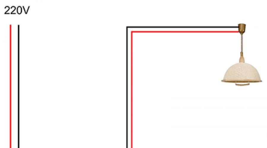
Let's consider typical installation single-key switch. Two wires are supplied to the lamp socket: zero and phase. Let's say you open the neutral wire using a switch. The light will go out, but there will always be a dangerous potential of 220 volts on one of the cartridge contacts. If you touch this contact while replacing the lamp, you will receive an electric shock. And this is with the device turned off!
Therefore, the neutral wire always goes directly to the light source, and the phase wire passes through the switch contacts.
In this regard, there is a positive " by-effect» when choosing a circuit breaker installation scheme with the “zero” and “phase” inserted into the housing. Thanks to the “high competence” of electricians, it is possible to change the neutral and phase input to your home. You can change the so-called "polarity" on the input without changing the entire wiring configuration.
Ground switch
Despite the apparent absurdity, there are such models. In general, the grounding loop should not have disconnecting devices along its entire length. Therefore, the switch contacts with grounding do not intersect. Metal parts of the housing may be grounded: for example, the mounting substrate is often made of steel for strength. When installing internal switches in the bathroom (which is generally undesirable), or in places where the housing could potentially get wet, protective grounding is used. If a dangerous potential of 220 volts occurs on the housing and a wet wall, a short circuit or current leakage will occur. The circuit breaker or RCD will trip.
Geometry of switching devices in the room
There are no strict rules for violation of which there are sanctions. You can place them as you see fit. For example, instead of installing two-gang switch, it is permissible to place two single-keyboard players side by side. However, there are accepted in the European Union and Russian Federation standards, the implementation of which is recommended for your own safety.

Do I need backlit switches?

This is a convenient feature; you won’t have to fumble the keys in the dark. However, there is also side effects. Regardless of how the backlight is implemented (LED with a resistor or neon lamp), a small galvanic connection occurs between the phase and neutral wires. This does not affect safety, but some types of lamps may glow slightly when off.
Connecting two or three-key switches
If you do not have a lighting brightness adjustment system, it makes sense to connect a multi-arm chandelier combined method. For example, a two-key switch allows you to select 3 lighting levels (on a lamp with 6 lamps):
- first key - 2 lamps
- second key - 4 lamps
- both keys - 6 lamps

The connection diagram does not depend on the method of installation of the switch (see section " General principles installation of switches"). A phase wire is supplied to the common contact, and the necessary groups of consumers are connected to the output contacts (2 lamps or 4 lamps on a chandelier).
When connected various sources light, the connection principle is the same, with the exception of the combined neutral wire. It must be separated into both light spots.
For example, using one three-key unit, you can turn on a chandelier with three levels of brightness (see description above) and a night light. In practice, switches with no more than two keys in one housing are usually used. The only exception is in the case of total space saving.
Proximity switches
For ease of use, switching devices are produced without mechanical keys. For example:
- sensory ones are triggered by a raised hand;

- acoustic ones turn on (turn off) the light by clap or voice command;
- switches with motion (presence) sensors also operate without mechanical contact.
There are also automatic switches that are triggered by a timer, or when an external command is given (phone call, SMS, or control using a computer application). True, the installation of circuit breakers must provide for the possibility of forced unlocking. In case the electronics fail.
Installation touch switch, as well as any other with a control circuit, from the point of view of electrical installation work is no different from ordinary “mechanics”. Power contacts are connected according to the same principle. Unless the “remote switch” circuit from the distribution box may not work.
But the control scheme may require a qualified approach. At a minimum, the control unit requires a separate power supply. This can be a built-in module in the housing, or a remote device that needs to be discreetly mounted nearby.
Automatic switches for lighting systems
Although the installation circuit breaker It is practically not used to power light points; to save equipment, such a connection is acceptable. In this case, a separate group of “automata” is allocated on the power panel, to which the lighting network is directly connected. Connection is made via standard scheme: contacts open phase.

Otherwise, when you turn off the light, you may mistakenly turn off the power important node. If possible, such switches are placed in a separate panel.
The advantage of this method: the machines are designed for higher loads and immediately include protection functions. The reliability of such devices is higher in comparison with household switches. The disadvantage is that when used in a residential area, such a switch does not look aesthetically pleasing.
Bottom line
As can be seen from the description, installing home switches is not difficult. In comparison, installation of a vacuum circuit breaker in production requires sophisticated equipment and qualified personnel. Special alloys and high-strength bolt ties are used.

A contact groups household electrical appliances are designed for direct connection of wires, without the use of special terminals.
Video on the topic
Connecting a single-key light switch is a task that sometimes faces a home electrician. Majority lighting fixtures controlled by exactly these switches. This article discusses in detail the sequence of actions for connecting a single-key switch and installing it at home without outside help.
Preparatory work before installing the switch
To connect the light switch, preliminary preparations must be made. Installation is carried out from the nearest distribution box to which power is supplied - network cables supply of electric current.

Power to the switch and lamps is supplied from the distribution box
Three lines are laid - one from the junction box to the lamp, the other from it to the switch. The third one comes from the shield. As a rule, two- or three-core wires of the installation type are used, i.e., with a copper (or aluminum) conductor made of solid metal. In everyday life, such a wire is called hard, in contrast to soft, in which under the insulation there are pigtails of small hair conductors. On the marking, a rigid cable is designated by the letter “U”. The cross-sectional area of the conductor is selected in accordance with the load. For an ordinary lamp or chandelier, which combines up to 3 lamps, a wire with a cross-sectional area of 1.5 mm 2 is sufficient.
If energy-saving or LED light bulbs are used, the cross-section of the conductor can be reduced to 0.75 mm 2 in order to save money.
The type of wiring installation can be of two types - internal (hidden) and external. Hidden wiring installed in the thickness of the wall or ceiling. The outer one runs along their surface, the cable is packaged in a corrugation or cable channel, which is attached to the wall with special brackets or other fastening material.
After the wires are separated, you can begin installing the switch.
Single-key switch connection diagram
The principle of operation of the switch is based on breaking the power supply circuit of a light bulb or any other device. Switching the toggle switch activates a contact pair, which disconnects power wire from the current consumer.

The switch usually opens the phase wire
When assembling the circuit, you should pay attention to the reliability of the contacts. If the wires have large gaps, then in one wonderful moment so-called electric arc, the temperature of which is sufficient to melt and ignite the insulation. This can lead to smoke in the living space and even a fire. In order to avoid such phenomena, the following connection methods are used:
Twisting of copper and aluminum wires is also possible. But if the connection is overloaded, aluminum may melt, since it has more low temperature melting than copper. The contact will be interrupted.
Tools and materials for connection
To connect you will need the following tools:
- Electrical screwdriver.
- Household voltage indicator.
- Pliers.
The materials on hand should be:
- Wires of the required length.
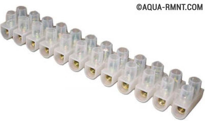
- Terminal blocks or electrical tape.
- Lamp socket (and the lamp itself).
Pay attention to our article, which describes in detail how to choose the right switches:.
Photo gallery: materials for switch installation
The cable length is pre-measured with a tape measure at the work site  Depending on the type of wiring, you need to use external or built-in (internal) distribution boxes
 The cartridge is attached to the ceiling with self-tapping screws
  The base of the “correct” switch can be ceramic or high-quality plastic
Step-by-step instructions for connecting a single-key switch
If all the tools and materials are ready, you can begin assembly. The procedure can be divided into two steps:
- connecting switch contacts and light bulbs;
- switching cables inside the junction box.
Before this, all wires are fixed in their designated places in cable ducts or corrugation. The distribution box and socket for the switch are firmly installed in (or on) the wall. The procedure has no of great importance, but experienced electricians always start connecting from the periphery - a switch and a light bulb, and finish by connecting the wires in the box.
Connecting the switch and lamp

Exist various models switches, but for the most part they are secured in the socket box using a spacer mechanism mounted on the base. Before attaching the base, you need to connect the wires to it. To do this, the screws of the clamps are loosened, the wires are inserted into the sockets, and the screws are clamped again. It is important not to overtighten the threaded fastener - you need to tighten it so as not to damage the screw slots.
If there is no socket box and the switch is attached externally, screw the base to the wall surface with two screws.

The external switch is installed directly on the wall surface
At this stage it needs to be positioned correctly. It is customary to install the switch so that turning it off is done by pressing the button down, and turning it on is done up. This is done for security reasons. If something accidentally falls on the switch from above, the mechanism will break the circuit and turn it off.
After screwing the screws into the wall and securing the base, the installation of the switch can be considered complete. All that remains is to insert the key into place, but this can be done at the very end, after checking the operation of the entire circuit.
Connecting cables in a junction box
Before connecting the conductors, it is necessary to de-energize the supply line electricity into the junction box. To do this, you need to turn off the plugs or the automatic breaker on the meter panel.
It is very convenient to carry out switching according to the color of the cores. Using a voltage indicator, you need to determine which core contains the phase and which contains the zero. Touching the phase wire will cause the diode on the probe to glow.

The indicator is activated by placing your finger on the red cap
Typically, the “phase” is connected to the red wire of the wire, “zero” to the blue, and “ground” to the white.

If the wiring in the house is made with three-core cables, all the white ground conductors are connected to each other.
Video: connection diagram for a single-key switch
You may also find the connection instructions helpful. pass-through switch: .
How to connect 3 sockets and 1 switch from one junction box
Sometimes you need to connect one or more additional sockets to the existing wiring. This can easily be done by running another cable into the junction box.
It should be noted that for sockets it is customary to use connecting wires with larger area sections. This is due to the fact that a variety of different Appliances. This could be a kettle or, for example, a vacuum cleaner. Their power consumption is higher than that of a simple light bulb, and therefore the thin wires can heat up, which is undesirable. Therefore, sockets are connected with cables whose cross-section starts from 2.5 mm 2.
The connection process consists of connecting the wire to the power line that comes to the distribution box from the switchboard. As with the installation of the switch, all work should be carried out only with the plugs turned off.

When connecting wires using twists, it is advisable to thoroughly clean all contacts with a knife or fine file. Sometimes old wiring oxidizes at the joints and the contact becomes unstable. When adding new wires, twisting is done using pliers.
To avoid short circuit the insulation must completely exclude possible contacts of wires with different poles.
Video: connecting a single-key switch and socket
How to connect a one-key switch to two light bulbs
If you need to turn on two light bulbs at the same time from one switch, located in different places, the same connection diagram applies.
The current supply to the lamps is controlled by a single switch, but the connection options for the lamps themselves may vary.
New cable in box
Another cable is inserted into the junction box. The ends of the conductors are stripped and connected to the same terminals as the first lamp. This will take up some additional space inside the box, but if there is enough space, then nothing bad will happen.

One way to connect two light bulbs to one switch is to connect both pairs of wires to the same terminals
Cable from an existing device
A tap is mounted from an existing lamp, which is connected to it in parallel. To do this, two additional contacts (“zero” and “phase”, red and blue) are inserted into the socket of the first lamp and extended to the second lamp.

Advantage parallel circuit connection of lamps is the possibility of using them in any quantity
The choice of connection is selected depending on the situation. The second option is used more often, since there is often not enough space in the distribution box to insert additional cables. In addition, in this way you can connect not only two lamps, but also a larger number of them. The main thing is to follow the principle parallel connection wires
Do you want the lamps to turn on smoothly? See connection diagrams for such a system in our next material: .
When installing household electrical equipment, you need to remember to comply with safety standards. Before starting work, be sure to turn off the power supply. It is better to use tools with dielectric coating and cables of the appropriate cross-section. Do not throw bare ends of conductors onto radiators or water pipes. In addition, the standard connection parameters must be observed.
Any comfortable housing is unthinkable without communications and electrical wiring. In case of some problems in the operation of various household appliances and equipment, you can fix them yourself, without necessarily resorting to the help of specialists. In this article we will look at how to properly embed switches and sockets into the walls of your house - what place to choose for this, what tools will be needed and what is the sequence of work.
Operating principle of the switch
In our modern world It's hard to imagine a room without a switch. It is often a small plastic box with a metal filling and one or two keys that act as a connector or disconnector in an electrical circuit. In the on position, they connect the power line from the switchboard to the chandelier, and in the off position, they break the circuit, stopping the flow of current through the wires. 
The operating principles of switches are quite simple. To light a light bulb, two cables called phase and neutral are connected to its base. Only the phase flows from the distribution box towards the switch. Here it is branched into two cables, one of which is laid from the box to the switch installation point, and the second is routed from the switch to the lamp itself. Thanks to the key switch, phase cables are coupled and uncoupled.
Did you know? The first evidence of people receiving electric shocks was found in ancient Egyptian texts dating back to 2750 BC. It's all because of the fish, in particular the electric catfish, capable of delivering current pulses of up to 360 Volts.

Selecting a location
In the recent past, there was a tendency to install switches at eye level so that people could see where to turn on and off. Today, they mainly use the hand level rule for greater convenience when changing the position of the keys. They also try to hide switches as much as possible from view, as well as sockets, so as not to spoil appearance walls
Generally special requirements to the location of the switch, its position relative to windows, doors, floor and ceiling there is no. The main thing is that you feel comfortable and comfortable using it.
In accordance with modern trends in design and landscaping, it is customary to place the switch at a height of about a meter from the floor and close to the doors, so that you can turn on the light immediately upon entering the room.
If we talk about sockets, then they need to be placed at the same level relative to the floor and walls, but at different walls. The best option make one socket on each wall or place them as required by the number and location of future electrical equipment. 
Necessary tools and preparatory work
Before you start drilling the walls and drilling out a place for the switch, you need to take an inventory of the tools at hand so that unexpected troubles do not occur during the work, such as the fact that you have a drill, but there is no special attachment for drilling round holes in the wall. So, your arsenal of tools should include:
- perforator with a drill with a diameter of 6 mm;
- dowels;
- punched paper tape;
- nails size 6x40;
- PVC pipe (corrugated or regular);
- cable of the required section;
- attachment for a hammer drill or drill for drilling round holes;
- switches according to the required number;
- sockets according to the required number;
- level (regular or laser) for marking wiring, sockets and switches.

After you have prepared all the necessary tools and checked their configuration and functionality, you should make sure which of the incoming wires supplies voltage and which does not.
Important!After identifying a live cable using a special device, it is necessary to de-energize the apartment by turning off the toggle switches in the switchboard. Don't neglect it important rule to avoid irreparable consequences and injuries.
Cable laying can only begin after all preparatory work has been completed, including one of the main stages of preparation work surface.To select the correct cable thickness, you can follow the following rule: 1 square millimeter cable withstands maximum voltage at 1.5 kW.
You should drill carefully, slowly, stopping periodically and checking whether the direction has gone astray. It is also worth breaking the planned work into parts to give the hammer time to cool down, as well as for you to take a break. 
Preparing the work surface
Before laying the cable, you need to carry out marking work and use a level to determine where the grooves for the cables will be located, as well as mark the location of sockets and switches. Only after this can you begin to clean the working surface down to the concrete. It is necessary to remove plaster, wallpaper and others decorative materials from the walls before starting the hammer drill. Since you will be spraying anyway, there is no need to treat the walls with a layer of primer mixture. Now you can proceed to preparing the wiring itself for further installation and installation.
Preparing the wiring
For correct and maximally protected installation of the cable in the grooves, you need to prepare special protective PVC pipes (corrugated or regular). They will act as protectors of the cable surface from sharp corners grooves, and especially at kinks, where the danger of chafing and damage to a thin cable is most significant. 
Thread the cable into the prepared PVC pipe, and then lay them in the groove.
In order to strengthen the tube with cable in the wall, you need to prepare special holes at a distance of approximately 30 centimeters from each other. Drive special dowel nails into these holes onto which you secure the punched tape. This tape will hold the tube in place, preventing it from moving. Simply wrap a corrugated or regular PVC pipe with a cable in punched tape and repeat the same operation along the entire perimeter of the wiring.
Also at this stage you need to install special socket boxes. To do this, select a wall using a round attachment on a hammer drill, then lay the cables into the corresponding holes in the plastic socket box, and then secure the socket box in the recess using screws.
Adapter terminals are installed in cases where it is necessary to make a high-quality connection of two or more cables. In order to install the adapter terminal, you need to first strip the cable from the braid. Suitable for this regular knife or clerical. Carefully strip the braid at the end of the wire about 1-2 centimeters. Next, insert the wires needed for connection on both sides, and then clamp the ends using a bolt. 
How to connect wires
After the wiring has been done, you need to move on to the next stage of installing electrical equipment, which consists of connecting it to the electrical wires coming to your home.
In order to achieve maximum installation results, you should use your imagination and imagine that the wires have become “pipes” and the electric current has turned into “water”. “Water supply” occurs along the phase cable line, while “return” returns through the neutral cable, and protective conductor created for a foreseen emergency scenario, for example, if a leak is detected in some place, the “water” will certainly be “drained” into the ground.
Thanks to technical progress today the wires are painted different colors, which is very convenient for a beginner in electrical wiring. 
Did you know?One of the most common colors has the following color range: White color– phase (L), blue – zero (N), yellow-green – ground (PE).
Producing electric installation work, you need to clearly follow and maintain the sequence of cable colors in order to significantly facilitate your task of installing them in the junction box. For ease of further use, preventive and repair work It is recommended to mark in advance those points where such distribution boxes will be installed, where wires from all lighting points, sockets and switches will be collected. 
And now, finally, you have reached the point of installing the switch mechanism. Basically, the following step-by-step scheme is used in assembling and installing the switch:
1.De-energize the phase, then remove the keys from the subframe. Below them are two mounting screws, which are the connectors of the front part of the switch with their electronic mechanism. Unscrew both screws and disconnect the subframe and the working element of the device.
2. Now you have to disassemble the screw mount, which serves as a clamp for the wires inside the mechanism.
3. Strip the braid on the wires, leaving about 1-2 centimeters of each cable clean.
4. Insert the wires into the mount so that its exposed fragment barely protrudes beyond the structure (approximately 1 mm).
5. Tighten the screws that secure the contacts tightly. Next, tug the wires a little to check the strength of the fastening. It is important here that the ends of the wires cannot move freely. But you also shouldn’t overtighten the fasteners, because you can break the threads or crumble the fragile plastic.
6. Insert the switch mechanism into the socket box pre-fixed in its place, guided by a strict horizontal position.
7. Using special spacer brackets, secure the working element of the switch by screwing in the screw fasteners that regulate them. Check the reliability of the built-in switch.
8. Now place a protective subframe on the structure and secure it using special screw clamps.
9. Position the keys and check their functionality. 
This completes the installation of the switch. You can turn on the electricity and test its functions in practice.
Important!On the back of the functional mechanism on the switches, the places of incoming and outgoing contacts are marked with certain symbols. For example, the input can be designated by the number 1 or the letter L of the Latin alphabet, the outlet cable socket is marked by the numbers 3, 1 (if the input is marked L) or an arrow.
Fixing the pad
The cover is fixed using special screw fasteners or simply pressed against the wall by the switch subframe. As a rule, the second type of lining is more common. But such a device was popular in Soviet times and is rarely used in the modern world. 
Features of installing double switches
A device with double keys is used in large rooms where there is a massive chandelier with a large number of light bulbs or simply a lot of lamps. This type of switch is also used in separate bathrooms, when one button turns the light on and off in the bathroom, and the other performs the same operations in the toilet.
There are no particular differences between single-key and double-key switches. The main difference is that three phase cables come to the two-key switch: an input cable and two output cables. In this case, only the input is energized. 
Did you know? Lightning is one of nature's most powerful suppliers of electricity. Our distant ancestors believed that lightning striking a specific area was an indication of the source of water and that it was better to dig a well in this place.
Sometimes it is difficult to immediately understand which groove one or another wire should be inserted into. But when it comes to practice, this complexity is not such at all. The main landmark in correct installation This switch is a screw located on the front side of the mechanism. It is under this that you need to place the cable that is phase and will supply electricity. The two lower slots were provided for two de-energized phases. Have more modern devices, which are an order of magnitude higher in quality and, accordingly, price, the following designations were placed on the back of the switch by the manufacturers:
- when we are talking only about digital symbols, then 1 is the supply wire, and 2 and 3 are the outlet wires;
- if the mechanism has the icons L, 1 and 2 or L and two arrows, then the supply wire is connected to L, and the outgoing wires are connected to the rest.
 Otherwise, this version of the switch is largely identical and is no different in assembly and installation from a single-key device. Write in the comments what questions you have not received an answer to, we will definitely respond!
 In this article we will look at the issue in detail. There's no need to rack your brains
Who to contact with this problem, where to find an electrician. There is no need to waste time searching and spending money on calls; all this is done easily and simply. You just need to follow the detailed instructions given in this article and question how to install a light switch, will be solved without any difficulties or puzzles.
So, we have a new one-key switch and a desire to install it.
The installation site still looks a little sad, an empty socket box and two wires sticking out of it, but this is only until we installed new switch.
Preparing the circuit breaker for installation
First of all, before carrying out all work, it is necessary to determine the wire with the incoming phase using a voltage indicator (pointer). To do this, we alternately bring it first to one wire, then to the other. Mark the one you need using insulating tape.

Now, we turn off the electricity, check that it is not on the wires, use it, and only after that we get to work.
There are a huge variety of switch types. They differ: by manufacturer, by price category, quality of execution, various methods connecting wires to contact terminals and so on.
Let's consider two main installation options. In the first case, we will install a switch in a cheap price category of up to 80 rubles.
We prepare the switch for installation, and at the same time we will find out how the switch works.

Using a flat-head screwdriver, remove the switch key, slide it on the left or right side and disconnect it from the body.

We unscrew the two screws located diagonally on the protective frame and disconnect it from the mechanism.


There are four screws on the mechanism, two of the bottom ones are contact screws, they are designed to connect wires to the mechanism. The other two drive the spacer mechanism, which is designed to securely fix the mechanism in the socket box.

Contact screws.


Left and right spacer screws.


We unscrew the contact screws; on the upper end side you will see how the pressure plates move.

One of the contacts is incoming, the phase comes to it, the other is outgoing, the phase goes from it to the lamp. Each contact has two holes for connecting wires. We figured out how the switch works, let's move on to the next stage.
Switch connection
We strip the wires and remove required amount insulation, approximately 1 cm.

On inexpensive single-key switches, as a rule, the designation of the contacts, incoming and outgoing, is not indicated, but just in case, look at back wall mechanism, designations can be as follows:
- numbers 1 and 3 - here there is 1 contact of the incoming phase, 3 of the outgoing phase
- letter L and number 1 - here L is the contact of the incoming phase, 1 of the outgoing phase
- letter L and arrow - here L is the contact of the incoming phase, the arrow is the outgoing phase
This is the most common designation.
Let's return to our switch. We insert the stripped wire into the hole, make sure that it is between the pressure plates, and tighten the contact screw. We check how well the wire is fixed. It should not swing or wobble; if this occurs, tighten the contact screw. A poorly drawn contact will burn out and subsequently lead to failure of the switch.
Don’t overdo it; on inexpensive switches, the screws and threads are not very reliable and are very easy to break.

The bare core of the wire should protrude 1-2 mm from the contact.

Insert and tighten the second wire.

Unscrew the screws of the spacer mechanism, insert the switch into the socket box, align it horizontally and fix it. We tighten the spacer screws and check the reliability of the mechanism in the socket box.

We install the protective frame, tighten the diagonal screws, securing it to the mechanism.

Set the key. Before installation, we look at the alignment of the pins and grooves of the moving part of the mechanism and the key.

This completes the connection of the switch.

Let's now consider the second installation option.
How to connect a light switch, option two
This option includes switches with an expensive price category of over 100 rubles apiece.
We prepare the switch for installation. During the process, we look at its device.
These switches are generally not sold in complete set. The mechanism and key are together, but the frame is separate. This is done to be able to apply creativity in the design of the switch, for example, a white key, a black frame, and so on, at your discretion.
The switch key can be removed very easily by hand. We're filming.

Screws for spacer feet are located on the left and right.


Turn over the switch. The first thing that catches your eye is the complete absence of screw terminals and clamps. This category of switches has plug-in contacts, which have proven themselves quite well in lighting.

Let's take a closer look. Switches of this class always have symbols.
IN in this case:
- L - contact for incoming phase wire
- down arrow - outgoing wire contact
Each contact has two contact plug holes.

We strip the wires and remove 1 cm of insulation.


We insert the wires one at a time into the contact.

The wire should fit tightly and rest. In this case, it is allowed for the wire insulation to stick out from the contact by 2-3 mm. We check how the contact is clamped, try to pull the wire back, if with a certain force (not with all the force) it does not pull out, the contact is good. We continue connecting the switch.

Let's move on to the next wire.

If it becomes necessary to pull the wire out of the plug-in clamp and adjust the length of the stripped core, press the lever specially provided for this purpose.

We press and the wire is free again.

After connecting the wires, we proceed to installing the mechanism in the socket box.

If your mechanism is installed into the existing socket box without any difficulties and is securely fixed there, then all you have to do is put on the frame and install the key. But as a rule, in most cases the mechanism is not fixed in the socket box, the spacer legs do not reach the edges of the socket box, it is too large. TO How to connect the light switch if such a situation arises? Let's figure it out.The fact is that before there were other standards and the switch mechanisms were more massive. Now switches have become more compact, the mechanisms no longer take up so much space in the socket box, and the installation of the switch in the socket box itself has undergone some changes.For new, modern switches, corresponding socket boxes are made.

They are now made not from iron, as before, but from special non-flammable plastic.
When purchasing a new switch, you must definitely purchase a socket box for it, they mostly have standard diameter 67 mm.
So, in this article, we examined in detail two connections of a switch with one key, having analyzed two different examples installations, and now we can rightfully consider this topic closed.
To carry out work on installing the switch, we used:
Material
- single-key switch - 1 pc.
- socket box - 1 pc. (needed in some cases)
- gypsum or alabaster - 200 grams (required in some cases)
Tool
- voltage indicator
- pliers
- wire cutters
- Phillips screwdriver
- flat screwdriver
By installing the switch ourselves, we saved:
- - 200 rubles
- dismantling the old socket box - 100 rubles
- installation of a socket box indoor installation(brick wall, hole drilling, installation) - 200 rubles
- installation of a single-key indoor switch - 150 rubles
TOTAL: 650 rubles
Previously, the light in the room was lit by simply turning the incandescent light bulb in the socket. This is not only inconvenient, but also unacceptable for modern lighting devices. Now important element lighting system is a switch. This simple device can be installed independently. Our article describes how to do this.
In their most common form, switches are a small button that can be pressed to close or open electrical circuit room lighting.
The installation location of the switch can be different, it all depends on the user’s preferences. Previously, the coveted button was installed at the eye level of a person of average height. Now the switch is mounted so that to bring it into working condition there was no need to raise your hand.
The principle of operation of the switch is simple. In order for a light bulb to light, two wires are connected to it, which are called phase and zero. Only the phase is supplied from the distribution box to the switch. Here it breaks into two wires: one goes from the box to the installation location of the switch, and the other from the switch to the lamp. Connection and disconnection of phase wires is carried out using a key.
Types of switches
Structurally, all switches that are currently offered on the electrical goods market are divided into single-key and two-key. In addition, they may differ depending on the connection type:
- closed ones are used where the wiring runs in the wall and a place has been prepared for mounting the switch;
- outdoor switches are connected to outside wiring, which is much less common today.
Let's start with a description of the design and method of connecting closed switches.
Installation of a closed type switch
At the location where the closed switch is mounted there should be a cylindrical recess in the wall, usually equipped with a socket box, which is a metal or plastic cup through the bottom of which a wire for connection comes out. It is convenient that the length of the wires for connecting the switch is 10 cm.
How to install an enclosed one-gang switch

Whatever the switch, before proceeding with its installation, it is important to use a voltage indicator to determine which of the wires is live and which is not. After this, it is necessary to turn off the power supply to the installation site of the device and again check the presence of current on both wires.
Single-button switches may differ slightly from each other depending on the manufacturer and price.
Most simple design have devices whose price does not exceed 80 rubles. The mechanism of such a switch has expansion brackets for installation, which are tightened with screws. To connect each of the phase wires there is also a screw to which holes lead. The entire installation includes the following steps.

Step 1. After the phase is completely de-energized, they begin preparing the switch itself for installation. To do this, remove the button from the frame. Under the key there are two screws connecting the mechanism to the face of the switch. They are unscrewed, disconnecting the frame from the working element of the switch.
Step 2. Unscrew the screws to connect and secure the wires.
Step 3. Strip the insulation from the cables, leaving about an inch of each wire exposed.
Step 4. The phase cables are inserted into the holes going to each screw so that the bare section of the wire does not fit into the groove by 1 mm of its length.
Note! Even on some cheap switches, the places of the input and output contacts are marked with symbols on the back of the operating mechanism. The input can be marked with the number 1 or the Latin letter L, the outlet cable socket is marked with the numbers 3, 1 (if the input is marked L) or with an arrow.
Step 5. Tighten the screws that secure the contacts and check how firmly the connection is made. The ends of the cables must not move freely.
Note! The screws on cheap switches, as well as the threads for them, are not particularly strong, so do not overtighten the fasteners.
Step 6. Now the mechanism is installed strictly horizontally in the socket box.
Step 7. Fix the working element with spacer brackets, tightening the screws that adjust the spacers. Check whether the switch is securely installed.
Step 8. Place a protective frame on the mechanism and secure it through special holes with screws.

Step 9. Install the keys.
The installation of the switch is completed.
Single-key devices, the price of which is above 90 rubles, differ slightly in their design and installation process. At the very beginning, do not forget to check the active phase and turn off the power supply.
Note! For more expensive switches, the frame is sold separately, and the device itself consists of a mechanism and a key attached to it.

Step 1. Before proceeding directly to installing the switch, install a special plastic socket box. It is mounted into a concrete wall using alabaster.

The socket box has a special hole for the wire.

Step 2. Remove the key from the mechanism.
Step 3. The holes for the wires on such a switch do not have screws, but are designed so that the contacts are securely fixed in them. To do this, the wires are inserted into the slots in accordance with the indicators: L – inlet, down arrow – exit.
After the bare contacts are inserted tightly into the holes, it is necessary to check the strength of the connection. To do this, pull the wires lightly. If for some reason you need to pull out the cables, then press a special lever located on the side of the mechanism.
Step 4. Mount the mechanism in the socket strictly horizontally and fix it with screws.
Step 5. Install and fix the frame using a special latch.
Step 6. Secure the key.
The switch is ready for use.
Two-key switches and their installation


Such a device is installed to control chandeliers with big amount light bulbs or, for example, for a separate bathroom. The design and installation principle of a two-button switch is not very different from a one-button switch.
The difference is that 3 phase wires are connected to the switch: one is input, the other two are output. Only the first cable is live.
Cheap switches do not have markings on which wire to insert into which slot. In fact, it’s difficult to get confused here. There is one screw on top, so the wire supplying current is connected here. The lower slots are provided for the de-energized phase.
More modern and expensive devices On the back of the switch there are the following symbols:
- when we are talking only about digital symbols, then 1 is the supply wire, and 2 and 3 are the outlet wires;
- if the mechanism has the icons L, 1 and 2 or L and two arrows, then the supply wire is connected to L, and the outgoing wires are connected to the rest.
Note! If you do the wiring yourself, then it is better to make all 3 wires of different colors.
Otherwise, the installation is no different from single-button switches.
How other types of switches are mounted

External devices are even easier to install. They do not need socket boxes, but it will be necessary to drill holes at the installation site for dowels.
Switches with backlighting on the keys are a little more complicated, but this does not affect the installation process. And devices that respond to voice, clap or other signals are supplied with detailed installation instructions.
Video - Installing a switch yourself. Connecting a single-key switch
Video - Connection diagram for a two-button switch