Volumetric optical-electronic photon detector 9. Warning system. How to make a warning system with your own hands
Read also
We live in society, work at work, study and spend time with family. Our life is limited by rules. In addition to laws, there are also private rules, for example, behavior at work, school, and even rules of behavior in the family established by elders. These rules are not always reasonable and necessary, but violating them is fraught with trouble. We will design a warning system that will alert you to the approach of the person who sets or controls the rules. And forewarned means forearmed. The TV and computer can be turned off in time, unwanted activities (games, hugs...) stopped. And if you live in a separate house, then you can prepare to repel the entry of an unwanted guest into the yard - a bear, wild boar or elk;). The invention is simple, assembled from ready-made blocks and the cost will be less than 1000 rubles.
How to make a warning system with your own hands
Electrical goods stores offer big choice motion sensors for organization automatic lighting. In the same stores you can also purchase a radio call. A motion sensor (manufactured by IEK) controls the switching on lighting fixture depending on the lighting and the location of the thermal object in the control zone. The radio call is a self-powered radio button, a signal encryption unit and a microtransmitter at a frequency of 433 MHz powered by a 12 Volt battery. Receiving unit also operates autonomously on AA or AAA batteries. The unit's receiver picks up the signal from the button at a distance of up to 100 meters. Depending on the brand of radio call, you can select several melodies. The volumetric sensor was closed - the photo sensor was closed and the light control contact was installed separately and galvanically isolated from the network. The relay contact was supposed to control the radio bell button. But such a system did not work during testing. When the button was turned on, interference occurred in the sensor block, even when the button was placed at a distance of 1 meter, and the relay did not turn off. Perhaps sensors from other companies will work more reliably.
Button extension conductors Bad option
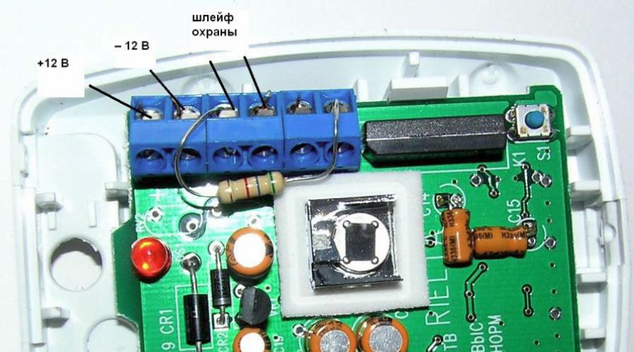
A way out of the situation was found by using a volumetric sensor from alarm and security systems of the Foton-9 type. These sensors are powered constant voltage 12 Volt, which is very convenient. But there are some peculiarities here too. The Photon-9 sensor generates an alarm by opening the control circuit; on the contrary, we need to close the circuit for notification. Of course, this problem can also be solved, for example, by installing a two-position relay or adjusting the relay control circuit. The issue was resolved even more simply. Some computer blocks food and everything impulse blocks laptop power supply circuit feedback have optocouplers in the circuit. Having obtained such an optocoupler, the issue of finalizing Photon-9 was resolved in 10 minutes. The sensor has an LED that turns on when there is an alarm. So, an optocoupler is connected to the LED power circuit through a current-limiting resistor of 150-240 Ohms. The counterpart of the optocoupler is connected to the control terminals. The relay contact is disconnected by unsoldering the limiting resistor, this is the only serious intervention in the electronics of the device;). Look at the photo.
When installing an optocoupler, you should not forget about the correct connection of both the receiving and control parts. See the diagram. The connection to the radio button is determined empirically. The issue of powering the circuit is resolved by using finished block power to charge an unknown gadget. On the body of the unit it was written 12 volts, in fact output voltage without load it was 19 volts. Since the load is low-current, for safety, a 7809 microcircuit was installed in the unit, which provided the necessary voltage to power Photon-9 and the radio button. Tests assembled circuit showed that the experiment was a success. The scheme worked!
The power supply has been improvedThe book contains practical recommendations on the main types of plumbing, construction and electrical work that most men have to deal with in an apartment or own home. Considered replacement of radiators and hot/cold water taps, repair and installation of faucets, replacement of pipes, connection of washing and dishwashers. The creation of apartment partitions, the installation of double-glazed windows, the glazing of a loggia, etc. are described. It is shown how to lay apartment electrical wiring and carry out installation electrical switches, sockets, lamps and chandeliers, ground household appliances and etc.
Book:
| <<< Назад
|
Forward >>> |
Pyroelectric motion sensors(hereinafter referred to as DD) have been used in everyday life for ten years and are integral part security, automation and warning systems. No one " smart House“Today we cannot do without these inexpensive and accessible sensors.
The sensors are freely available in electrical supply stores. Among the many DDs, a distinction is made between complete automatic units and local sensors.
The first of them, intended for domestic needs, are equipped with their own transformerless power supply and a load control unit in a 220 V network, allowing switching current up to 6 A.
Another feature is the presence of adjustable photosensitive relays and a timer responsible for delaying load shutdown. Some household DDs have a housing combined with a powerful lighting lantern, inside of which a halogen lamp (rated for 220 V) is installed. These sensors are used in everyday life and for personal purposes.
Local DD are the most specific. They are designed for devices security alarms and security, warning and presence indication. Initially, the DD data were calculated for collaboration in systems with centralized power supply and backup sources uninterruptible power supply(IPB) – in multifunctional control systems for a security complex, coded access, indication and remote control. These DDs are (separately) two orders of magnitude cheaper than their everyday “brothers” and can be adapted for the needs of a radio amateur using the author’s recommendations given below.
So, the first thing you will have to deal with when adapting a “security” DD in everyday life is a separate power source with a constant output voltage.
Attention, important! Any stabilized power source with an output voltage of 9-15 V will do. If a connecting cable of more than 2 m is needed from the power source to the sensor, I recommend installing an oxide capacitor with a capacity of 1000-10000 μF at the point where the cable is connected to the sensor (in the latter’s housing) parallel to the power circuit operating voltage of at least 25 V - to smooth out voltage ripples and, as a result, to localize power supply interference.
Security motion sensors have the same principle of operation and differ in some additional functions, for example, trigger indication and sensitivity adjustment. In Fig. 3.58 presented DD IO315-1 "Orlan" for digital encoded security complex type "Signal-201" and similar.
Rice. 3.58. Appearance sensor IO315-1 "Orlan"
The sensor is manufactured by Rielta. The sensor is labeled as a “security detector”.
The sensor is equipped with a three-level LED response indicator and sensitivity adjustment of the scanning area. If we remove the top cover of the Orlan case, we will see a printed circuit board with elements (Fig. 3.59).
The sensor has a self-protection function - for this purpose there is a button SA2, the contacts of which are closed when the housing cover is normally closed. Switch SA1 is responsible for the sensitivity of the sensor and the combination of output signals when the security loop is triggered. The connection is made to the terminal block on the sensor board.

Rice. 3.59. View of the printed circuit board of the IO315-1 “Orlan” sensor
Attention, important! Despite the fact that this DD (like all those discussed in this book) is structurally designed to work as part of a multifunctional security complex, it can also be used separately (as part of a corresponding amateur radio design).
To do this, the power is connected to the “–” and “+” 12 V terminals. The security loop is connected to the ShS2 contacts. In this case, this loop has a normally open state (i.e., there is a large resistance between the ShS2 contacts) - if no power is supplied to the sensor and if (with the power connected) movements (movements) occur in the sensor’s area of responsibility. If the power is connected and there are no movements in the sensor area, the state of ShS2 is closed contacts.
LEDs HL1-HL3 (yellow, red, green) light up as the sensor is triggered to move in the control zone. The most sensitive is the “yellow” zone (then “red” and “green”). For example, in practice, the yellow LED flashes randomly when someone approaches the sensor. Red lights up (or flashes when a person approaches closely, green when there is active movement directly in front of the sensor).
LEDs can light up simultaneously (in particular, this happens when the DD is connected to power). The contacts of the ShS2 security loop change their state with any reaction of the sensor to movements (lighting of an LED of any color).
Thanks to LEDs with DD it is convenient to conduct experiments, control their operation and adjust sensitivity.
The sensitivity of this DD is adjusted by moving the jumper to printed circuit board(there may be high and normal sensitivity).
The jumpers on switch SA1 should be in position 1–4 - “on”, 5 - “off”.
Thus, to control the alarm device using the sensor considered, you need to connect power to it and wires to the ShS2 loop. The counterpart of the ShS2 wires is connected to the input of a digital device that receives high or low logic level signals.
For example, ShS2 contacts are connected between the common wire and the control input of a logical CMOS chip. A constant resistor with a resistance of 91 kOhm is connected between the control input of the logical CMOS chip and the “+” power supply (the resistance is indicated approximately and may differ by 20%). Thus, until the DD is triggered, the input of the microcircuit will be shunted by the ShS2 contacts to the common wire. In case of violation of the DD control zone, the ShS2 contacts open, a high logical level signal appears at the control input, which leads to the activation of the alarm. When the sensor’s power is turned off (including by an attacker), the ShS2 loop will be open again, which is perceived by the control device as an “alarm” signal.
The ShS1 loop on the board of this sensor has permanently closed contacts (with the specified jumpers of switch SA1), and in our case is of no interest.
Another security sensor IO409-8 “Foton-9” (same manufacturer) works on a similar principle. The appearance of the security motion sensor “Foton-9” is shown in Fig. 3.60.
The view with the housing cover removed is shown in Fig. 3.61.

Rice. 3.60. Appearance of the Photon-9 sensor

Rice. 3.61. View of the Photon-9 sensor with the cover removed
The difference between this sensor and the previously discussed one is that here, as an operation indicator, there is only one LED (red), which has the same functions. By changing the position of the jumper on the board, you can increase the sensitivity of the sensor several times.
Attention, important! The connection of this DD is somewhat different from previous version. The supply voltage is connected to the same contacts on the terminal block of the sensor board, but the security (or actuator) device is connected to the ShS1 loop. The principle of operation of the sensor and the activation of the loop when a person approaches in the control zone are the same.
Power is supplied to this DD in a similar way to the previously discussed options, and the security loop is connected to terminals N and C. Distinctive feature This DD is that the elements on the circuit are made in SMD design, as well as the indicator LED (red).
| <<< Назад
|
Forward >>> |
how to connect a security photon-9 io409-8 detector to a speaker or a light bulb and received the best answer
Answer from Victor Noskov[guru]
usually the opposite - a light bulb or speaker to the detector.
Answer from BaZZZZZ[guru]
Most likely not at all. Judging by the documentation, the sensor relay outputs are intended for connection to a terminal device. Security device roughly speaking... They do not have enough current to power either one or the other. You can, of course, try connecting an Octava-12V type detector. 1, but probably the pulse current of the siren is much greater than stated and the relay will not withstand it. In theory it is needed active sensor with separate power supply and input for external relay as control...
Answer from Andrey Perminov[newbie]
We install an additional relay, connect the winding to the terminals on the “NC C” detector and connect it to the relay contacts
lamp. When the detector is triggered, the winding is switched off; in security mode, current flows through the winding.
This means the relay must have normally open contacts. Can switch U~220,
depends on the characteristics of the relay.
! The current through the winding is no more than 100 milliamps.
Answer from 2 answers[guru]
Hello! Here is a selection of topics with answers to your question: how to connect a security photon-9 io409-8 detector to a speaker or light bulb