Instructions for operating the fire extinguishing system for personnel. Instructions on the actions of employees in premises equipped with automatic powder (gas) fire extinguishing installations. Safety precautions during operation of the aupp
Read also
ENERGY AND ELECTRIFICATION "UES OF RUSSIA"
DEPARTMENT OF SCIENCE AND TECHNOLOGY
STANDARD INSTRUCTIONS
ON THE OPERATION OF AUTOMATIC WATER FIRE-FIGHTING UNITS
RD 34.49.501-95
ORGRES SERVICE OF EXCELLENCE
MOSCOW 1996
DEVELOPED Joint-stock company "Company for adjustment and improvement of technology
and operation of power plants and networks "ORGRES".
AGREED with the Department of the General Inspectorate for the Operation of Power Plants
and networks of RAO UES of Russia December 28, 1995
IN REPLACE TI 34-00-046-85.
VALIDITY installed since 01/01/97
In this Standard instructions basic requirements for operation are given technological equipment water fire extinguishing installations used at energy enterprises, and also sets out the procedure for flushing and pressure testing of pipelines of fire extinguishing installations. The scope and priority of monitoring the condition of process equipment, the timing of the inspection of all equipment of fire extinguishing installations are indicated, and basic recommendations for troubleshooting are given.
Responsibility for the operation of fire extinguishing installations has been established, the necessary working documentation and personnel training requirements.
The basic safety requirements for the operation of fire extinguishing installations are indicated.
Forms for acts of flushing and pressure testing of pipelines and conducting fire tests are given.
With the release of this Standard Instruction, the “Standard Instructions for the Operation of Automatic Fire Extinguishing Installations: TI 34-00-046-85” (Moscow: SPO Soyuztekhenergo, 1985) becomes invalid.
1. INTRODUCTION
1.1. The standard instructions establish requirements for the operation of technological equipment of water fire extinguishing installations and are mandatory for managers of energy enterprises, shop managers and persons appointed responsible for the operation of fire extinguishing installations.
1.2. Technical requirements for the operation of technological equipment of installations foam fire extinguishing are set out in the “Instructions for the operation of fire extinguishing installations using air-mechanical foam” (M.: SPO ORGRES, 1997).
1.3. During operation fire alarm automatic fire extinguishing installation (AUP) should be guided by the “Standard Instructions for the Operation of Automatic Fire Alarm Installations at Energy Enterprises” (Moscow: SPO ORGRES, 1996).
The following abbreviations are adopted in this Standard Instruction.
UVP – water fire extinguishing installation,
AUP – automatic fire extinguishing installation,
AUVP - automatic water fire extinguishing installation,
PPS – fire alarm panel,
PUEZ – control panel for electric valves,
PUPN – fire pump control panel,
PI – fire detector,
PN – fire pump,
OK - check valve,
DV – water deluge,
DVM – modernized water drencher,
OPDR – foam-drencher sprinkler.
2. GENERAL INSTRUCTIONS
2.1. Based on this Standard Instruction, the organization that set up the AUP process equipment, together with the energy enterprise where this equipment is installed, must develop local instructions for the operation of the process equipment
and AUP devices. If the adjustment was carried out by an energy enterprise, then the instructions are developed by the personnel of this enterprise. Local instructions must be developed at least one month in advance
before the AUP is accepted into operation.
2.2. The local instructions must take into account the requirements of this Standard Instruction
and the requirements of factory passports and operating instructions for equipment, instruments and equipment included in the AUVP. Reducing the requirements set out in these documents is not allowed.
2.3. Local instructions must be revised at least once every three years and each time after the reconstruction of the AUP or in the event of a change in operating conditions.
2.4. Acceptance of the AUP for operation must be carried out by representatives of:
energy enterprises (chairman);
design, installation and commissioning organizations;
state fire supervision.
The commission's work program and acceptance certificate must be approved by the chief technical
head of the enterprise.
3. SAFETY PRECAUTIONS
3.1. When operating technological equipment of water fire extinguishing installations
personnel of energy enterprises must comply with the relevant safety requirements specified in the PTE, PTB, as well as in factory passports and operating instructions for a particular
equipment.
3.2. During maintenance and repair of AUP, when visiting a premises protected by AUP, automatic control of a specific distribution pipeline in this direction must be switched to manual (remote) before the last person leaves the premises.
3.3. Pressure testing of pipelines with water should only be carried out according to an approved program,
which should include measures to ensure the protection of personnel from possible rupture pipelines. It is necessary to ensure complete removal air from pipelines. Combining crimping work with other work in the same room is prohibited. If pressure testing is carried out by contractors, then the work is performed according to the work permit. The performance of these works by operational or maintenance personnel of the energy enterprise is documented in written order.
3.4. Before starting work, personnel involved in pressure testing must undergo workplace safety training.
3.5. There should be no unauthorized persons in the room during pressure testing. Pressure testing must be carried out under the supervision of a responsible person.
3.6. Repair work on process equipment must be carried out after removing the pressure from this equipment and preparing the necessary organizational and technical events, established by the current safety regulations.
4. PREPARATION FOR WORK AND CHECKING
TECHNICAL CONDITION OF THE FIRE FIGHTING INSTALLATION
4.1. The water fire extinguishing installation consists of:
source of water supply (reservoir, reservoir, city water supply, etc.);
fire pumps (designed for collecting and supplying water to pressure pipelines);
suction pipelines (connecting the water source with fire pumps);
pressure pipelines (from the pump to the control unit);
distribution pipelines (laid within the protected premises);
control units installed at the end of pressure pipelines;
irrigators.
In addition to the above, based on design solutions, the fire extinguishing installation diagram may include:
a water tank for filling fire pumps;
a pneumatic tank to maintain constant pressure in the network of the fire extinguishing installation;
compressor for replenishing the pneumatic tank with air;
drain valves;
check valves;
dosing washers;
pressure switch;
pressure gauges;
vacuum gauges;
level gauges for measuring the level in tanks and pneumatic tanks;
other signaling, control and automation devices.
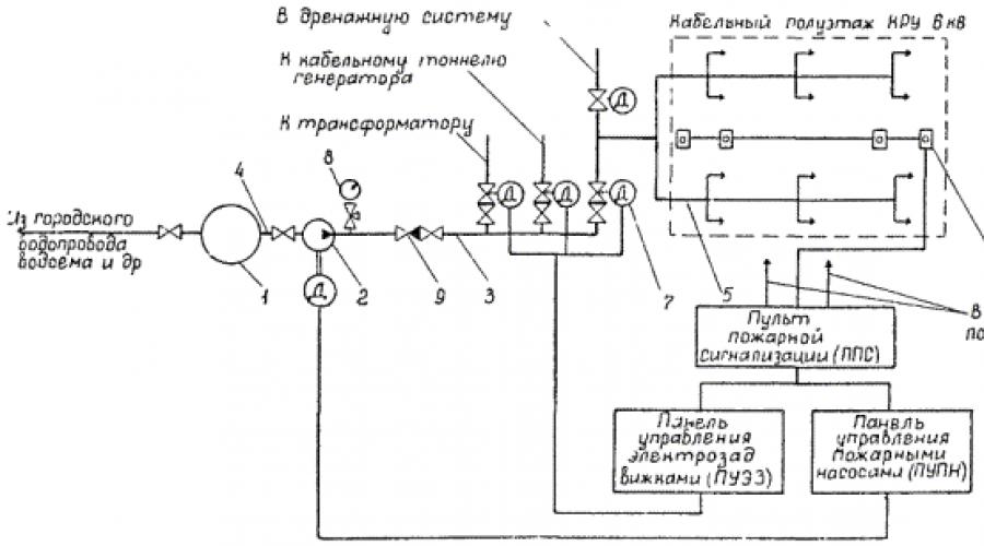
A schematic diagram of a water fire extinguishing installation is shown in the figure.
4.2. After graduation installation work suction, pressure and distribution pipelines must be flushed and hydraulically tested. The results of washing and pressing must be documented in reports (Appendices 1 and 2).
If possible, the effectiveness of the fire extinguishing installation should be checked by organizing extinguishing an artificial fire (Appendix 3).
Schematic diagram of a water fire extinguishing installation:
1 – water storage tank; 2 – fire pump (PF) with electric drive; 3 – pressure pipeline;
4 – suction pipeline; 5 – distribution pipeline; 6 – fire detector (PI);
7 – control unit; 8 – pressure gauge; 9 – check valve (OK)
Notese. Backup fire pump with fittings not shown.
4.3. When flushing pipelines, water should be supplied from their ends towards the control units (in order to prevent clogging of pipes with a smaller diameter) at a speed 15–20% higher than the speed of water in case of fire (determined by calculation or recommendations design organizations). Flushing should be continued until clean water appears steadily.
If it is impossible to flush certain sections of pipelines, it is permissible to purge them
dry, clean, compressed air or inert gas.
4.4. Hydraulic testing of pipelines must be carried out under a pressure equal to 1.25 working pressure (P), but not less than P+0.3 MPa, for 10 minutes.
To disconnect the tested section from the rest of the network, it is necessary to install blind flanges or plugs. It is not allowed to use existing control units, repair valves, etc. for this purpose.
After 10 minutes of testing, the pressure should be gradually reduced to working pressure and a thorough inspection of all welded joints and adjacent areas should be carried out.
The pipeline network is considered to have withstood hydraulic test, if no signs of rupture, leakage or drops are found in the welded joints and on the base metal, visible residual
deformations.
Pressure should be measured with two pressure gauges.
4.5. Flushing and hydraulic testing of pipelines must be carried out in conditions
preventing them from freezing.
It is prohibited to fill open trenches with pipelines that have been exposed to severe frosts, or to fill such trenches with frozen soil.
4.6. Automatic water fire extinguishing installations must operate in automatic start mode. For the period of personnel presence in cable structures (bypass, repair work
etc.) the start-up of installations should be switched to manual (remote) start-up (clause 3.2).
5. MAINTENANCE OF FIRE FIGHTING INSTALLATIONS
5.1. Organizational events
5.1.1. Persons responsible for operation, carrying out capital and current repairs technological equipment of the fire extinguishing installation are appointed by the head of the energy enterprise, who also approves schedules for technical supervision and repair of equipment.
5.1.2. The person responsible for the constant readiness of the technological equipment of a fire extinguishing installation must have a good knowledge of the design principle and operating procedure of this equipment,
and also have the following documentation:
project with changes made during installation and commissioning of the fire extinguishing installation;
factory passports and operating instructions for equipment and instruments;
this Standard Instruction and local operating instructions for technological equipment;
acts and protocols for conducting installation and commissioning work, as well as testing the operation of technological equipment;
schedules for maintenance and repair of process equipment;
“Logbook of maintenance and repair of fire extinguishing installations.”
5.1.3. Any deviations from accepted by the project diagrams, equipment replacement, additional
the installation of sprinklers or their replacement with sprinklers with a larger nozzle diameter must be previously agreed upon with the design institute - the author of the project.
5.1.4. To monitor the technical condition of the process equipment of the fire extinguishing installation, a “Logbook of maintenance and repair of the fire extinguishing installation” must be kept, in which the date and time of the inspection, who carried out the inspection, detected malfunctions, their nature and the time of their elimination, the time of forced shutdown and startup must be recorded. fire extinguishing installations, testing of the operation of the entire installation or individual equipment. An approximate form of the journal is given in Appendix 4.
At least once a quarter, the chief technical manager of the enterprise must familiarize himself with the contents of the magazine against receipt.
5.1.5. To check the readiness and effectiveness of the AUVP, a complete audit of the technological equipment of this installation must be carried out once every three years.
During the inspection, in addition to the main work, pressure testing of the pressure pipeline is carried out and in two or three directions, washing (or purging) and pressure testing of distribution pipelines (clauses 4.2–4.5) located in the most aggressive environment (dampness, gas contamination, dust) are carried out.
If deficiencies are detected, it is necessary to develop measures to ensure complete
eliminating them in a short time.
5.1.6. Automatic installation fire extinguishing in accordance with the schedule approved
by the head of the relevant workshop, but at least once every three years they must be tested (tested) according to a specially developed program with their actual putting into operation, provided that this
will not entail the shutdown of technological equipment or the entire production process. During testing on the first and last sprinklers, the water pressure and irrigation intensity should be checked.
Testing should be carried out for 1.5–2 minutes with the inclusion of working drainage devices.
Based on the test results, a report or protocol must be drawn up, and the fact of testing must be registered in the “Logbook of maintenance and repair of the fire extinguishing installation.”
5.1.7. Checking the operation of the AUVP or individual species equipment should be carried out during repair, maintenance of the protected premises and technological installation.
5.1.8. For storing spare equipment, equipment parts, and fixtures,
tools, materials, devices necessary for control and organization repair work AUVP, a special room must be allocated.
5.1.9. Technical capabilities AUVP should be included in the operational fire extinguishing plan
at this power plant. During fire drills, it is necessary to expand the circle of personnel who know the purpose and structure of the fire control system, as well as the procedure for putting it into action.
5.1.10. Personnel servicing AUVP compressors and pneumatic tanks must be trained and certified in accordance with the requirements of the Gosgortekhnadzor rules.
5.1.11. The person responsible for the operation of the process equipment of a fire extinguishing installation must organize training with the personnel allocated to control the operation and maintenance of this equipment.
5.1.12. In room pumping station AUVP must be posted: instructions on the procedure for putting pumps into operation and opening shut-off valves, as well as schematic and technological diagrams.
5.2. Technical requirements for AUVP
5.2.1. Entrances to the building (room) of the pumping station and fire extinguishing installation, as well as approaches to pumps, pneumatic tanks, compressors, control units, pressure gauges and other equipment of the fire extinguishing installation, must always be free.
5.2.2. In an operating fire extinguishing installation, they must be sealed in working order.
position:
hatches of tanks and containers for storing water supplies;
control units, valves and manual taps;
pressure switch;
drain taps.
5.2.3. After the fire extinguishing system has been activated, its functionality must be fully restored within 24 hours.
RUSSIAN JOINT STOCK COMPANY
SOCIETYENERGY
ANDELECTRIFICATION «
UESRUSSIA»
DEPARTMENTSCIENCEANDTECHNIQUES
TYPICALINSTRUCTIONS
BY
OPERATIONAUTOMATIC
INSTALLATIONS
WATERFIRE FIGHTING
RD 34.49.501-95
ORGRES
Moscow 1996
DevelopedJoint-stock company “Company for adjustment, improvement of technology and operation of power plants and networks “ORGRES”.
PerformersYES. ZAZAMLOV, A.N. IVANOV, A.S. KOZLOV, V.M. OLD PEOPLE
Agreedwith the Department of the General Inspectorate for the Operation of Power Plants and Networks of RAO UES of Russia on December 28, 1995.
Chief N.F. Gorev
ApprovedDepartment of Science and Technology of RAO UES of Russia December 29, 1995
Chief A.P. BERSENEV
|
STANDARD INSTRUCTIONS FOR OPERATING AUTOMATIC WATER FIRE FIGHTING UNITS |
RD 34.49.501-95 |
Expiration date set
from 01/01/97
This Standard Instruction provides the basic requirements for the operation of technological equipment of water fire extinguishing installations used at energy enterprises, and also sets out the procedure for flushing and pressure testing of pipelines of fire extinguishing installations. The scope and priority of monitoring the condition of process equipment, the timing of the inspection of all equipment of fire extinguishing installations are indicated, and basic recommendations for troubleshooting are given.
Responsibility for the operation of fire extinguishing installations is established, the necessary working documentation and requirements for personnel training are provided.
The basic safety requirements for the operation of fire extinguishing installations are indicated.
Forms for acts of flushing and pressure testing of pipelines and conducting fire tests are given.
With the release of this Standard Instruction, the “Standard Instructions for the Operation of Automatic Fire Extinguishing Installations: TI 34-00-046-85” (Moscow: SPO Soyuztekhenergo, 1985) becomes invalid.
1. INTRODUCTION
1.1 . The standard instructions establish requirements for the operation of technological equipment of water fire extinguishing installations and are mandatory for managers of energy enterprises, shop managers and persons appointed responsible for the operation of fire extinguishing installations.
1.2 . Technical requirements for the operation of technological equipment of foam fire extinguishing installations are set out in the “Instructions for the operation of fire extinguishing installations using air-mechanical foam” (M.: SPO ORGRES, 1997).
1.3 . When operating an automatic fire alarmfire extinguishing installations (AUP) should be guided by the “Standard Instructions for the Operation of Automatic Fire Alarm Installations at Energy Enterprises” (Moscow: SPO ORGRES, 1996).
The following abbreviations are adopted in this Standard Instruction.
UVP - water fire extinguishing installation,
AUP - automatic fire extinguishing installation,
AUVP - automatic water fire extinguishing installation,
PPS - fire alarm panel,
PUEZ - control panel for electric valves,
PUPN - fire pump control panel,
PI - fire detector,
PN - fire pump,
OK - check valve,
DV - water deluge,
DVM - modernized water drencher,
OPDR - foam-drencher sprinkler.
2. GENERAL INSTRUCTIONS
2.1 . Based on this Standard Instruction, the organization that carried out the adjustment of the process equipment of the automatic control system, together with the energy enterprise where this equipment is installed, must develop local instructions for the operation of the technological equipment and devices of the automatic control system. If the adjustment was carried out by an energy enterprise, then the instructions are developed by the personnel of this enterprise. Local instructions must be developed at least one month before the AUP is accepted into operation.
2.2 . The local instructions must take into account the requirements of this Standard Instruction and the requirements of factory passports and operating instructions for equipment, devices and equipment included in the AUVP. Reducing the requirements set out in these documents is not allowed.
2.3 . Local instructions must be revised at least once every three years and each time after the reconstruction of the AUP or in the event of a change in operating conditions.
2.4 . Acceptance of the AUP for operation must be carried out by representatives of:
energy enterprises (chairman);
design, installation and commissioning organizations;
state fire supervision.
The commission's work program and acceptance certificate must be approved by the chief technical manager of the enterprise.
3. SAFETY PRECAUTIONS
3.1 . When operating technological equipment of water fire extinguishing installations, personnel of energy enterprises must comply with the relevant safety requirements specified in PTE, PTB, as well as in factory data sheets and operating instructions for specific equipment.
3.2 . During maintenance and repair of the automatic control system, when visiting a room protected by the automatic control system, the automatic control of a specific distribution pipeline in this direction must be switched to manual (remote) until the last person leaves the room.
3.3 . Pressure testing of pipelines with water should be carried out only according to an approved program, which should include measures to ensure the protection of personnel from possible rupture of pipelines. It is necessary to ensure complete removal of air from the pipelines. Combining crimping work with other work in the same room is prohibited. If pressure testing is carried out by contractors, then the work is performed according to the work permit. The performance of these works by operational or maintenance personnel of the energy enterprise is documented in written order.
3.4 . Before starting work, personnel involved in pressure testing must undergo workplace safety training.
3.5 . There should be no unauthorized persons in the room during pressure testing. Pressure testing must be carried out under the supervision of a responsible person.
3.6 . Repair work on process equipment must be carried out after removing the pressure from this equipment and preparing the necessary organizational and technical measures established by the current safety regulations.
4. PREPARATION FOR OPERATION AND CHECKING THE TECHNICAL CONDITION OF THE FIRE FIGHTING INSTALLATION
4.1 . The water fire extinguishing installation consists of:
source of water supply (reservoir, pond, city water supply, etc.);
fire pumps (designed for collecting and supplying water to pressure pipelines);
suction pipelines (connecting the water source with fire pumps);
pressure pipelines (from the pump to the control unit);
distribution pipelines (laid within the protected premises);
control units installed at the end of pressure pipelines;
irrigators.
In addition to the above, based on design decisions, the following may be included in the fire extinguishing installation diagram:
a water tank for filling fire pumps;
a pneumatic tank to maintain constant pressure in the network of the fire extinguishing installation;
compressor for replenishing the pneumatic tank with air;
drain valves;
check valves;
dosing washers;
pressure switch;
pressure gauges;
vacuum gauges;
level gauges for measuring the level in tanks and pneumatic tanks;
other signaling, control and automation devices.
A schematic diagram of a water fire extinguishing installation is shown in the figure.
4.2 . After completion of installation work, suction, pressure and distribution pipelines must be washed and subjected to hydraulic tests. The results of washing and pressure testing must be documented in reports (appendices And ).
If possible, you should check the effectiveness of the fire extinguishing installation by organizing extinguishing an artificial fire (Appendix).
4.3 . When flushing pipelines, water should be supplied from themends towards the control units (in order to prevent clogging of pipes with a smaller diameter) at a speed of 15 - 20% greater than the speed of water in a fire (determined by calculations or recommendations of design organizations). Flushing should be continued until clean water appears steadily.
If it is impossible to flush certain sections of pipelines, it is permissible to blow them with dry, clean, compressed air or inert gas.

Schematic diagram of a water fire extinguishing installation:
1 - water storage tank; 2 - fire pump (PN) with electric drive; 3 - pressure pipeline; 4 - suction pipeline; 5 - distribution pipeline; 6 - fire detector (PI); 7 - control unit; 8 - pressure gauge; 9 - check valve (OK)
Note.The backup fire pump with fittings is not shown.
4.4 . Hydraulic testing of pipelines must be carried out under a pressure equal to 1.25 working pressure (P), but not less than P + 0.3 MPa, for 10 minutes.
To disconnect the section under test from the rest of the network, it is necessary to install blind flanges or plugs. It is not allowed to use existing control units, repair valves, etc. for this purpose.
After 10 minutes of testing, the pressure should be gradually reduced to working pressure and a thorough inspection of all welded joints and adjacent areas should be carried out.
The pipeline network is considered to have passed the hydraulic test if there are no signs of rupture, leaks, drops in welded joints or on the base metal, or visible residual deformations.
Pressure should be measured with two pressure gauges.
4.5 . Flushing and hydraulic testing of pipelines must be carried out under conditions that prevent them from freezing.
It is prohibited to fill open trenches with pipelines that have been exposed to severe frosts, or to fill such trenches with frozen soil.
4.6 . Automatic water fire extinguishing installations must operate in automatic start mode. During the period of personnel presence in cable structures (bypass, repair work, etc.), the start-up of installations must be switched to manual (remote) activation (clause ).
5. MAINTENANCE OF FIRE FIGHTING INSTALLATIONS
5.1 . Organizational events
5.1.1 . Persons responsible for the operation, overhaul and current repairs of process equipment of a fire extinguishing installation are appointed by the head of the energy enterprise, who also approves schedules for technical supervision and repair of equipment.
5.1.2 . The person responsible for the constant readiness of the technological equipment of a fire extinguishing installation must have a good knowledge of the design principle and operating procedure of this equipment, and also have the following documentation:
project with changes made during installation and commissioning of the fire extinguishing installation;
factory passports and operating instructions for equipment and instruments;
this Standard Instruction and local operating instructions for process equipment;
acts and protocols for conducting installation and commissioning work, as well as testing the operation of technological equipment;
schedules for maintenance and repair of process equipment;
“Logbook of maintenance and repair of fire extinguishing installations.”
5.1.3 . Any deviations from the scheme adopted by the project, replacement of equipment, additional installation of sprinklers or their replacement with sprinklers with a larger nozzle diameter must be previously agreed upon with the design institute - the author of the project.
5.1.4 . To monitor the technical condition of the process equipment of the fire extinguishing installation, a “Logbook of maintenance and repair of the fire extinguishing installation” must be kept, in which the date and time of the inspection, who carried out the inspection, detected malfunctions, their nature and the time of their elimination, the time of forced shutdown and startup must be recorded. fire extinguishing installations, testing of the operation of the entire installation or individual equipment. An approximate form of the journal is given in the appendix .
At least once a quarter, the chief technical manager of the enterprise must familiarize himself with the contents of the magazine against receipt.
5.1.5 . To check the readiness and effectiveness of the AUVP, a complete audit of the technological equipment of this installation must be carried out once every three years.
During the inspection, in addition to the main work, pressure testing of the pressure pipeline is carried out and in two or three directions, washing (or purging) and pressure testing of distribution pipelines (points -) located in the most aggressive environment (dampness, gas contamination, dust) are carried out.
If deficiencies are discovered, it is necessary to develop measures to ensure their complete elimination in a short time.
5.1.6 . Automatic fire extinguishing installations in accordance with the schedule approved by the head of the relevant workshop, but at least once every three years, must be tested (tested) according to a specially developed program with their actual commissioning, provided that this does not entail a shutdown of the process equipment or the entire production process. During testing on the first and last sprinklers, the water pressure and irrigation intensity should be checked.
Testing should be carried out for 1.5 - 2 minutes with the inclusion of serviceable drainage devices.
Based on the test results, a report or protocol must be drawn up, and the fact of testing must be registered in the “Logbook of maintenance and repair of the fire extinguishing installation.”
5.1.7 . The operation of the AUVP or individual types of equipment should be checked during repairs, maintenance of the protected premises and technological installation.
5.1.8 . A special room must be allocated for storing spare equipment, equipment parts, as well as devices, tools, materials, instruments necessary for monitoring and organizing repair work of the AUVP.
5.1.9 . The technical capabilities of the AUVP should be included in the operational plan for extinguishing a fire at a given energy enterprise. During fire drills, it is necessary to expand the circle of personnel who know the purpose and structure of the fire control system, as well as the procedure for putting it into action.
5.1.10 . Personnel servicing AUVP compressors and pneumatic tanks must be trained and certified in accordance with the requirements of the Gosgortekhnadzor rules.
5.1.11 . The person responsible for the operation of the process equipment of a fire extinguishing installation must organize training with the personnel allocated to control the operation and maintenance of this equipment.
5.1.12 . In the premises of the AUVP pumping station, the following must be posted: instructions on the procedure for putting pumps into operation and open shut-off valves, as well as schematic and technological diagrams.
5.2 . Technical requirements for AUVP
5.2.1 . Entrances to the building (room) of the pumping station and fire extinguishing installation, as well as approaches to pumps, pneumatic tanks, compressors, control units, pressure gauges and other equipment of the fire extinguishing installation, must always be free.
5.2.2 . In an operating fire extinguishing installation, the following must be sealed in the operating position:
hatches of tanks and containers for storing water supplies;
control units, valves and manual taps;
pressure switch;
drain taps.
5.2.3 . After the fire extinguishing system has been activated, its functionality must be fully restored no later than 24 hours later.
5.3 . Water storage tanks
5.3.1 . Checking the water level in the tank must be carried out daily and recorded in the “Logbook of maintenance and repair of the fire extinguishing installation.”
If the water level decreases due to evaporation, it is necessary to add water, if there are leaks, determine the location of damage to the tank and eliminate the leaks.
5.3.2 . The serviceability of the automatic level gauge in the tank must be checked at least once every three months at positive temperatures, monthly - at negative temperature and immediately in case of doubt about the proper operation of the level gauge.
5.3.3 . Tanks must be closed to access by unauthorized persons and sealed; the integrity of the seal is checked during the inspection of the equipment, but at least once a quarter.
5.3.4 . The water in the tank should not contain mechanical impurities that could clog pipelines, dosing washers and sprinklers.
5.3.5 . To prevent decay and blooming of water, it is recommended to disinfect it with bleach at the rate of 100 g of lime per 1 m 3 of water.
5.3.6 . The water in the tank must be replaced annually in the fall.her time. When replacing water, the bottom and internal walls tanks are cleaned of dirt and build-up, damaged paint is restored or completely renewed.
5.3.7 . Before the onset of frost in buried tanks, the gap between the lower and upper hatch covers must be filled with insulating material.
5.4 . Suction line
5.4.1 . Once a quarter the condition of the inputs, shut-off valves, measuring instruments and a water intake well.
5.4.2 . Before the onset of frost, the fittings in the water intake well must be inspected, repaired if necessary, and the well insulated.
5.5 . Pumping station
5.5.1 . Before testing the pumps, it is necessary to check: the tightness of the seals; lubricant level in bearing baths; correct tightening of foundation bolts, pump cover nuts and bearings; connections of the piping on the suction side and the pumps themselves.
5.5.2 . Once a month, pumps and other equipment of the pumping station must be inspected and cleaned of dust and dirt.
5.5.3 . Each fire pump must be turned on at least twice a month to create the required pressure, which is recorded in the operational log.
5.5.4 . At least once a month, the reliability of transferring all fire pumps to the main and backup power supply should be checked and the results recorded in the operational log.
5.5.5 . If there is a special tank for filling pumps with water, the latter must be inspected and painted annually.
5.5.6 . Once every three years, pumps and motors in accordance with paragraph. . of this Standard Instruction must undergo an audit, during which all existing deficiencies are eliminated.
Repair and replacement of worn parts, checking of seals are carried out as necessary.
5.5.7 . The pumping station premises must be kept clean. When not on duty, it must be locked. One of the spare keys must be stored on the control panel, as indicated on the door.
5.6 . Pressure and distribution pipelines
5.6.1 . Once a quarter you need to check:
absence of leaks and deflections of pipelines;
the presence of a constant slope (at least 0.01 for pipes with a diameter of up to 50 mm and 0.005 for pipes with a diameter of 50 mm or more);
condition of pipeline fastenings;
no contact with electrical wires and cables;
condition of painting, absence of dirt and dust.
Detected deficiencies that may affect the reliability of the installation must be corrected immediately.
5.6.2 . The pressure pipeline must be in constant readiness for action, i.e. filled with water and under operating pressure.
5.7 . Control units and shut-off valves
5.7.1 . For AUVP transformers and cable structures in shut-off and start-up devices, steel fittings should be used: electrified gate valves with automatic start-up, brand 30s 941nzh; 30s 986nzh; 30s 996nzh with a working pressure of 1.6 MPa, repair valves with manual drive brand 30s 41nzh with a working pressure of 1.6 MPa.
5.7.2 . The condition of control units and shut-off valves, the presence of seals, and pressure values before and after control units must be monitored at least once a month.
5.7.3 . An inspection must be carried out once every six months electrical diagram activation of the control unit with its automatic activation from the fire detector when the valve is closed.
5.7.4 . The installation site of the control unit must be well lit, the inscriptions on the pipelines or special stencils (node number, protected area, type of sprinklers and their quantity) must be made with indelible bright paint and be clearly visible.
5.7.5 . All damage to valves, valves and check valves that may affect the reliability of the fire extinguishing installation must be repaired immediately.
5.8 . Sprinklers
5.8.1 . As water sprinklers for automatic fire extinguishing transformers use OPDR-15 sprinklers with a working water pressure in front of the sprinklers in the range of 0.2 - 0.6 MPa; for automatic fire extinguishing cable structures sprinklers DV, DVM with a working pressure of 0.2 - 0.4 MPa are used.
5.8.2 . When inspecting the equipment distribution devices, but at least once a month, sprinklers must be inspected and cleaned of dust and dirt. If a malfunction or corrosion is detected, measures must be taken to eliminate it.
5.8.3 . When carrying out repair work, sprinklers must be protected from contact with plaster and paint (for example, with polyethylene or paper caps, etc.). Traces of paint and mortar found after repair must be removed.
5.8.4 . It is prohibited to install plugs or plugs in place of faulty sprinklers.
5.8.5 . To replace faulty or damaged sprinklers, a reserve of 10 - 15% should be created total number installed sprinklers.
5.9 . Air tank and compressor
5.9.1 . Putting the pneumatic tank into operation must be done in the following sequence:
fill the pneumatic tank with water to approximately 50% of its volume (check the level using the water gauge glass);
turn on the compressor or open the valve on the compressed air pipeline;
raise the pressure in the pneumatic tank to operating pressure (controlled by a pressure gauge), after which the pneumatic tank is connected to the pressure pipeline, creating working pressure in it.
5.9.2 . Every day you should carry out an external inspection of the air tank, check the water level and air pressure in the air tank. When the air pressure decreases by 0.05 MPa (relative to the working one), it is pumped up.
Once a week the compressor is tested at idle.
5.9.3 . Maintenance air tank and compressor, carried out once a year, includes:
Emptying, inspecting and cleaning the air tank:
removal and testing on a bench safety valve(if faulty, replace with a new one);
painting the surface of the air tank (indicate the date of repair on the surface);
detailed inspection of the compressor (replace worn parts and fittings);
fulfillment of all others technical requirements provided by the manufacturer's data sheets and operating instructions for the pneumatic tank and compressor.
5.9.4 . Disconnecting the pneumatic tank from the fire extinguishing installation circuit is prohibited.
5.9.5 . The inspection of the pneumatic tank is carried out by a special commission with the participation of representatives of Gosgortekhnadzor, local bodies of the State Fire Supervision and the given energy enterprise.
Note.The compressor must only be started manually. In this case, it is necessary to monitor the level in the air tank, since when the compressor is automatically turned on, it is possible that water can be squeezed out of the air tank and even from the network by air.
5.10 . Pressure gauges
5.10.1 . The correct operation of pressure gauges installed on pneumatic tanks should be checked once a month; those installed on pipelines should be checked once every six months.
5.10.2 . A complete check at the fire extinguishing installation of all pressure gauges with their sealing or branding must be carried out annually in accordance with the current regulations.
6. ORGANIZATION AND REQUIREMENTS FOR REPAIR WORK
6.1 . When repairing process equipment of a fire extinguishing installation, one should, first of all, be guided by the requirements of the passport, the plant’s instructions for operating specific equipment, the requirements of the relevant standards and technical conditions, as well as the requirements of this Standard Instruction.
6.2 . When replacing a section of pipeline at a bend, the minimum radius of the internal bend curve steel pipes must be atbending them in a cold state with at least four outer diameters, in a hot state - at least three.
There should be no folds, cracks or other defects on the curved part of the pipe. Ovality in places of bending is allowed no more than 10% (determined by the ratio of the difference between the largest and smallest outer diameters of the bent pipe to the outer diameter of the pipe before the bend).
6.3 . The difference in thickness and displacement of the edges of joined pipes and pipeline parts should not exceed 10% of the wall thickness and should not exceed 3 mm.
6.4 . Before welding, the edges of the pipe ends to be welded and the surfaces adjacent to them must be cleaned of rust and dirt to a width of at least 20 mm.
6.5 . Welding of each joint must be performed without interruption until the entire joint is completely welded.
6.6 . The welded pipe joint must be rejected if the following defects are detected:
cracks extending to the surface of the weld or base metal in the welding zone;
sagging or undercuts in the transition zone from the base metal to the deposited metal;
burns;
unevenness of the weld seam in width and height, as well as its deviations from the axis.
6.7 . In particularly damp rooms with a chemically active environment, pipeline fastening structures must be made of steel profiles with a thickness of at least 4 mm. Pipelines and fastening structures must be coated with protective varnish or paint.
6.8 . Pipeline connections during open installation must be located outside walls, partitions, ceilings and other building structures of buildings.
6.9 . The fastening of pipelines to the building structures must be carried out using normalized supports and hangers. Welding pipelines directly to metal structures buildings and structures, as well as elements of technological equipment is not allowed.
6.10 . Welding of supports and hangers to building structures must be carried out without weakening their mechanical strength.
6.11 . Sagging and bending of pipelines is not allowed.
6.12 . Each turn of a pipeline longer than 0.5 m musthave a mount. The distance from hangers to welded and threaded joints of pipes must be at least 100 mm.
6.13 . Newly installed sprinklers must be cleaned of preservative grease and tested with a hydraulic pressure of 1.25 MPa (12.5 kgf/cm2) for 1 minute.
The average service life of sprinklers is determined to be at least 10 years.
6.14 . The performance of sprinklers DV, DVM and OPDR-15 is given in table. .
Table 1
|
Outlet diameter, mm |
Sprinkler capacity, l/s, at pressure MPa |
||||
|
DV-10 and DVM-10 |
|||||
|
OPDR-15 |
|||||
7. SPECIFIC FAULTS AND METHODS FOR THEIR ELIMINATION
7.1 . Possible faults in the operation of a water fire extinguishing installation and recommendations for eliminating them are given in Table. .
table 2
|
Water does not come out of the sprinklers, the pressure gauge shows normal pressure |
The valve is closed |
Open the valve |
|
Check valve stuck |
Open check valve |
|
|
The pipeline is clogged |
Clean the pipeline |
|
|
Sprinklers are clogged |
Clear the blockage |
|
|
Water does not come out of the sprinklers, the pressure gauge does not show pressure |
The fire pump did not start working |
Turn on the fire pump |
|
The valve on the pipeline on the suction side of the fire pump is closed |
Open the valve |
|
|
There is an air leak on the suction side of the fire pump |
Troubleshoot connection problems |
|
|
Wrong direction of rotor rotation |
Switch motor phases |
|
|
A valve in the other direction is accidentally opened |
Close the valve in the other direction |
|
|
Leakage of water through welds, in places of connection of control units and sprinklers |
Poor quality welding |
Check quality welds |
|
The gasket is worn out |
Replace gasket |
|
|
Loose bolts |
Tighten the bolts |
|
|
No pressure gauge reading |
There is no pressure in the pipeline |
Restore pressure in the pipeline |
|
The inlet is clogged |
Remove the pressure gauge and clean the hole |
|
|
Sparking pressure gauge contacts |
Contamination of pressure gauge contacts |
Remove the pressure gauge glass and clean the contacts |
Annex 1
ACT
| ||||||||||||||||||||||||||||||||||||||||||||||||||||||
|
STANDARD INSTRUCTIONS FOR OPERATING AUTOMATIC WATER FIRE FIGHTING UNITS |
RD 34.49.501-95 |
Expiration date set
from 01/01/97
This Standard Instruction provides the basic requirements for the operation of technological equipment of water fire extinguishing installations used at energy enterprises, and also sets out the procedure for flushing and pressure testing of pipelines of fire extinguishing installations. The scope and priority of monitoring the condition of process equipment, the timing of the inspection of all equipment of fire extinguishing installations are indicated, and basic recommendations for troubleshooting are given.
Responsibility for the operation of fire extinguishing installations is established, the necessary working documentation and requirements for personnel training are provided.
The basic safety requirements for the operation of fire extinguishing installations are indicated.
Forms for acts of flushing and pressure testing of pipelines and conducting fire tests are given.
With the release of this Standard Instruction, the “Standard Instructions for the Operation of Automatic Fire Extinguishing Installations: TI 34-00-046-85” (Moscow: SPO Soyuztekhenergo, 1985) becomes invalid.
1. INTRODUCTION
1.1. The standard instructions establish requirements for the operation of technological equipment of water fire extinguishing installations and are mandatory for managers of energy enterprises, shop managers and persons appointed responsible for the operation of fire extinguishing installations.
1.2. Technical requirements for the operation of technological equipment of foam fire extinguishing installations are set out in the “Instructions for the operation of fire extinguishing installations using air-mechanical foam” (M.: SPO ORGRES, 1997).
1.3. When operating the fire alarm of an automatic fire extinguishing installation (AUP), one should be guided by the “Standard Instructions for the Operation of Automatic Fire Alarm Installations at Energy Enterprises” (Moscow: SPO ORGRES, 1996).
The following abbreviations are adopted in this Standard Instruction.
UVP - water fire extinguishing installation,
AUP - automatic fire extinguishing installation,
AUVP - automatic water fire extinguishing installation,
PPS - fire alarm panel,
PUEZ - control panel for electric valves,
PUPN - fire pump control panel,
PI - fire detector,
PN - fire pump,
OK - check valve,
DV - water deluge,
DVM - modernized water drencher,
OPDR - foam-drencher sprinkler.
2. GENERAL INSTRUCTIONS
2.1. Based on this Standard Instruction, the organization that carried out the adjustment of the process equipment of the automatic control system, together with the energy enterprise where this equipment is installed, must develop local instructions for the operation of the technological equipment and devices of the automatic control system. If the adjustment was carried out by an energy enterprise, then the instructions are developed by the personnel of this enterprise. Local instructions must be developed at least one month before the AUP is accepted into operation.
2.2. The local instructions must take into account the requirements of this Standard Instruction and the requirements of factory passports and operating instructions for equipment, devices and equipment included in the AUVP. Reducing the requirements set out in these documents is not allowed.
2.3. Local instructions must be revised at least once every three years and each time after the reconstruction of the AUP or in the event of a change in operating conditions.
2.4. Acceptance of the AUP for operation must be carried out by representatives of:
energy enterprises (chairman);
design, installation and commissioning organizations;
state fire supervision.
The commission's work program and acceptance certificate must be approved by the chief technical manager of the enterprise.
3. SAFETY PRECAUTIONS
3.1. When operating technological equipment of water fire extinguishing installations, personnel of energy enterprises must comply with the relevant safety requirements specified in PTE, PTB, as well as in factory data sheets and operating instructions for specific equipment.
3.2. During maintenance and repair of the automatic control system, when visiting a room protected by the automatic control system, the automatic control of a specific distribution pipeline in this direction must be switched to manual (remote) until the last person leaves the room.
3.3. Pressure testing of pipelines with water should be carried out only according to an approved program, which should include measures to ensure the protection of personnel from possible rupture of pipelines. It is necessary to ensure complete removal of air from the pipelines. Combining crimping work with other work in the same room is prohibited. If pressure testing is carried out by contractors, then the work is performed according to the work permit. The performance of these works by operational or maintenance personnel of the energy enterprise is documented in written order.
3.4. Before starting work, personnel involved in pressure testing must undergo workplace safety training.
3.5. There should be no unauthorized persons in the room during pressure testing. Pressure testing must be carried out under the supervision of a responsible person.
3.6. Repair work on process equipment must be carried out after removing the pressure from this equipment and preparing the necessary organizational and technical measures established by the current safety regulations.
4. PREPARATION FOR OPERATION AND CHECKING THE TECHNICAL CONDITION OF THE FIRE FIGHTING INSTALLATION
4.1. The water fire extinguishing installation consists of:
source of water supply (reservoir, pond, city water supply, etc.);
fire pumps (designed for collecting and supplying water to pressure pipelines);
suction pipelines (connecting the water source with fire pumps);
pressure pipelines (from the pump to the control unit);
distribution pipelines (laid within the protected premises);
control units installed at the end of pressure pipelines;
irrigators.
In addition to the above, based on design decisions, the following may be included in the fire extinguishing installation diagram:
a water tank for filling fire pumps;
a pneumatic tank to maintain constant pressure in the network of the fire extinguishing installation;
compressor for replenishing the pneumatic tank with air;
drain valves;
check valves;
dosing washers;
pressure switch;
pressure gauges;
vacuum gauges;
level gauges for measuring the level in tanks and pneumatic tanks;
other signaling, control and automation devices.
A schematic diagram of a water fire extinguishing installation is shown in the figure.
4.2. After completion of installation work, suction, pressure and distribution pipelines must be washed and subjected to hydraulic tests. The results of washing and pressure testing must be documented in reports (appendices and).
If possible, you should check the effectiveness of the fire extinguishing installation by organizing extinguishing an artificial fire (Appendix).
4.3. When flushing pipelines, water should be supplied from their ends towards the control units (in order to prevent clogging of pipes with a smaller diameter) at a speed 15 - 20% higher than the speed of water in a fire (determined by calculations or recommendations of design organizations). Flushing should be continued until clean water appears steadily.
If it is impossible to flush certain sections of pipelines, it is permissible to blow them with dry, clean, compressed air or inert gas.

Schematic diagram of a water fire extinguishing installation:
1 - water storage tank; 2 - fire pump (PN) with electric drive; 3 - pressure pipeline; 4 - suction pipeline; 5 - distribution pipeline; 6 - fire detector (PI); 7 - control unit; 8 - pressure gauge; 9 - check valve (OK)
Note. The backup fire pump with fittings is not shown.
4.4. Hydraulic testing of pipelines must be carried out under a pressure equal to 1.25 working pressure (P), but not less than P + 0.3 MPa, for 10 minutes.
To disconnect the tested section from the rest of the network, it is necessary to install blind flanges or plugs. It is not allowed to use existing control units, repair valves, etc. for this purpose.
After 10 minutes of testing, the pressure should be gradually reduced to working pressure and a thorough inspection of all welded joints and adjacent areas should be carried out.
The pipeline network is considered to have passed the hydraulic test if there are no signs of rupture, leaks, drops in welded joints or on the base metal, or visible residual deformations.
Pressure should be measured with two pressure gauges.
4.5. Flushing and hydraulic testing of pipelines must be carried out under conditions that prevent them from freezing.
It is prohibited to fill open trenches with pipelines that have been exposed to severe frosts, or to fill such trenches with frozen soil.
4.6. Automatic water fire extinguishing installations must operate in automatic start mode. During the period of personnel presence in cable structures (bypass, repair work, etc.), the start-up of installations must be switched to manual (remote) switching (p.).
5. MAINTENANCE OF FIRE FIGHTING INSTALLATIONS
5.1 . Organizational events
5.1.1. Persons responsible for the operation, overhaul and current repairs of process equipment of a fire extinguishing installation are appointed by the head of the energy enterprise, who also approves schedules for technical supervision and repair of equipment.
5.1.2. The person responsible for the constant readiness of the technological equipment of a fire extinguishing installation must have a good knowledge of the design principle and operating procedure of this equipment, and also have the following documentation:
project with changes made during installation and commissioning of the fire extinguishing installation;
factory passports and operating instructions for equipment and instruments;
this Standard Instruction and local operating instructions for process equipment;
acts and protocols for conducting installation and commissioning work, as well as testing the operation of technological equipment;
schedules for maintenance and repair of process equipment;
“Logbook of maintenance and repair of fire extinguishing installations.”
5.1.3. Any deviations from the scheme adopted by the project, replacement of equipment, additional installation of sprinklers or their replacement with sprinklers with a larger nozzle diameter must be previously agreed upon with the design institute - the author of the project.
5.1.4. To monitor the technical condition of the process equipment of the fire extinguishing installation, a “Logbook of maintenance and repair of the fire extinguishing installation” must be kept, in which the date and time of the inspection, who carried out the inspection, detected malfunctions, their nature and the time of their elimination, the time of forced shutdown and startup must be recorded. fire extinguishing installations, testing of the operation of the entire installation or individual equipment. An approximate form of the journal is given in the Appendix.
At least once a quarter, the chief technical manager of the enterprise must familiarize himself with the contents of the magazine against receipt.
5.1.5. To check the readiness and effectiveness of the AUVP, a complete audit of the technological equipment of this installation must be carried out once every three years.
During the inspection, in addition to the main work, pressure testing of the pressure pipeline is carried out and in two or three directions, washing (or purging) and pressure testing of distribution pipelines (points -) located in the most aggressive environment (dampness, gas contamination, dust) are carried out.
If deficiencies are discovered, it is necessary to develop measures to ensure their complete elimination in a short time.
5.1.6. Automatic fire extinguishing installations in accordance with the schedule approved by the head of the relevant workshop, but at least once every three years, must be tested (tested) according to a specially developed program with their actual commissioning, provided that this does not entail a shutdown of the process equipment or the entire production process. During testing on the first and last sprinklers, the water pressure and irrigation intensity should be checked.
Testing should be carried out for 1.5 - 2 minutes with the inclusion of serviceable drainage devices.
Based on the test results, a report or protocol must be drawn up, and the fact of testing must be registered in the “Logbook of maintenance and repair of the fire extinguishing installation.”
5.1.7. The operation of the AUVP or individual types of equipment should be checked during repairs, maintenance of the protected premises and technological installation.
5.1.8. A special room must be allocated for storing spare equipment, equipment parts, as well as devices, tools, materials, instruments necessary for monitoring and organizing repair work of the AUVP.
5.1.9. The technical capabilities of the AUVP should be included in the operational plan for extinguishing a fire at a given energy enterprise. During fire drills, it is necessary to expand the circle of personnel who know the purpose and structure of the fire control system, as well as the procedure for putting it into action.
5.1.10. Personnel servicing AUVP compressors and pneumatic tanks must be trained and certified in accordance with the requirements of the Gosgortekhnadzor rules.
5.1.11. The person responsible for the operation of the process equipment of a fire extinguishing installation must organize training with the personnel allocated to control the operation and maintenance of this equipment.
5.1.12. In the premises of the AUVP pumping station, the following must be posted: instructions on the procedure for putting pumps into operation and open shut-off valves, as well as schematic and technological diagrams.
5.2 . Technical requirements for AUVP
5.2.1. Entrances to the building (room) of the pumping station and fire extinguishing installation, as well as approaches to pumps, pneumatic tanks, compressors, control units, pressure gauges and other equipment of the fire extinguishing installation, must always be free.
5.2.2. In an operating fire extinguishing installation, the following must be sealed in the operating position:
hatches of tanks and containers for storing water supplies;
control units, valves and manual taps;
pressure switch;
drain taps.
5.2.3. After the fire extinguishing system has been activated, its functionality must be fully restored no later than 24 hours later.
5.3 . Water storage tanks
5.3.1. Checking the water level in the tank must be carried out daily and recorded in the “Logbook of maintenance and repair of the fire extinguishing installation.”
If the water level decreases due to evaporation, it is necessary to add water, if there are leaks, determine the location of damage to the tank and eliminate the leaks.
5.3.2. The proper operation of the automatic level gauge in the tank must be checked at least once every three months at positive temperatures, monthly at negative temperatures, and immediately in case of doubt about the proper operation of the level gauge.
5.3.3. Tanks must be closed to access by unauthorized persons and sealed; the integrity of the seal is checked during the inspection of the equipment, but at least once a quarter.
5.3.4. The water in the tank should not contain mechanical impurities that could clog pipelines, dosing washers and sprinklers.
5.3.5. To prevent water from rotting and blooming, it is recommended to disinfect it with bleach at the rate of 100 g of lime per 1 m3 of water.
5.3.6. The water in the tank must be replaced annually in the fall. When replacing water, the bottom and inner walls of the tank are cleaned of dirt and build-up, and damaged paint is restored or completely renewed.
5.3.7. Before the onset of frost in buried tanks, the gap between the lower and upper hatch covers must be filled with insulating material.
5.4 . Suction line
5.4.1. Once a quarter, the condition of the inputs, shut-off valves, measuring instruments and water intake well is checked.
5.4.2. Before the onset of frost, the fittings in the water intake well must be inspected, repaired if necessary, and the well insulated.
5.5 . Pumping station
5.5.1. Before testing the pumps, it is necessary to check: the tightness of the seals; lubricant level in bearing baths; correct tightening of foundation bolts, pump cover nuts and bearings; connections of the pipeline on the suction side and the pumps themselves.
5.5.2. Once a month, pumps and other equipment of the pumping station must be inspected and cleaned of dust and dirt.
5.5.3. Each fire pump must be turned on at least twice a month to create the required pressure, which is recorded in the operational log.
5.5.4. At least once a month, the reliability of transferring all fire pumps to the main and backup power supply should be checked and the results recorded in the operational log.
5.5.5. If there is a special tank for filling pumps with water, the latter must be inspected and painted annually.
5.5.6. Once every three years, pumps and motors in accordance with clause. of this Standard Instruction must undergo an audit, during which all existing deficiencies are eliminated.
Repair and replacement of worn parts, checking of seals are carried out as necessary.
5.5.7. The pumping station premises must be kept clean. When not on duty, it must be locked. One of the spare keys must be stored on the control panel, as indicated on the door.
5.6 . Pressure and distribution pipelines
5.6.1. Once a quarter you need to check:
absence of leaks and deflections of pipelines;
the presence of a constant slope (at least 0.01 for pipes with a diameter of up to 50 mm and 0.005 for pipes with a diameter of 50 mm or more);
condition of pipeline fastenings;
no contact with electrical wires and cables;
condition of painting, absence of dirt and dust.
Detected deficiencies that may affect the reliability of the installation must be corrected immediately.
5.6.2. The pressure pipeline must be in constant readiness for action, i.e. filled with water and under operating pressure.
5.7 . Control units and shut-off valves
5.7.1. For AUVP transformers and cable structures in shut-off and start-up devices, steel fittings should be used: electrified gate valves with automatic start-up, brand 30s 941nzh; 30s 986nzh; 30s 996nzh with a working pressure of 1.6 MPa, repair valves with manual drive brand 30s 41nzh with a working pressure of 1.6 MPa.
5.7.2. The condition of control units and shut-off valves, the presence of seals, and pressure values before and after control units must be monitored at least once a month.
5.7.3. Once every six months, the electrical circuit of the control unit should be checked with its automatic activation from the fire detector when the valve is closed.
5.7.4. The installation site of the control unit must be well lit, the inscriptions on the pipelines or special stencils (node number, protected area, type of sprinklers and their quantity) must be made with indelible bright paint and be clearly visible.
5.7.5. All damage to valves, valves and check valves that may affect the reliability of the fire extinguishing installation must be repaired immediately.
5.8 . Sprinklers
5.8.1. OPDR-15 sprinklers with a working water pressure in front of the sprinklers in the range of 0.2 - 0.6 MPa are used as water sprinklers for automatic fire extinguishing of transformers; For automatic fire extinguishing of cable structures, DV, DVM sprinklers with a working pressure of 0.2 - 0.4 MPa are used.
5.8.2. When inspecting switchgear equipment, but at least once a month, sprinklers must be inspected and cleaned of dust and dirt. If a malfunction or corrosion is detected, measures must be taken to eliminate it.
5.8.3. When carrying out repair work, sprinklers must be protected from contact with plaster and paint (for example, with polyethylene or paper caps, etc.). Traces of paint and mortar found after repair must be removed.
5.8.5. To replace faulty or damaged sprinklers, a reserve of 10 - 15% of the total number of installed sprinklers should be created.
5.9 . Air tank and compressor
5.9.1. Putting the pneumatic tank into operation must be done in the following sequence:
fill the pneumatic tank with water to approximately 50% of its volume (check the level using the water gauge glass);
turn on the compressor or open the valve on the compressed air pipeline;
raise the pressure in the pneumatic tank to operating pressure (controlled by a pressure gauge), after which the pneumatic tank is connected to the pressure pipeline, creating working pressure in it.
5.9.2. Every day you should carry out an external inspection of the air tank, check the water level and air pressure in the air tank. When the air pressure decreases by 0.05 MPa (relative to the working one), it is pumped up.
Once a week the compressor is tested at idle.
5.9.3. Maintenance of the air tank and compressor, carried out once a year, includes:
Emptying, inspecting and cleaning the air tank:
removing and testing the safety valve on a bench (if faulty, replace it with a new one);
painting the surface of the air tank (indicate the date of repair on the surface);
detailed inspection of the compressor (replace worn parts and fittings);
fulfillment of all other technical requirements stipulated by the factory passports and operating instructions for the pneumatic tank and compressor.
5.9.4. Disconnecting the pneumatic tank from the fire extinguishing installation circuit is prohibited.
5.9.5. The inspection of the pneumatic tank is carried out by a special commission with the participation of representatives of Gosgortekhnadzor, local bodies of the State Fire Supervision and the given energy enterprise.
Note. The compressor must only be started manually. In this case, it is necessary to monitor the level in the air tank, since when the compressor is automatically turned on, it is possible that water can be squeezed out of the air tank and even from the network by air.
5.10 . Pressure gauges
5.10.1. The correct operation of pressure gauges installed on pneumatic tanks should be checked once a month; those installed on pipelines should be checked once every six months.
5.10.2. A complete check at the fire extinguishing installation of all pressure gauges with their sealing or branding must be carried out annually in accordance with the current regulations.
6. ORGANIZATION AND REQUIREMENTS FOR REPAIR WORK
6.1. When repairing process equipment of a fire extinguishing installation, one should, first of all, be guided by the requirements of the passport, the plant’s instructions for operating specific equipment, the requirements of the relevant standards and technical conditions, as well as the requirements of this Standard Instruction.
6.2. When replacing a section of a pipeline at a bend, the minimum radius of the internal bending curve of steel pipes must be at least four outer diameters when bending in a cold state, and at least three in a hot state.
There should be no folds, cracks or other defects on the curved part of the pipe. Ovality in places of bending is allowed no more than 10% (determined by the ratio of the difference between the largest and smallest outer diameters of the bent pipe to the outer diameter of the pipe before the bend).
6.3. The difference in thickness and displacement of the edges of joined pipes and pipeline parts should not exceed 10% of the wall thickness and should not exceed 3 mm.
6.4. Before welding, the edges of the pipe ends to be welded and the surfaces adjacent to them must be cleaned of rust and dirt to a width of at least 20 mm.
6.5. Welding of each joint must be performed without interruption until the entire joint is completely welded.
6.6. The welded pipe joint must be rejected if the following defects are detected:
cracks extending to the surface of the weld or base metal in the welding zone;
sagging or undercuts in the transition zone from the base metal to the deposited metal;
burns;
unevenness of the weld seam in width and height, as well as its deviations from the axis.
6.7. In particularly damp rooms with a chemically active environment, pipeline fastening structures must be made of steel profiles with a thickness of at least 4 mm. Pipelines and fastening structures must be coated with protective varnish or paint.
6.8. Pipeline connections during open installation must be located outside walls, partitions, ceilings and other building structures of buildings.
6.9. The fastening of pipelines to the building structures must be carried out using normalized supports and hangers. Welding pipelines directly to metal structures of buildings and structures, as well as elements of process equipment, is not permitted.
6.10. Welding of supports and hangers to building structures must be carried out without weakening their mechanical strength.
6.11. Sagging and bending of pipelines is not allowed.
6.12. Each pipeline bend longer than 0.5 m must have a fastening. The distance from hangers to welded and threaded joints of pipes must be at least 100 mm.
6.13. Newly installed sprinklers must be cleaned of preservative grease and tested with a hydraulic pressure of 1.25 MPa (12.5 kgf/cm2) for 1 minute.
The average service life of sprinklers is determined to be at least 10 years.
6.14. The performance of sprinklers DV, DVM and OPDR-15 is given in table. .
Table 1
|
Outlet diameter, mm |
Sprinkler capacity, l/s, at pressure MPa |
||||||||||||||||||||||||||||||||||
|
DV-10 and DVM-10 |
|||||||||||||||||||||||||||||||||||
|
table 2
Instructions station operation manual automatic system water fire extinguishing 1. The procedure for determining the operability of the installation and external signaling of process equipment during automatic and manual start-up. 2. Operating modes of technological equipment in standby mode. 3. The procedure for duty personnel when taking over duty. 4. Actions of duty personnel in case of fire. 5. The procedure for the duty personnel to act upon receiving a signal about an installation malfunction. 1. Procedure for determining performance installations and external alarms. 1.1. Auto mode The fire extinguishing installation must operate in automatic mode, while on the nuclear power supply panel located in the fire station, the “Voltage at input No. 1” and “Voltage at input No. 2” lamps should be lit, and all other lamps should be off. In the control unit (pump room) on the SHU panel all the lamps are off, the keys for controlling the operating mode of the main (No. 1) and backup (No. 2) pumps (on the SHN panel) should be in the “Automatic” position 1.2. Manual mode During routine maintenance or at the request of the operation service, the installation can be transferred to manual mode, while on the nuclear power panel in the fire station the lamps “Voltage at input No. 1”, “Voltage at input No. 2”, “Turning off the automation of the working pump”, “Turning off the automatics of the backup pump”, in the control unit (pumping room) on the panel should be lit ShN keys for controlling the operating mode of the main (No. 1) and backup (No. 2) pumps should be in the “Manual” position and the “Disable the automatic start of the working pump”, “Disable the automatic start of the backup pump” lights are on, on the control panel all other lights are off are burning. 2. Operating modes of technological equipment in standby mode. Control unit (pumping station): Above front door The “Fire extinguishing station” lamp is on The pressure above the VS-100 valve according to the MP pressure gauge No. 1 is not less than___atm. The pressure in the pneumatic tank is not lower than___atm. according to EKM-2 The water level in the pneumatic tank is at the level of 1/2 of the control glass Valves No. 1,2,3,4,5,6,7,8 – open Valves No. 9, 10 - closed Valves No. 1,2 - open Valves No. No. 3.4,5,6,7 - closed There should be no leaks from the valve, valves Valves, valves and mode control keys must be sealed with seal No. 2 “Rubezh” 3. The procedure for the duty officer coming on duty. The duty officer is obliged: 1. Make a walk-through and perform an external inspection of the equipment and check the readings of the instruments - “Fire station” (on-duty personnel), “Control unit (pumping room)”, “Protected premises” (on-duty electrician). 2. Make sure that the light and sound alarms comply with clauses 1.1 and clause 1.2. 3. Make sure that the operating modes of the technological equipment are in compliance. (duty electrician) 4. Check the operation of the light and sound alarm: (on-duty personnel) A) press the “Test light alarm” button - all the lamps on the nuclear power supply panel will light up, except for the reserve one. B) press the "Fire signal test" button - the "Fire" lamp will light up and the bell will sound. B) press the “Fault signal test” button - the “Fault” lamp will light up and the bell will ring. 5. Make entries in the “Control Log” technical condition fire extinguishing installations" readings of pressure gauge No. 1 and ECM No. 2. (duty electrician) Perform rounds at 6.00, 12.00, 18.00, 24.00 hours. 4. Procedure for duty personnel in case of fire Automatic sharp In the event of a fire in the protected area (damage or destruction of the sprinkler), the automation is activated and irrigates the fire. On the shield YAS is triggered light alarm: “Fire,” and the howler turns on. With a further drop in pressure, ECM No. 2 is triggered and the lamps on the nuclear power panel light up: “Pressure drop in pulse device" and "Malfunction", "Start the working pump" and the bell and bell ring. If the working pump does not create pressure (faulty), the backup pump (No. 2) starts automatically and the “Start backup pump” lamp on the panel lights up. It is necessary to turn off the sound signals on the nuclear power panel by switching the toggle switches. Manual sharp. In the event of a fire in the protected area (damage or destruction of the sprinkler), the automation is activated and irrigates the fire. The light alarm on the nuclear power board goes off: “Fire,” and the howler sounds. It is necessary to turn off the sound signals on the nuclear power switchboard by switching the toggle switches (on-duty personnel) and call the electrician on duty. The pumps are started from the “Control Unit” (pump room), when the pump mode control keys (main and backup) on the pump panel are switched to the “Manual” position. Open valve No. 1 under the BC-100 valve. The pump is started by pressing the “Start” button of one of the pumps. (duty electrician) After the fire has been extinguished. Turn the pump operating mode control keys in the “Control Unit” (pump room) on the pump panel to the “Manual” position, if they were in the “Automatic” position, press the “Stop” buttons of both pumps. Close valve No. 1 under the BC-100 valve. (electrician on duty). Representatives of a specialized organization must restore the system. 5. The procedure for the duty personnel to act when receiving a “Fault” signal. The “Fault” signal appears in the following cases: No voltage at one of the inputs; Disabling automation; SDU circuit break; Decrease or absence of pressure in the pulse tank, while on the nuclear fuel panel The “Fault” light alarm is activated and the bell rings. Necessary: 1. Disable sound alarm and call the electrician on duty (on-duty personnel) 2. Notify the person responsible for the operation of the water fire extinguishing installation (electrician on duty) 3. Make an entry in the “Logbook of malfunctions and fire extinguishing and fire alarm activations” (electrician on duty) 4. Call representatives of the service organization by phone. | |||||||||||||||||||||||||||||||||||