Horizontal reference of the building. General plan. TEP. How is the rigidity of a building's structural design ensured?
Read also
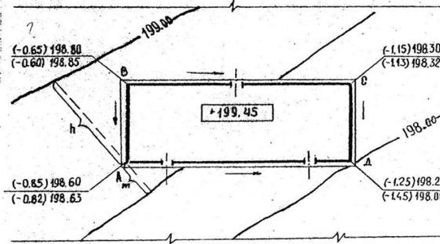
The vertical connection of buildings to a section of terrain, the topography of which is characterized by horizontal lines, is carried out using the interpolation method. To do this, you need to consider the following:
1. If a point (corner of a building) lies on the horizontal, then its elevation is equal to the horizontal elevation.
2. If a point lies between the horizontal lines, then you need to draw a line through this point perpendicular to the adjacent horizontal lines and measure the length of the segment “ m" in mm (distance from the minor horizontal to the point) and distance " d" in mm between horizontal lines.
3. We calculate the black marks of the corners of the building using the formula:
m– distance from the minor horizontal to the corner of the building
d- the distance between the horizontal lines between which the corner of the building is located.
h– height of the section relief.
We find the mark of the finished floor of the first floor as the arithmetic mean value from the obtained marks of the corners of the building.
This value is:
But the floor level of the first floor should be 1-1,200 m higher than the planning level - this is the ground level for residential buildings with a staircase entrance.
H 0 = 198.450+1.00 = 199.450 - this mark of the finished floor of the first floor is conventionally taken as the zero design horizon.
For industrial buildings, the ground surface elevation is taken to be 0.150 m below the workshop floor level, therefore
H 0 = 198.450 + 0.150 = 198.600
Thus, the floor level of the first floor has two marks:
Relative or conditional (0.000) and absolute or geodesic.
The design (red) layout marks for the corners of the building are selected in such a way that the layout slopes in the direction of the longitudinal and transverse axes of the building are in the range of 0.0010+0.0030 and ensure the flow of atmospheric water in the required directions.
Taking into account these slopes and the size of the building, the red marks of its corners can be taken: H a = 198.60; N in = 198.80; N d = 198.20; N c = 198.30 and accordingly determine the relative ground marks of the corners of the building, which should be written in parentheses next to the absolute marks.
To do this, subtract sequentially the angular absolute marks of corners A from the absolute level of the floor of the first floor; IN; WITH; D.
For example: angle A
199,45 – 198,60 = - 0,85
199,45 – 198,63 = - 0,83
Knowing the values of the relative elevations of the ground levels at the corners of the building, pay attention to the number of steps in the porches of external entrances, and for industrial workshops, the installation of inclined planes - ramps.
For an example of performing height reference, see the figure.
 |
 |
Black marks are written below the line.


Determination of the total area of the general plan of the asphalt plant
1. Power unit - 18 m 2
2. Drying drum - 21 m 2
3. Mixing installation - (Table 1)
4. Mineral powder unit - 4 m2
5. Control cabin - 18 m 2
6. Bitumen consumption capacity - 12 m2
7. Installation for bitumen dewatering - 24 m 2
8. Bitumen storage facility - (according to calculations)
9. Platform for draining bitumen - 36 m2
10. Warehouse of stone materials - (according to calculation)
11. Fuel and lubricants warehouse - 108 m 2
12. Fire station - 6 m 2
13. Boiler room - 24 m 2
14. Shower - 24 m2
15. Transformer substation - 36 m 2
16. Rest area - 100 m2
17. Security - 36 m 2
18. Office - 72 m 2
19. Checkpoint - 36 m 2
Table 1. Overall dimensions of equipment for preparing A/B mixtures
Total area of the general plan of the asphalt plant:
S sum. ABZ = S sum. To the jam .;
Where S sum. ABZ - total area of the general plan of the asphalt plant;
S sum. - the total area of all premises located at the asphalt plant;
To the jam. . - coefficient of minimum building density, determined based on the productivity of the asphalt plant.
With productivity up to 50 t/h - To the jam. . = 1.35;
From 50 to 100 t/h - To the jam. = 1.44;
More than 100 - To the jam. . = 1.48.
Dividing the site into squares
On the plan, in horizontal lines (M 1:500 or 1:100), a grid of squares with a side of 10...100 m is drawn, depending on the terrain: a square must contain at least one maximum two horizontal lines (Fig. 1)
Rice. 1. Dividing the site into squares

With very flat terrain, there may be no horizontal lines in the square. The intersection of the sides of the squares form the vertex H, where n is the number of squares adjacent to the vertex. Each square is assigned its own serial number.
Defining black marks
Black marks located between two horizontal lines are determined by interpolation.
For example, the black mark of the top A (H A) Fig. 2:
![]()
where H is the elevation of the lesser horizontal line, m;
h - the excess of one horizontal line over another, m;
l - distance from the horizontal line with a lower elevation to point A, m;
L is the distance between two horizontal lines in plan, m.
The black mark value is written in the lower right corner of the square.
Rice. 2. Determination of black vertex marks by interpolation method

Determination of the average planning level

n is the number of squares.
Determining the design marks of the vertices of the squares
First, you need to graphically determine the distance from the line of zero work to the nearest vertex of the square (Fig. 3).
Rice. 3. Determination of design marks for the tops of the squares

L - side of the square;
L 2 - the minimum distance from the line of zero work to the top of the square.
In the above example, vertex B 2 has the maximum approach to the line of zero work.
Example. Determine the design elevation of the peak B 2, with the side of the square L 1 = 22 m and design slopes i 1 = 2%, i 2 = 2%. The zero work line has an elevation of 22.41 m.
To determine L 2 we make up the proportion:
L 1 = 22 m - 5 cm;
L 2 = x - 0.7 cm,
where 5 cm, 0.7 cm, the actual dimensions L 1 and L 2, determined graphically, on the same scale.
L 2 = 22 × 0.7/5 = 3.08 m.
The elevation of point F, which lies on the line of zero work, has an elevation of 22.41 m. Hence the design elevation of peak B 2:
H B2 = H F + L 2 i 1 ;
N B2 = 22.41 + 3.08 × 0.02 = 22.47;
N B2 = 22,47;
Design slopes are assigned according to the natural terrain and for each side of the design site. i 1, i 2 - accepted according to instructions.
The design elevations of subsequent vertices are calculated using the formula:
H2=H 1 ± L 1 i ,
where H 2 is the design mark of the top of the square being determined;
H 1 - design mark of the top of the adjacent square;
L 1 - side of the square;
i is the design slope in a given direction.
Determination of working marks
Working marks h are calculated as the difference between the design - red (H pr) and black (H 4) marks:
± h = H pr - H 4 .
The design mark is written in the upper right corner, and the working mark in the upper left (Fig. 4).
Rice. 4. The order of recording marks at vertices

Determination of soil volumes within embankment and excavation squares
The volume of soil in the square of the same name is taken equal to the volume of a quadrangular prism, one base of which corresponds to the natural relief, and the other to the planning surface. The volume is calculated as the product of the average working mark (out of four) by the area of the square:

where a is the side of the square, m;
h 1, h 2, h 3, h 4 - working marks, m.
The volume of soil within the transition squares with a relatively small number of them is determined by the formula:

For convenience, the calculation is carried out according to Form A 3-1 (Fig. 5)
Rice. 5. Form A3-1 for calculating the volume of excavation work using a grid of squares
GOST 21.508-93
Group Zh01
INTERSTATE STANDARD
System of design documents for construction
RULES FOR IMPLEMENTATION OF WORKING DOCUMENTATION OF MASTER PLANS OF ENTERPRISES, STRUCTURES AND HOUSING AND CIVIL FACILITIES
System of building design documents. Rules of fulfillment of working documentation of general layouts of enterprises, buildings and civil housing objects
ISS 01.110
OKSTU 0021
Date of introduction 1994-09-01
Preface
1 DEVELOPED by Design Institute No. 2 (PI-2), Central Research and Design-Experimental Institute for Methodology, Organization, Economics and Design Automation (TsNIIproekt), Design Institute Promstroyproekt, Central Research and Design Institute for Urban Planning (TsNIIPgradostroitelstvo)
INTRODUCED by the State Construction Committee of Russia
2 ADOPTED by the Interstate Scientific and Technical Commission for Standardization and Technical Regulation in Construction on November 10, 1993.
The following voted for the adoption of the standard:
State name | Name of the state construction management body |
The Republic of Azerbaijan | State Construction Committee of the Azerbaijan Republic |
Republic of Armenia | State Architecture of the Republic of Armenia |
Republic of Belarus | Gosstroy of the Republic of Belarus |
The Republic of Kazakhstan | Ministry of Construction of the Republic of Kazakhstan |
Republic of Kyrgyzstan | Gosstroy of the Kyrgyz Republic |
Russian Federation | Gosstroy of Russia |
The Republic of Tajikistan | State Construction Committee of the Republic of Tajikistan |
Ministry of Construction and Architecture of Ukraine |
3 ENTERED INTO EFFECT on September 1, 1994 as a state standard of the Russian Federation by Decree of the State Construction Committee of Russia dated April 5, 1994 N 18-31
4 INSTEAD GOST 21.508-85
5 REPUBLICATION. March 2002
An amendment has been made, published in IUS No. 3, 2014
Amendment made by database manufacturer
1 area of use
1 area of use
This standard establishes the composition and rules for the preparation of working documentation for master plans of enterprises, structures and housing and civil facilities* for various purposes (hereinafter referred to as master plans).
_____________________
* Hereinafter, microdistricts, blocks, groups of residential buildings and public buildings are considered as residential and civil objects.
2 Normative references
________________
See note from FSUE "STANDARTINFORM"
This standard uses references to the following standards:
GOST 2.303-68 Unified system of design documentation. Lines
GOST 21.101-93 System of design documentation for construction. Basic requirements for working documentation
GOST 21.110-95 System of design documentation for construction. Rules for fulfilling the specifications of equipment, products and materials
GOST 21.204-93 System of design documentation for construction. Conventional graphic symbols and images of elements of master plans and transport structures
GOST 21.510-83 System of design documentation for construction. Rules for the execution of working drawings of railway tracks
GOST 21.511-83 * System of design documentation for construction. Rules for the execution of working drawings of highways
________________
* The document is not valid on the territory of the Russian Federation. GOST R 21.1701-97 is valid, hereinafter in the text. - Database manufacturer's note.
3 General provisions
3.1 Working documentation of master plans is carried out in accordance with the requirements of this standard, GOST 21.101 and other interrelated standards of the design documentation system for construction (SPDS).
3.2 The working documentation of the master plan includes:
- working drawings of the general plan (the main set of working drawings of the GP brand. When combined in one main set of working drawings of the general plan and transport structures, the main set of working drawings is assigned the GT brand);
- sketch drawings of general types of non-standard products, structures, devices and small architectural forms (hereinafter referred to as sketch drawings of general types of non-standard products);
- statement of requirements for materials - according to GOST 21.110 *;
- statement of volumes of construction and installation work - according to GOST 21.110 *;
________________
* Performed if there are instructions in the contract for the execution of design work.
3.3 The main set of working drawings of the master plan includes:
- general data on working drawings;
- layout plan;
- relief organization plan;
- plan of earth masses;
- consolidated plan of engineering networks;
- territory improvement plan;
- remote elements (fragments, units) in accordance with GOST 21.101 *.
___________________
* Performed with high image saturation.
3.4 Working drawings of the main set are carried out on an engineering topographical plan (except for the drawing of the earth mass plan).
It is allowed to carry out a layout plan, a consolidated plan of utility networks and a plan for landscaping the territory without drawing contour lines of the terrain.
3.5 The contours of the designed buildings and structures are plotted on the plan according to the architectural and construction working drawings, taking the coordination axes of the buildings and structures aligned with the internal edges of the walls.
When the distance from the outer edge of the wall of a building or structure to the coordination axis on the image scale exceeds the thickness of the contour line, the latter is removed from the coordination axis by the appropriate distance () in accordance with Figure 1.
3.6 Working drawing plans place the long side of the conditional border of the territory along the long side of the sheet, while the northern part of the territory should be at the top. North orientation deviation is allowed within 90° to the left or right. Plans located on different sheets are carried out with the same orientation.
3.7 If the image saturation is low, it is allowed to combine several different plans into one and assign it the appropriate name.
Example - “Layout plan and relief organization plan”, “Relief and earth mass organization plan”.
3.8 If the images of the territory improvement plan are very rich, it is allowed to carry out several plans by type of work, assigning each plan a corresponding name.
Example - “Landscaping plan”, “Plan for the location of small architectural forms”, “Plan of driveways, sidewalks, paths and platforms”.
3.9 It is allowed to divide the plan into several sections, placing them on separate sheets. In this case, on each sheet where a section of the plan is shown, a diagram of the whole plan is given, broken down into sections, the numbers of the sheets on which they are located are indicated, and the section shown on this sheet is indicated by hatching.
3.10 Working drawings of general plans may be released in stages - developments as the corresponding working drawings of buildings, structures of the designed enterprise or housing and civil facility are completed.
In this case, each development is drawn up as of a certain date with the corresponding additions to the working drawings. The next development is not considered and is not formalized as a change.
Developments are assigned serial numbers.
3.11 During the next development, the main inscription is supplemented on the left with columns 10-13 according to GOST 21.101 in accordance with Figure 2.
A list of drawing developments is placed above the main inscription: for the alignment plan, plans for organizing the relief, earth masses and landscaping of the territory - according to Form 1, for the consolidated plan of utility networks - according to Form 2.
Examples of drawing up development sheets are given in Appendices A and B.
3.12 Images on the master plan drawings are made with lines in accordance with GOST 2.303:
- solid thick main ones - the contours of the designed buildings and structures (except for buildings and structures on the earth mass plan), the “red” line, the design contours with marks that are multiples of 0.50 and 1.00 m;
- a thin dashed line - a line of “zero” work and a break in the design relief;
A very thick dash-dotted line with two dots - the conventional boundary of the territory of the designed enterprise, building, structure;
- solid thin - designed buildings, structures on the plan of earth masses and all other elements of the master plan.
3.13 Plans of working drawings are made on a scale of 1:500 or 1:1000, fragments of plans - on a scale of 1:200, nodes - on a scale of 1:20.
It is allowed to carry out plans on a scale of 1:2000, components - on a scale of 1:10.
The scale of the image is indicated in the title block after the name of the image.
If several images are placed on a sheet, made at different scales, then the scales indicate the field of the drawing under the name of each image.
3.14 The system of elevations adopted in the working drawings of general plans must correspond to the system of elevations adopted on the engineering topographic plan.
3.15 Dimensions, coordinates and elevations are indicated in meters with an accuracy of two decimal places.
3.16 The magnitude of the angles is indicated in degrees with an accuracy of one minute, and, if necessary, up to one second.
3.17 The magnitude of the slopes is indicated in ppm without indicating the unit of measurement.
The steepness of slopes is indicated as the ratio of the unit height of the slope to the horizontal position.
3.18 Basic graphic symbols and images of elements of the master plan and transport structures are adopted in accordance with GOST 21.204.
Small architectural forms (for example, gazebos, canopies, fountains, sculptures, pergolas, etc.) and other structures, products, devices (for example, benches, urns, etc.) are carried out in a simplified manner on the drawing scale or with conventional graphic symbols.
3.19 When making working drawings of the master plan, the serial numbers of buildings and structures (including fences, retaining walls, overpasses, galleries, tunnels) are taken, as a rule, according to the master plan developed at the previous stages of design.
Drainage structures (ditches, gutters, pipes) are assigned independent serial numbers.
When combining master plan drawings and transport structures into one main set, railway tracks and roads are assigned independent serial numbers.
It is allowed not to assign serial numbers to roads and drainage structures. In this case, their coordinates are indicated on the plan.
3.20 On the plans (except for the plan of earth masses), an explication of buildings and structures is provided in Form 3 (for master plans of industrial enterprises) or a list of residential and public buildings and structures in Form 4 (for master plans of housing and civil facilities). It is allowed to provide an explication or list of buildings and structures on a sheet of general data based on working drawings.
3.21 In the explication columns of buildings and structures indicate:
- in the “Name” column - the name of the building, structure;
- in the column “Coordinates of the grid square” - the coordinates of the lower left corner of the square of the construction geodetic grid, within which its number is indicated on the image of the building and structure (if necessary).
An example of the design of explications of buildings and structures is given in Appendix B.
3.22 In the columns of the statement of residential and public buildings and structures indicate:
- in the column “Number on the plan” - the number of the building, structure;
- in the column “Name and designation” - the name of the building, structure, indicating the designation of an individual or standard project, a project according to the catalog;
- in the remaining columns - data in accordance with their names.
An example of registering residential and public buildings and structures is given in Appendix D.
4 General data on working drawings
General data on working drawings is carried out in accordance with GOST 21.101, taking into account the following changes and additions:
- the list of specifications is not fulfilled;
- in general instructions, in addition to the information provided by GOST 21.101, the designations and names of documents that are the basis for the development of working drawings of the general plan (for example, materials of engineering geodetic and engineering geological surveys), the adopted system of coordinates and elevations are given.
5 Layout plan
5.1 On the layout plan (plan of the location of buildings and structures) the following is drawn and indicated:
a) a construction geodetic grid or a subdivision base replacing it, and for residential and civil facilities, in addition, an urban geodetic grid, which must cover the entire plan;
b) the “red” line separating the territory of the highway, street, driveway and square from the territory intended for development;
c) fences with gates and wickets or a conventional boundary of the territory. If the fence coincides with the “red” line or with the conditional border of the territory, then only the fence is applied with the corresponding explanation on the drawing;
d) wells and pits for engineering-geological surveys, not indicated on the engineering-topographic plan;
e) buildings and structures, incl. communication (overpasses, tunnels);
f) production and storage sites;
g) highways and paved areas;
i) railway tracks;
j) landscaping elements (sidewalks, sports and recreational areas);
k) elements and structures of the planning relief (slopes, retaining walls, ramps);
l) drainage structures;
m) north direction indicator with an arrow with the letter “C” at the tip (in the upper left corner of the sheet).
5.2 The layout plan is carried out with coordinate or dimensional reference.
5.3 The construction geodetic grid is applied to the entire layout plan in the form of squares with sides of 10 cm.
The origin of coordinates is taken in the lower left corner of the sheet.
The axes of the construction geodetic grid are designated by Arabic numerals, corresponding to the number of hundreds of meters from the origin, and by capital letters of the Russian alphabet.
Examples
1 0A (origin); 1A; 2A; 3A - horizontal axes;
2 0B (origin); 1B; 2B; 3B - vertical axes.
In drawings made at a scale of 1:500, the axes of the construction geodetic grid are designated in accordance with the examples given.
Examples
1 0A (origin); 0A+50; 1A; 1A+50; 2A; 2A+50 - horizontal axes;
2 0B (origin); 0B+50; 1B; 1B+50; 2B; 2B+50 - vertical axes.
It is allowed, if necessary, to use negative values of the axes of the construction geodetic grid.
Examples
1 0A (origin); 0A-50; -1A; -1A-50; -2A; -2A-50 - horizontal axes;
2 0B (origin); 0B-50; -1B; -1B-50; -2B; -2B-50 - vertical axes.
When expanding, reconstructing and technically re-equipping existing enterprises, it is allowed to retain the previously accepted designations of the axes of the construction geodetic grid.
5.4 Dimensional reference is carried out from the alignment basis.
The alignment basis can be any straight line passing through two points fixed on the ground, which are designated by capital letters of the Russian alphabet.
Example - A; B.
5.5 Buildings and structures on the plan are drawn to the scale of the drawing, indicating the openings of gates and doors, extreme axes and, if necessary, the coordinates of the gate axes or linking the gates to the coordination axes of the building.
5.6 Inside the outline of the building (structure) indicate:
a) number of the building or structure in the lower right corner;
b) an absolute elevation corresponding to the conventional zero elevation adopted in the construction working drawings of a building or structure, which is placed on a leader line shelf and marked with a sign (for residential and civil facilities - if necessary).
5.7 On the outline of a building or structure indicate:
a) coordinates of the intersection points of the coordination axes of a building, structure in its two opposite corners, and in case of a complex configuration of a building, structure or its location not parallel to the axes of the building geodetic grid - in all corners, for centric structures - coordinates of the center and one characteristic point, as well as diameter, for linear structures - axis coordinate or coordinates of the beginning and end of individual sections;
b) dimensional reference of the coordination axes of the building, structure to the alignment basis and the dimensions of the building, structure between the axes in the absence of a construction geodetic grid;
c) designation of the coordination axes of a building or structure at coordinated points.
5.8 Around the outline of the building, structures show blind areas and entrance ramps, external stairs and platforms at the entrances.
5.9 On the alignment plan for the part of the roads, the following shall be drawn and indicated:
a) crossing railway tracks;
b) transport interchanges;
c) coordinates or references of highway axes and, if necessary, their numbers;
d) width of roads;
e) radii of curves along the edge of the carriageway of highways at the places of their mutual intersection and adjacency;
f) slopes of embankments and excavations (if necessary).
5.10 In the absence of the main set of working drawings of highways (grade AD), the alignment plan is carried out taking into account the requirements of GOST 21.511.
5.11 On the alignment plan in part of the railway tracks the following is drawn and indicated:
a) track number;
b) turnouts;
c) stops;
d) slopes of embankments and excavations (if necessary).
5.12 In the absence of the main set of working drawings of railway tracks (PZh brand), the alignment plan is carried out taking into account the requirements of GOST 21.510. At the same time, the bottom marks and the magnitude of the slopes of drainage structures and slope indicators do not indicate.
5.13 A list of drainage structures according to Form 5 is provided on the layout plan.
An example of drawing up a statement of drainage structures is given in Appendix D.
5.14 An example of drawing up a layout plan of a production enterprise with coordinate reference is given in Appendix E.
6 Relief organization plan
6.1 The relief organization plan is carried out on the basis of a layout plan without indicating and drawing the coordination axes of buildings and structures, coordinates, dimensions and dimensional references.
6.2 On the relief organization plan the following is drawn and indicated:
a) absolute marks inside the contour of buildings and structures, in accordance with 5.6 (listing b);
b) design marks and grade indicators along the “red” lines;
c) design contours or design marks of planning reference points indicating the direction of the slope of the design relief;
d) marks of the bottom and top of slopes, stairs, retaining walls, ramps;
e) bottom marks in places of fractures of the longitudinal profile, direction and magnitude of slopes of drainage structures;
f) rainwater inlet gratings at low points of the design topography with marks for the top of the gratings;
g) design planning marks and actual terrain marks along the outer contour of the blind area in the corners of buildings and structures or, in the absence of a blind area, the indicated marks at the intersection of the outer edges of the walls with the relief in the corners of buildings and structures - in the form of a fraction with the design mark in the numerator and actual - in the denominator;
i) design planning marks and actual terrain marks (if necessary) along the top of sites for various purposes at the intersection of their edges with the relief at the corners and at characteristic points;
j) fracture lines of the design relief - when implementing the plan at the design elevations of the planning reference points;
k) the direction of the slope of the design relief with berg strokes - when executing the plan in design contours and arrows - when executing the plan in design elevations.
6.3 On the relief organization plan, in terms of highways, the following is drawn and indicated:
a) design contours - when implementing the plan in design contours;
b) the contours of the transverse profile of highways - when implementing the plan at design elevations;
c) fracture points of the longitudinal profile with design marks;
d) slope indicators along the axis of the carriageway of roads;
e) drainage structures - ditches, trays with bottom marks in places of fractures of the longitudinal profile and the magnitude of the slopes of the bottom of the structures;
f) rainwater inlet gratings at low points of the longitudinal profile with marks on the top of the gratings.
6.4 On the relief organization plan, in part of the railway tracks, the following is drawn and indicated:
a) inclination indicators;
b) marks of the bottom of drainage structures in places where the longitudinal profile breaks and the values of the slopes of the bottom of the structures.
6.5 The relief organization plan should, as a rule, be carried out in the design contours.
6.6 When implementing a relief organization plan in design contours, they are carried out with a relief section every 0.10 or 0.20 m throughout the entire planned territory (ground surface, roads, sites). It is allowed in areas with a uniform slope of the relief to draw design horizontal lines with a relief section every 0.50 m.
Markings of design contours are inscribed from the side of increasing relief. Design contour elevations that are multiples of 1.00 m are indicated in full; intermediate elevations are given in the form of an integer corresponding to two decimal places.
6.7 When implementing a relief organization plan at the design elevations of the planning reference points, the following are usually taken as reference points:
a) corners of buildings, structures and sites;
b) high and low points of the design relief;
c) intersection of highway axes;
d) turning points of the longitudinal profile of roads and railways.
6.8 On the relief organization plan indicate the design marks of entry and exit along the bottom of pipes and intersleeper trays, as well as marks of turning points along the bottom of drainage ditches and trays. On the shelf of the leader line of drainage ditches and trays their abbreviated name is given.
Examples
1 D.l. - bottom of the tray;
2 D.k. - the bottom of the ditch.
6.9 Examples of drawing up relief organization plans in design contours and design elevations of planning reference points are given in Appendices G and I, respectively.
7 Plan of earth masses
7.1 Calculation of volumes of earth masses is carried out, as a rule, using the square method.
It is allowed to carry out the earth mass plan using other methods. The content and form of the plan are determined by the method of calculating the volume of earth masses and the conditions of work.
7.2 On the plan of earth masses the following is applied and indicated:
a) a construction geodetic grid or a subdivision base replacing it;
b) a grid of squares for calculating the volume of earth masses with design, actual and working marks in the corners of the squares, a line of “zero” work highlighting the area of excavations by hatching at an angle of 45° to the base of the grid and indicating the volume of earth masses within each square or other figure, formed by the contour of the layout;
c) buildings and structures;
d) fencing or conditional boundary of the territory;
e) slopes, retaining walls.
7.3 The grid of squares, as a rule, is included in the construction geodetic grid, taking the side of the square equal to 20 m. It is allowed to link the grid of squares to the “red” line or to the alignment basis, as well as the use of a grid of squares with sides equal to 10, 25, 40 or 50 m, depending on the nature of the relief and ensuring the required accuracy in calculating the volume of earth masses.
It is allowed, depending on the configuration of the planned territory, to use figures other than a square to calculate the volume of earth masses. In these cases, the dimensions of the figures are indicated in the drawing.
7.4 Under each column of squares of the earth mass plan, a table is given in Form 6, in the corresponding columns of which the total volumes of embankment and excavation are indicated in the column of squares, and in the lines of total volumes on the right - the total volumes of embankment and excavation throughout the entire planned territory.
7.5 In the event of occurrence of soils to be removed within the planned territory (fertile soil layer, peat, soil unsuitable as the foundation of buildings, structures), before developing an earth mass plan for the entire territory, a soil removal plan is carried out within the boundaries of the contour of the soils to be removed , designing it similarly to the plan of earth masses.
On the soil removal plan, the design marks are taken to be the marks of the bottom of the soil to be removed, which are considered as actual marks during the subsequent implementation of the earth mass plan.
If there are heterogeneous soils on the construction site, it is allowed to carry out plans for each type of soil, assigning the corresponding name to the drawing.
Examples
1 "Plan of earth masses. Removal of construction waste";
2 "Plan of earth masses. Development of rocky soils."
If the soil to be removed lies in a layer of the same thickness, the soil removal plan may not be carried out. In this case, the actual marks for the plan of earth masses are taken to be the marks of the bottom of the soil to be removed, and the calculated volume of soil to be removed is entered into the corresponding lines and columns of the statement in Form 7.
7.6 On the plan of earth masses the following is given:
a) statement of volumes of earth masses in form 7;
b) text instructions on the need to adjust working marks in places where lawns are installed, troughs for roads, platforms and the superstructure of railway tracks.
7.7 Examples of drawing up a plan of earth masses and a statement of volumes of earth masses are given in Appendices K and L, respectively. The examples were developed for the case of performing vertical planning before the start of construction of buildings and structures.
8 Master plan of utility networks
8.1 The master plan of utility networks is carried out on the basis of a layout plan, but without absolute marks of buildings, structures, gate references and designations of the coordination axes of buildings and structures.
If necessary, the external contours of the base of the foundations of designed and existing buildings and structures are drawn on the plan.
On images of roads and railways, only the coordinates or references of their axes are indicated.
Utility networks are carried out using conventional graphic symbols in accordance with GOST 21.204.
8.2 On the summary plan of utility networks, the following is plotted and indicated:
a) communication structures for laying networks;
b) underground, ground and overhead networks;
c) rainwater gratings, supports and racks of communication structures.
8.3 Utility networks are drawn according to the working drawings of the corresponding main sets with a coordinate or linear reference to the network axis at each characteristic section, with images of compensators, niches, wells, chambers and indicating their designations.
8.4 An example of the design of a consolidated plan for utility networks is given in Appendix M.
9 Territory improvement plan
9.1 The territory improvement plan is carried out on the basis of a layout plan without indicating coordination axes, coordinates and dimensional references, absolute elevations of buildings and structures.
On images of roads and railways, if necessary, only the coordinates or references of their axes are indicated.
9.2 On the territory improvement plan the following shall be drawn and indicated:
a) sidewalks, paths and their width;
b) sites for various purposes and their sizes;
c) small architectural forms and portable products of recreation areas;
d) trees, shrubs, flower beds, lawns.
9.3 Landscaping elements are tied to the outer edges of the walls of buildings, structures, “red” lines, roads or railway tracks.
For row planting of trees and shrubs, the row dimensions are given.
9.4 With a complex configuration of paths, when trees and shrubs are located in loose groups, it is allowed, instead of dimensional reference, to apply an auxiliary grid of squares with sides equal to 5-10 m in areas where they are located, linking it to the construction geodetic grid, alignment base, buildings, structures, automobile roads and railways.
9.5 Landscaping elements are assigned positional designations. Positional designations of small architectural forms and portable products are indicated on leader lines in circles with a diameter of 6 mm. The designation of landscaping elements is indicated on the leader line in circles with a diameter of 8-12 mm in the form of a fraction: in the numerator - the positional designation of the species or type of planting, in the denominator - their number or area (for flower beds).
9.6 On the territory improvement plan the following is given:
a) a statement of small architectural forms and portable products according to Form 8, an example of which is given in Appendix H;
b) a list of landscaping elements in Form 9, an example of which is given in Appendix P;
c) a list of sidewalks, paths and platforms in Form 10, an example of which is given in Appendix P; (Figure P.1);
d) sections, sections and nodes of sidewalks, paths and platforms. An example of the design of sections of sidewalks, paths and platforms is given in Appendix C;
e) list of highways, entrances and passages in accordance with GOST 21.511 (form 1) - for housing and civil facilities, an example of which is given in Appendix P (Figure P.2);
f) relevant textual instructions, for example, on the conditions for planting trees and shrubs, arranging flower beds and lawns, etc.
9.7 It is allowed to place the statements specified in 9.6 on the general data sheet.
9.8 Examples of drawing up a landscaping plan carried out by type of work are given: in Appendix T - “Landscaping Plan”; in Appendix U - “Plan for the location of small architectural forms and portable products”; in Appendix F - “Plan of driveways, sidewalks, paths, platforms.”
10 Sketch drawings of general types of non-standard products
10.1 The sketch drawing defines the design of a non-standard product, contains a simplified image, basic parameters and technical requirements for the product in the amount of initial data (building) necessary for the development of design documentation.
10.2 Sketch drawings are developed for products (structures, devices) in the absence of mass production, standard drawings (documentation for mass use), standards or other documents for these products.
10.3 A separate sketch drawing is made for each non-standard product. An exception is a group of products that have common design features, for which it is allowed to perform a group sketch drawing.
10.4 The sketch drawing is assigned an independent designation, consisting of the designation of the main set of working drawings in accordance with GOST 21.101, through the code point H and the serial number of the sketch drawing.
Example - 2345-11-GP.N1; 2345-11-GP.N2.
Note - distance from the inner edge of the contour of a building or structure to the coordination axis
Picture 1
Figure 2
Form 1
Drawing development sheet
Development sheet for the master plan of utility networks
Form 3
Explication of buildings and structures
List of residential and public buildings and structures
List of drainage structures
To the plan of earth masses
graph width; - number of graphs
Note - The width and number of columns and their number must correspond to the grid of squares of the earth mass plan.
Form 7
List of volumes of earth masses
Notes
2 The second line of the table head is provided for the name of the territory for which the data is provided.
Example - “Pre-factory territory”, “Residential development”. The number of allocated parts of the territory is specified according to the design data.
List of small architectural forms and portable products
Form 9
List of landscaping elements
Form 10
List of sidewalks, paths and platforms
Appendix A (for reference). An example of a drawing development sheet
Appendix A
(informative)
An example of a drawing development sheet
Appendix B (for reference). An example of drawing up a development sheet for a consolidated plan for utility networks
Appendix B
(informative)
An example of drawing up a development sheet for a consolidated plan for utility networks
Note - An example of the statement is given for the coordinate reference of networks.
Appendix B (for reference). Example of design of explication of buildings and structures
Appendix B
(informative)
Example of design of explication of buildings and structures
Appendix D (for reference) Example of registration of a statement of residential and public buildings and structures
Appendix E (for reference) Example of drawing up a statement of drainage facilities
Appendix E (for reference) Example of a layout plan
Appendix G (for reference) Example of drawing up a relief organization plan in design contours
Appendix I (for reference) Example of drawing up a relief organization plan in design marks
Appendix K (informative) Example of drawing up a plan of earth masses
Appendix L (for reference) Example of preparing a list of volumes of earth masses
Soil name | Quantity, m | Note |
|||
Factory area | Pre-factory territory | ||||
Embankment (+) | Notch (-) | Embankment (+) | Notch (-) | ||
1 Territory planning soil | |||||
2 Displaced soil, | |||||
incl. with the device: | |||||
a) underground parts of buildings and structures | |||||
b) road surfaces | |||||
c) railway ways | |||||
d) underground networks | |||||
e) drainage structures | |||||
e) fertile soil in green areas | |||||
3 Soil for constructing high floors of buildings and embankments of structures | |||||
4 Compaction correction | Eng.-geol. refinement |
||||
Total suitable soil | |||||
5 Lack of suitable soil | |||||
6 Soil that is not suitable for embankment of foundations of buildings and structures and must be removed from the territory (peat) | |||||
7 Fertile soil, total, including: | |||||
a) used for landscaping | |||||
b) excess fertile soil (land reclamation) | |||||
8 Total processed soil | |||||
*Taking into account preliminary cutting of fertile soil. |
|||||
(Amendment. IUS No. 3-2014).
Appendix M (for reference) Example of a master plan for utility networks
Appendix N (for reference) Example of registration of a list of small architectural forms and portable products
Appendix P (for reference) Example of registration of a list of landscaping elements
Appendix P (for reference) Example of drawing up a list of sidewalks, paths and platforms; An example of a list of roads, entrances and passages
Appendix P
(informative)
An example of a list of sidewalks, paths and platforms
Figure P.1
An example of a list of roads, entrances and passages
Figure P.2
Appendix C (for reference) Example of design of sections of sidewalks, paths and platforms
Appendix T (for reference). Example of a landscaping plan
Appendix T
(informative)
Example of a landscaping plan
Appendix U (for reference) Example of a layout plan for small architectural forms and portable products
Appendix F (for reference) Example of design of a plan of passages, sidewalks, paths, platforms
NOTE FSUE "STANDARTINFORM"
Electronic document text
prepared by Kodeks JSC and verified against:
official publication
M.: Standartinform, 2008
(as of March 2008)
Revision of the document taking into account
changes and additions prepared
JSC "Kodeks"
FEDERAL AGENCY FOR SPECIAL CONSTRUCTION
MILITARY TECHNICAL UNIVERSITY
Calculation and graphic work
by discipline
Technology of Construction Processes.
Completed by: senior Usov D.I.
Check docent
Semenov V.V.
Balashikha 2012
1.1. Determination of black, red and working marks.
1.2. Construction of a line of zero works.
1.3. Determination of soil volumes in basic figures.
1.4. Determination of soil volumes in site slopes.
1.5. Balance sheet of earth masses.
1.6. Determining the volume of a straight-shaped pit by its plan dimensions along the bottom.
1.7. Drawing up a plan for the distribution of earth masses, determining the average distance of movement.
2. Development of work production technology.
2.1.Selection of machines for leveling work.
2.2.Choice of an excavator for excavation excavation.
2.3. Selection of dump trucks for transporting soil.
2.4 Selection of dump trucks for transporting soil from the quarry to the embankment
1.5. Determination of the composition and number of auxiliary machines.
Calculation of labor costs and creation of a work schedule.
3.1Calculation of labor costs for the production of zero-cycle work.
3.2 Construction of a schedule for performing earthworks.
Calculation of work volumes at a construction site.
Determination of black, red and working marks.
Calculations are carried out using the method of tetrahedral or triangular prisms. A planning grid is applied to the site plan in horizontal lines, which divides the sites into squares and rectangles. The size of the square is determined depending on the terrain. We take the side size of a square to be 100 m. To simplify calculations, it is desirable that the squares (rectangles) are the same in size and their number is not large. In the corners of the planning grid (the intersection of the sides of the squares) we set the actual (black) N h, design (red) N cr And working marks h p.
Black mark(terrain elevation) in the corners of the planning grid is found by interpolating horizontally using the formula:
where Г 1 and Г 2 – height of horizontal marks;
x is the distance to one of the horizontal lines
planning grid;
L – distance between horizontal lines.
Let's find the black marks in accordance with our option (Fig. 1.1.1)
11 =152+(152-152,5)*8/18=151,78
12 =152,5+(152-152,5)*34/53=152,18
13 =153+(152,5-153)*45/54=152,58
14 =153+(152,2-153)*4/54=152,96
15 =153,5+(153-153,5)*27/58=153,27
16 =153,5+(153,5-153)*19/58=153,66
21 =153+(152,5-153)*22/35=152,69
22 =153+(152,5-153)*5/26=152,90
23 =153,5+(153 -153,5)*5/21=153,38
24 =154+(153,5-154)*5/22=153,89
25 =153,5+(154-153,5)*17/24=153,79
26 =153,5+(154-153,5)*4/29=153,57
31 =153,5+(153-153,5)*13,3/33=153,30
32 =154+(153,5-154)*22/28=153,60
33 =153,5+(154-153,5)*24/31=153,89
34 =153+(153,5-153)*26,5/33=153,40
36 =152,5+(153-152,5)*17/27=152,81
41 =153,5+(153,5-153)*27,5/32=153,93
42 =153,5+(154 -153,5)*38/55,5=153,84
43 =153+(153,5-153)*45/48=153,47
44 =153+(153,5-153)*4/48=153,04
46 =152,5+(153-152,5)*24/21=151,93
Magnitude red marks depends on the type of layout, which in turn is determined by the terrain conditions, economic considerations and can be as follows: under a natural slope, specified elevation, zero balance.
When planning for a given slope, the site plan indicates the elevation of the design plane at some point on the site, as well as the magnitude and direction of the slope. In this case, the red marks in the corners of the squares are determined by the formula
Where N -mark of a given point, m, for the initial value we find N avg; l -distance from a given point to the top of the square (in the direction of the slope), m; i -slope value in hundredths or thousandths. In the formula the sign " plus " is applied if the vertex lies higher relative to the given point, and " minus " - when it is located below a given point. If the direction of the slope (in our case) is parallel to the side of the square, all the vertices of the squares located on a straight line perpendicular to the direction of the slope will have the same red mark.
To find Нср we use the formula
The sum of the black vertex marks common to one, two, four squares, respectively.
151,78+153,66+151,93+153,93=611,3.
153,30+152,69+152,18+152,58+152,96+153,27+153,57+152,81+
152,5+153,04+153,47+153,84=1836,21.
152,6+152,9+153,38+153,89+153,79+153+153,40+153,89=1227,85
N av =(611.3+2*1836.21+4*1227.85)/(4*15)=453.25
We determine the red marks of intermediate vertices using the formula indicated above
153,25-100*0,003=152,95
152,95-100*0,003=152,65
153,25+100*0,003=153,55
153,55+100*0,003=153,85
153,85+100*0,003=154,15
Working marks are defined as the difference between black and red marks:
Calculations to determine the working mark are carried out in one step (easy to do with a microcalculator), so we will immediately record their values in diagram 1
If the black marks are larger than the red ones, then the workers have a “+” sign and correspond to the notch; if the red marks are larger than the black ones, then the working marks have a “-” sign and correspond to the embankment.
In accordance with the coordinates of the corners of the site in the assignment for the course work, we select the required area based on the area plan with contour lines and a coordinate grid.
As a result, we obtain the terrain areas shown in Figure 1.1
Figure 1.1 - Given terrain plan
To determine the volume of excavation work, it is necessary to determine the black and red marks at the nodes of the coordinate grid.
According to the assignment, the horizontal drop is 1 m. So, in Figure 1.2 X 2 =1. Meaning l And l 1 and also L determined with a ruler and based on the selected scale. As a result we get:
Then the black markHch will be:
Thus, we find all the black marks in all grid nodes and write them in the lower right corner of the node, with an accuracy of 0.01 m.


Drawing. 1.2 a, b - Scheme for determining black marks
The red marks are the marks of the planning plane. They are determined, like black ones, at the nodes of a coordinate grid drawn on the terrain plan.
In order to reduce the volume of excavation work, the slope of the planning plane must be coordinated with the direction of the natural slope. terrain. Layout planes and their slope can be specified or required to be established taking into account certain conditions.
The determination of red marks is carried out subject to the position of the planning plane, the condition of zero balance of earth masses; The slope of the planning plane is specified. With zero balance of earth masses on the site, the volume of the excavation is equal to the volume of the embankment. In this case, if the planning plane is horizontal ( i= 0.00), then the red marks of all points on the site are equal to the weighted average black mark N Wed.v. . This mark is determined using method of static moments relative to the zero horizon and is used in cases where the site is divided into elementary sections of various size configurations. It is found by the formula

Where h kr - average black mark within a separate elementary figure of the site (determined by the known black marks of its corner points);
e - frequency coefficient i-th figure, which is proportional to the plane
spare the elementary figure.
Method of arithmetic mean values of marks is a special case of the previous one, when the elementary sections have the same configuration and size. In this case, the above formula will take the form

Where P-number of elementary figures.
In construction practice, site planning on a horizontal plane occurs in rare cases, since due to the need to drain atmospheric water, the planning plane is given a slope of at least 0.002. When the terrain is calm, use method of squares, having less labor intensity of calculations, the planning area is divided into a grid of squares and the average mark N avg, determined by the formula

In this case, the resulting weighted average mark N av. is equal to the red mark at the center of gravity of the array. It can be tentatively assumed that the center of gravity of the array coincides with the center of gravity of the horizontal projection of the area.
We outline the line of the greatest slope of the projected plane, which is drawn perpendicular to most horizontal lines and directed in the direction of the fall of the latter.
From the found weighted average mark, we lower the perpendicular to the line of the largest slope. This perpendicular defines a line of equal reference marks. From the corner extreme points of our grid of squares we lower the perpendiculars to the line of the largest slope. We determine the red marks of these points:
Where N Wed.v. - red mark defining the planning plane;
X- distance in meters from the projection of the design point to the projection of the nodal point along the line of the largest slope;
i- terrain slope.
Signs (+) or (-) are placed depending on the position of the nodal point relative to the line of equal marks. By interpolation, according to the above method, we determine the remaining red marks of all squares. Red marks are calculated to the nearest 0.01 m and are written in red above the black marks.
In our example, the sequence for determining red marks is as follows:
1) Determine the weighted average mark.
First we find the average black mark of each i- th square:
2) Set the weighted average elevation of the entire section:

3) Through a point H avg. we set the line of the largest slope, which we draw perpendicular to the horizontal lines (Figure 1.3).
4) From the corner points of the squares of the coordinate grid, we lower the perpendiculars to the line of the largest slope and determine from the point H cv to the desired point of the node (using the example of node A, Figure 1.3).

Figure 1.3 - Definition of red marks
5) If the slope is not specified according to the assignment, then we determine it using the following method (Figure 1.4).

Figure 1.4 - Profile of the area along the line of the greatest slope
Finding the site profile. In accordance with the profile of the site, we determine the slope:
Where i- slope of the planning plane;
H 1 and H 2 - values of black marks at a point X intersections.
l- a distance equal to the length of the segment between the extreme values of the black marks based on the profile of the site;
6) In accordance with the initial data (see Figure 1.4), the slope will be

7) Determine the value of the red mark in corner A:
8) Similarly, we find the values of the red marks in other nodes.
Determination of working marks and establishment of the contour of earth masses
Working marks are determined at all nodes of the coordinate grid by subtracting the black mark from the red mark. In the excavation area the working mark will be negative, and in the embankment area it will be positive.
The resulting working marks with their signs are recorded on the site plan to the left of the corresponding red marks. The contour of the earth masses in the course work covers excavations, embankments when planning the site, slopes of embankments and excavations at the boundaries of the site, a pit for a building and trenches for communications (Figure 1.5).
At the boundaries of the embankment with the excavation there is a line of zero work, the position of which is determined by the known adjacent working marks of the embankment and excavation (i.e., by marks with different signs).
The location of the slope line is determined along the contour of the site at the coordinate grid nodes. It is equal to the product of the working mark in a given node by the steepness of the slope:
Where m- slope steepness. (depending on the type of soil)

Figure 1.5 -Working marks, contour of earth masses and line of zero works