Hydroarrow operating principle, purpose and calculations. Purpose and principle of operation of a hydraulic arrow for heating. On what principle does the hydraulic arrow work?
Read also
If you think that only a specialist with a technical background can understand the design of a hydraulic arrow, then you are mistaken. In this article we will explain in an accessible form appointment basic principles of its functioning and rational calculation methods.
Hydroarrow(synonyms: hydrodynamic thermal separator, hydraulic separator, and in Russian - anuloid) is a device designed to equalize both temperature and pressure in the heating system. To put it simply, we reset the supply pressure and return pressure.
Main functions
- increasing energy efficiency by increasing the efficiency of the boiler and pumps, which leads to lower fuel costs;
- ensuring stable operation of the system;
- eliminating the hydrodynamic impact of some circuits on the total energy balance of the entire heating system (to separate the radiator heating circuit and the heating boiler).
What forms of hydraulic arrow exist?
A hydrodynamic thermal separator is a vertical volumetric container, which in cross section can be in the form of a circle or square
Taking into account the theory of hydraulics, hydraulic arrow round shape performs better than its counterpart square shape. 
However, the second option fits optimally into the interior. Before you study hydraulic arrow principle, pay attention to the diagram below.

Pumps Gp And Gs create flow in the first and second circuits, respectively. Thanks to the operation of the pumps, the coolant circulates in the circuits and mixes it in the hydraulic arrow.
Option 1. If Gp =Gs the coolant moves from one circuit to the second, then the temperature in the primary circuit and in the secondary the same.
Option 2. If Gp >Gs the coolant moves in the hydraulic arrow from top to bottom, while the temperature in the supply circuit will be the same both in the primary circuit and in the secondary circuit.
Option 3. If Gp <Gs the coolant moves from bottom to top in the hydraulic arrow, now The return line temperature is the same in both the primary and secondary circuits.
Based on the above, it follows that the Hydroarrow must be selected according to maximum flow in any of the heating circuits.

Thus, a hydrodynamic thermal separator is needed when there is a heating system that is complex in design, consisting of many circuits.

A little about the numbers...

There are several methods by which calculation of hydraulic arrows.
The diameter of the hydraulic separator is determined by the following formula:

where D is the diameter of the hydraulic needle, Q is the water flow rate (m3/s), π is a constant equal to 3.14, and V is the vertical flow velocity (m/s). It should be noted that the economically advantageous speed is 0.1 m/s.
The numerical values of the diameters of the nozzles included in the hydraulic arrow are also calculated using the above formula. The difference is that the speed in this case is 0.7-1.2 m/s, and the flow rate (Q) is calculated for each carrier separately.

The volume of the hydraulic arrow affects the quality of the system’s functioning and helps regulate temperature fluctuations. The effective volume of a heating system with a hydraulic arrow is 100-300 liters.
For determining optimal sizes The hydrodynamic thermal separator uses a method of three diameters and alternating pipes.

We calculate using the formula:
 where π is a constant equal to 3.14, P is the boiler power (in J), C is the heat capacity of the coolant (for water 4.183 kJ/(kg °C), W is the speed at which the coolant moves in the hydraulic arrow (m/s) , ΔT is the temperature difference between the heat supply points from the boiler (upper and lower).
(3 d) - indicator calculated by trial and error.
Only pros and no cons
Based on the above, the following advantages of using hydraulic arrows can be identified:
- optimization of operation and increase in the service life of boiler equipment;
- system stability;
- simplification of selection;
- the ability to control the temperature gradient;
- if necessary, you can change the temperature in any of the circuits;
- ease of use;
- high economic efficiency.
In order not to worry about the uninterrupted operation of the heating system, to minimize heat loss, to increase the efficiency of the boiler, to maintain the temperature in the entire house at the most comfortable and stable level, a hydraulic arrow is needed. This container stabilizes the distribution of coolant throughout the entire area of the room and extends its service life. heating system, as it prevents the occurrence of hydraulic shocks.
Why do they trust us with the calculation and installation of hydraulic arrows?
You should not install the hydraulic arrow yourself. It’s better to contact our organization because:
- We have experienced design engineers on our staff who will correctly perform all calculations;
- our installation technicians will competently carry out all installation work;
- We will carry out not only commissioning work, but also provide subsequent maintenance;
- People trust us because we do everything with high quality and for many years.
How to determine the correct hydraulic boom size.
Calculation of the hydraulic arrow comes down to determining the diameter of the installation at which the flow in the loop heating system is equal to the flow of the boiler coolant (necessarily tends).
 Under such conditions, coordinated operation of not only the main heating element, but also circulation pumps, thermal heads and heating devices in general is possible. The room is maintained at the desired temperature.
Methods for conducting possible calculations:
- dependence of the diameter of the hydraulic needle on the maximum flow rate of water in the heating system. Here D is the desired value, measured in millimeters.
d – average value of the diameter of the pipes that provide coolant circulation in the hydraulic arrow, mm;
G – coolant flow through the separator, cubic meters. m/hour;
- Calculation of the hydraulic arrow based on the power of the installed heating element (boiler). This formula is used when the amount of coolant flow in the system is not yet known (there is no circulation pump), but the boiler has been purchased and installed.
w is the speed of movement of the coolant through cross section hydraulic arrows, m/sec. The optimal value is 0.2 m/sec;
c is the heat capacity of the coolant, in most cases it is water;
P – average power of the installed boiler or boilers, kW;
∆T – temperature difference between the supply pipe and the return pipe in the heating system.
 If the calculations are carried out incorrectly, two scenarios are possible. This is when the flow force of the heating circuit is greater than the flow force of the boiler circuit. In this case, there is an overconsumption of energy consumption, since one heating element is enough to heat the room, and not several.
 The second option is that the boiler flow is greater than the heating circuit flow. In this case, energy overconsumption also occurs, since the room is quite well heated. Another disadvantage is that the room is hot, which adversely affects a person’s well-being.
Our specialists will not make these mistakes, because they have quite a lot of experience in installing and manufacturing hydraulic arrows.
A hydraulic separator is a device whose main purpose is to separate the heating and boiler circuits. This, in turn, allows you to smooth out pressure drops and coolant flow rates, as well as quickly respond to temperature changes. Most often it is used in systems that are characterized by medium or high power. A hydraulic separator for boilers with multiple circuits eliminates the need to balance system pump flows, because all elements function independently of one another. Among other things, one cannot fail to note another very important role. In this case, we are talking about protecting the boiler itself from exposure to very low temperatures (so-called “low-temperature corrosion”).
Operating principle
If we talk about such a concept as the principle of operation, then it is quite simple. The entire heating system consists of a large and a small circuit. When the boiler produces the required volume of coolant at a suitable temperature, the liquid filling the hydraulic separator begins to move horizontally in it. As soon as the balance in the system is disturbed (for example, the tap in any of the consumers is turned off), it will begin to move along a small circuit, and the temperature in front of the boiler itself will increase. The automation will respond by turning off the device for safety reasons. The coolant will move as usual until its temperature drops. Cold liquid will become a signal to the system about the need to turn on the boiler again.

Operating modes
The hydraulic separator can be operated in three main modes. The first of them is activated when the system’s need for heat corresponds to the amount that has already been produced. In the second mode, the heating system requires less heat than has already been generated. In this case, a certain proportion of the liquid returns to the boiler through the hydraulic separator and signals the automation to reduce its power or even temporarily shut down. The third mode of operation is when the system requires more heat. If this happens, part of the coolant flow is taken over by the pumps, after which the automation receives a signal to increase the boiler power.

Main advantages of using the device
As studies have shown, the use of a hydraulic separator makes it possible to increase the service life of the boiler by approximately thirty percent. First of all, this is achieved by ensuring its protection from low-temperature corrosion. In addition, the service life of the pump is also increased. An important advantage is considered to be an increased response to all kinds of changes in conditions. It is impossible not to emphasize the fact that the device avoids imbalance, because the heating system becomes more hydraulically stable.
conclusions
To summarize, it should be noted that the functioning of the hydraulic separator occurs automatically. In other words, there is no need to configure or adjust it. The boiler turns on under conditions of closed circuit flow, thereby providing itself with protection from low return water temperature. As for the cost of such a device as a hydraulic separator, the price for the cheapest model is about three thousand rubles.


Hydroarrow. Operating principle, purpose and calculations.
A complete list of information about hydraulic guns
How I envy you that you got here and are reading this article. I didn't find it on the Internet detailed explanation hydraulic arrows and other hydraulic separators.
Therefore, I decided to do my own investigation into the principles of operation of the hydraulic separator. And dispel stupid arguments and calculations about hydraulic arrows.
Video about the purpose of the hydraulic arrow
Video: Tee hydraulic arrow - calculation of diameters/flow rates of the hydraulic arrow
This full list information on how to understand the operation of the hydraulic switch and make calculations. I will also tell you how to understand the popular formula for calculating the hydraulic arrow and you will understand how much you can deviate from the calculations in order to understand the effectiveness of the hydraulic arrow. Let's solve the problem from real example. Let's consider the physical laws applicable to hydraulic arrows.
In this article you will learn:
This article is not plagiarism by copying other people's calculations and other people's recommendations!!!
And so let's get started!!! I explain qualitatively and in in simple language, for Dummies.
To understand how a hydraulic arrow works, we will touch on hydraulics and heating engineering. With the help of hydraulics, we will understand how water moves in a hydraulic arrow. And with the help of heat engineering, we will understand how heated water passes and is distributed.
As a hydraulic engineer, I propose to consider any heating system through many connecting tubes capable of passing a certain flow of water inside itself. For example, in this pipe there is such and such a flow rate, in another pipe there is a different flow rate. Or in this ring (circuit) - there is one flow rate in another ring - another flow rate is produced.
Parting words for future specialists
In order to correctly consider a heating system, it is necessary to consider the system as a system of forming rings in which some kind of flow occurs. Based on the flow rate, it will be possible to calculate, and the flow rate also gives us an accurate translation of how much heat is required to be transferred through the pipe by the coolant. You will also need to understand the difference in pressure on the supply and return pipelines. I’ll write about this in other articles sometime, on the qualitative calculation of heating system circuits.
About the forms of the hydraulic arrow:

In section:

As you can see, there is nothing complicated inside. There are, of course, all sorts of modifications with filters. Maybe in the future some Uncle Vanya will come up with more complex structures, but for now we will study such hydraulic arrows. According to the principle of operation, round hydraulic arrows are practically no different from profile hydraulic arrows. Rectangular (profile) hydraulic arrow, more beautiful than better working. From a hydraulic point of view, a round hydraulic arrow is better. A profile hydraulic arrow rather reduces the location in space and increases the capacity of the hydraulic arrow. But all this does not affect the parameters of the hydraulic guns.
Hydroarrow- serves for hydraulic separation of flows. That is, the hydraulic separator is a kind of channel between the circuits and makes the circuits dynamically independent when transmitting the movement of the coolant. But at the same time it transfers heat well from one circuit to another. Therefore, the official name of the hydraulic gun is: Hydraulic separator.
Purpose of the hydraulic arrow for heating systems:
First appointment. Receive with low coolant flow - high consumption in the second artificially created circuit. That is, for example, you have a flow rate of 40 liters per minute, but the flow rate turned out to be two to three times higher - for example, flow rate = 120 liters per minute. The first circuit will be the boiler circuit, and the second circuit will be the heating decoupling system. It is not economically feasible to accelerate the boiler circuit to a flow rate greater than that provided by the boiler manufacturer. Otherwise it will increase, which either will not give required consumption, or will increase the load on fluid movement, which will lead to additional pump consumption for electricity.
Second appointment. Eliminate the hydrodynamic influence of turning on and off certain circuits of heating systems on the overall hydrodynamic balance of the entire system. For example, if you have, radiator heating and hot water supply circuit (boiler indirect heating), then it makes sense to divide these flows into separate circuits. So that they do not influence each other. Let's look at the diagrams below.
Hydroarrow is a connecting link between two separate heat transfer circuits and completely eliminates the dynamic influence of the two circuits among themselves.
There is no dynamic or hydrodynamic influence in the hydraulic arrow between the circuits- this is when the movement (speed and flow) of the coolant in the hydraulic arrow is not transmitted from one circuit to another. This means: The influence of the pushing force of the moving coolant is not transferred from circuit to circuit.
See image simple example. Further schemes will be more complicated.

This is a simplified diagram designed to understand the essence of the hydraulic arrow. Pumps that can or should be installed on a cooled return pipeline to increase their service life. However, there are factors that deliberately force pumps to be installed on the supply side. hot pipeline. From a hydraulic point of view, it is better to install the pump on the supply pipeline, since the hot liquid has minimal viscosity, which increases the flow rate of the coolant through the pump. I'll write about this someday.
Pump H 1 creates a flow rate in the primary circuit equal to Q 1. Pump N 2 creates a flow rate in the second circuit equal to Q 2.
Principle of operation
Pump H 1 creates coolant circulation through the hydraulic arrow along the primary circuit. Pump H 2 creates coolant circulation through the hydraulic arrow along the second circuit. Thus, the coolant is mixed in the hydraulic arrow. But if the flow rate is Q 1 =Q 2, then mutual penetration of the coolant occurs from circuit to circuit, thereby, as it were, creating one common circuit. In this case, vertical movement in the hydraulic needle does not occur or this movement tends to zero. In cases where Q 1 >Q 2, the movement of the coolant in the hydraulic arrow occurs from top to bottom. In cases where Q 1
When calculating the hydraulic arrow, it is very important to obtain a very slow vertical movement in the hydraulic arrow. The economic factor indicates a speed of no more than 0.1 meters per second, for the first two reasons (see below).
Why is the required low vertical speed in the hydraulic gun?
First, main reason low speed is to allow floating debris (crumbs of sand, sludge) to settle (fall down) in the system. That is, over time, some crumbs gradually settle in the hydraulic arrow. The hydraulic arrow can also serve as a sludge storage tank in the heating system.
The second reason- this is an opportunity to create natural convection of the coolant in the hydraulic arrow. That is, to allow the cold coolant to go down and the hot coolant to rush up. This is necessary in order to use the hydraulic arrow as an opportunity to obtain the required temperature pressure from the temperature gradient of the hydraulic arrow. For example, for a heated floor, you can get a secondary heating circuit with a lower coolant temperature. Also, for an indirect heating boiler, you can get a higher temperature, which will be able to intercept the maximum temperature pressure in order to quickly heat water for hot consumption.
Third reason- this is to reduce the hydraulic resistance in the hydraulic arrow. In principle, it is already reduced, almost to zero, but if you omit the first two reasons, you can make the hydraulic arrow like. That is, reduce the diameter of the hydraulic needle and increase the vertical speed of the hydraulic needle, make it more - increased. This method saves on materials and can be used in cases where a temperature gradient is not needed and only one circuit is obtained. This method significantly saves money on materials. Below I will present a diagram.
Fourth reason- this is to separate microscopic air bubbles from the coolant and release them through.
In what cases is a hydraulic gun necessary?
I’ll describe it approximately, for dummies. Typically, a hydraulic arrow is located in a house whose area exceeds 200 square meters. Where available a complex system heating. This means that the coolant distribution is divided into many circuits. Contour data that should be made dynamically independent of common system heating. A system with a hydraulic arrow becomes an ideally stable heating system in which heat is distributed throughout the house in precise proportions. In which deviation of proportions in heat transfer is excluded!
Can a hydraulic arrow stand at an angle of 90 degrees to the horizontal?
To put it simply, it can! It's right asked question half the answer! If you omit the first two reasons (described above), then you can safely rotate it as you want. If it is necessary to accumulate sludge (dirt) and release air automatically, then it must be installed as expected. And also if it is necessary to divide the circuits according to temperature indicators.
Calculation of hydraulic arrow
There is a very popular calculation on the Internet for calculating hydraulic arrows, but the principle of each variable figure is not explained. Where did this formula come from? There is no evidence for this formula! As a mathematician, I am very concerned about the origin of the formula...
And I will clarify all the details for you...
In particular, the simplest method is:
Three diameter method and alternating pipe method

I will tell you how these two types of hydraulic guns differ, and which is better. And is it worth resorting to any option or is it all the same. More on this below.
And so let’s break this formula down piece by piece:

The number (1000) is the conversion of the number of meters to millimeters. 1 meter = 1000 mm.
And now, taking a step-by-step look at all the nuances that affect the diameter of the hydraulic needle...
In order to calculate the diameter of the hydraulic needle, you need to know:
Let's take this image as an example:
The flow rate of the primary circuit will be the maximum flow rate supplied by pump H1. Let's take 40 liters per minute.
Remember that the solution will come in handy.
The flow rate of the second circuit will be the maximum flow rate released by the H2 pump. Let's take 120 liters per minute.
The maximum possible vertical speed of the coolant in the hydraulic arrow will be a speed of 0.1 m/s.
To calculate the diameter, remember these formulas:

Hence the diameter formula:

To maintain the speed in the hydraulic arrow, simply insert V = 0.1 m/s into the formula
As for the flow rate in the hydraulic arrow, it is equal to:
Q = Q1-Q2 = 40-120 = -80 liters/min.
Let's get rid of the minus! We don't need him. And that Q=80l/min.
We translate: 80 l/min = 0.001333 m 3 /sec.

Well, how do you like the calculation? We found the diameter of the hydraulic arrow without resorting to temperature and thermal values; we don’t even need to know the boiler power and temperature changes! It is enough to know only the flow rates of the circuits.
Now let’s try to understand how we came to calculate this formula:
Let's consider the formula for finding the boiler power:
![]()
Inserting into the formula we get:

ΔT and C, according to the rules of mathematics, are reduced or mutually destroyed, since they are divided into each other (ΔT/ ΔT, C/C). What remains is Q - flow rate.

You don't have to specify the coefficient 1000 - this is the conversion of meters to millimeters.
As a result, we came to this formula [V=W]:
Also on some sites there is the following formula:

[3 d] is economic indicator found empirically. (This indicator is for dummies who are too lazy to count). Below I will provide calculations for all diameters.
The number (3600) is the conversion of speed (m/s) from the number of seconds to hours. 1 hour = 3600 seconds. Since the flow rate is indicated in (m 3 / hour).
Now let's look at how we found the number 18.8

The volume of the hydraulic arrow?
Does the volume of the hydraulic arrow affect the quality of the system?
Of course, it does, and the more it does, the better. But what is it better for?
In order to equalize temperature jumps for!
An effective volume for equalizing temperature surges will be a volume of 100-300 liters. Especially in a heating system where there is a solid fuel boiler. A solid fuel boiler, unfortunately, can produce very unpleasant temperature jumps for.
Have you imagined such a hydraulic gun in the form of a barrel?
If not, then see the image:
Capacitive hydraulic separator- this is a hydraulic gun in the form of a barrel.

Such a barrel serves as a kind of heat storage device. And creates a smooth temperature change in the second circuit. Protects the heating system from solid fuel boiler, which is capable of sharply increasing the temperature to a critical level.
The laws described below are partially applicable to small-volume hydraulic shooters (up to 20 liters).
Read more about connection points.

The distance from the bottom of the barrel to the pipeline K2 = a = g is a reserve for the accumulation of sludge. It should be approximately 10-20 cm. (To last for 10 years, since cleaning is usually not done there, there is a lot of space for sludge).
Size d - necessary for air accumulation (5-10 cm) in cases of unexpected air accumulation and uneven ceiling of the barrel. Be sure to place it on the top point of the barrel.
(In dynamics) The higher the K3 pipeline, the faster the high temperature enters the second circuit (in dynamics). If you lower K3, then the high temperature will begin to enter when the coolant filling the space at height d (Between the ceiling and the K3 pipeline) is completely heated. Therefore, the lower the K3 pipeline, the more inertial it turns out in temperature jumps.
The distance from the pipeline K3 and K4 = f - will be a temperature gradient, so you can safely select the required potential (temperature in dynamics) for certain heating circuits. For example, for heated floors, you can do reduced temperature. Or, for example, it is necessary to make some circuits less of a priority in heat consumption.
Pipeline K1 supplies heat to the barrel. The higher K1, the faster and without severe cooling the coolant reaches pipeline K3. The lower the K1 pipeline, the more the coolant is diluted with the temperature gradient of heat. And this means that the very high temperature is more diluted with the cooled coolant in the barrel. The lower the K1 pipeline, the more inertial it turns out in temperature jumps. For a more inertial system, it is better to lower K1.
Keep in mind that it is better to insulate the barrel. Since an uninsulated barrel will begin to lose heat and heat the barrel in which it is located.
To maximize the receipt and equalization of temperature jumps, it is necessary to lower both pipelines K1 and K3 down to the middle of the barrel in height.
If you want to reduce the influence of temperature pressure on the boiler? Then you can change the pipeline K1 and K2 with each other. That is, change the direction of the coolant in the primary circuit. This will make it possible not to drive very cold coolant into the boiler, which can destroy a heating element or lead to severe condensation and corrosion. In this case, it is necessary to select the required potential in height, which will give the required temperature pressure. Also, the pipelines should not be located on top of each other. Since the hot coolant can flow directly into the outgoing pipeline without being diluted. Keep in mind that the boiler output decreases. That is, the amount of heat received per unit time decreases. This is caused by the fact that we reduce the temperature difference, which leads to the production of heat in smaller quantities. But this does not mean that yours will consume the same amount of fuel and produce less heat. Simply automatically increase the temperature at the outlet of the boiler. But the boilers have a temperature regulator, and it will simply reduce the flow of fuel. As for solid fuel boilers, the air supply is regulated.
Boiler temperature drop- this is the difference between the temperature supplied by the boiler and the cooled coolant that arrives.
Now let's move on to ordinary small water guns (volume up to 20 liters)...
What should be the height of the hydraulic arrow?
The height of the hydraulic arrow can be absolutely any. How to arrange it conveniently for you.
Diameter of the hydraulic needle?
The diameter of the hydraulic needle must be at least a certain value, which is found according to the formula:
In fact, everything is just crazy. We choose the economically justified speed of 0.1 m/s, and make the flow rate equal to the difference between the boiler circuit and other costs. Costs can be calculated for pumps whose passports indicate maximum costs.
Above was an example of calculating the diameter of hydraulic arrows.
Don't forget to convert units of measurement.
Oblique or knee transitions in a hydraulic arrow
We often see hydraulic arrows like this:

But there are also knee transitions or height shifts:

Let's consider a scheme with a height shift.
Pipeline T1 relative to T3 is located higher so that the coolant from the boiler can slow down the movement a little and better separate microscopic air bubbles. With a direct connection, forward movement may occur due to inertia and the process of separating air bubbles will be weak.
The T2 pipeline is located higher relative to T4, so that microscopic sludge and debris coming from the T4 pipeline can be separated and not get into T2.
Is it possible to make more than 4 connections in a hydraulic gun?
Can! But it's worth knowing something. See image:

Using a hydraulic arrow in this form, we want to obtain different temperature pressure on certain circuits. But not everything is so simple...
With this scheme, you will not get high-quality temperature pressure, since there are a number of features that interfere with this:
1. The hot coolant in pipeline T1 is completely absorbed by pipeline T2 if flow rate Q1=Q2.
2. Provided Q1=Q2. The coolant entering the pipeline T3 becomes equal average temperature return pipelines T6, T7, T8. At the same time, the temperature difference between T3 and T4 is not significant.
3. Provided Q1=Q2+Q3 0.5. We observe a more distributed temperature difference between the circuits. That is:
Temperature T1=T2, T3=(T1+T5)/2, T4=T5.
4. Provided Q1=Q2+Q3+Q4. We observe that T1=T2=T3=T4.
Why is it impossible to obtain a high-quality temperature gradient to select a given temperature?
Because there are no factors that form the qualitative distribution of temperature over altitude!
More details in the video: How to find out expenses in the program
Factors:
1. There is no natural convection in the space of the hydraulic arrow, because there is little space and the flows pass so close to each other that they mix with each other, excluding temperature distribution.
2. Pipeline T1 is located at the highest point and therefore natural convection cannot occur. Since the incoming high temperature cannot fall down and remains at the top, filling the entire upper space high temperature. Naturally, the cooled cold coolant does not mix with the upper hot coolant.
2. The scheme does not require the exact distance between pipelines (T2, T3, T4).
3. Ability to adjust the temperature gradient.
4. The ability to make the temperatures of pipelines T2, T3, T4 the same or distribute them according to temperature.
5. The height of the hydraulic arrow is not limited, you can make it at least two meters in height.
6. This scheme works without an additional distribution manifold.
8. Most built-in boilers (indirect heating water heaters) have a relay that automatically turns on as the water cools. The relay circuit must power the pump, which will turn the pump on and off. And therefore, in such a scheme it is not possible to use it to redirect the hot flow in order to quickly heat the water. Since with such a temperature gradient it is possible to obtain a feature where almost the entire flow of the boiler circuit can be taken by the boiler circuit to heat the water. And the heating circuits can be powered by cooled coolant. In dynamics, this is true.
In practice, I came across some schemes that, having three-way valve, and if something failed, for example, a relay, then this led to the risk of being turned off. Or someone closed the boiler power valve, and this resulted in the boiler not heating up and the relay not turning on the heating pump. Since the logic is tied to turning off and turning on the heating.
In the diagram I did not indicate the air vent and the drain for releasing sludge. Therefore, do not forget about them: The air vent is at the top point, and the bleeder is at the bottom point of the hydraulic arrow.
The diameters of the pipes entering the hydraulic arrow.
The choice of diameter for the incoming pipe into the hydraulic arrow is also determined by a special formula:
Only the flow rate is selected based on the coolant flow rate for each pipeline separately.
Speed is selected based on economic factor and is equal to 0.7-1.2 m/s
For example, to calculate the diameter of a heating circuit pipe, you need to know the maximum flow rate of the pump in this circuit. For example, it will be 40 liters per minute (2.4 m 3 / h), let’s take the speed 1 m / s.
Given:

You can close your eyes to a short pipe, but when this pipe is tens of meters long, it’s worth thinking about! And calculate the pressure loss along the length of the pipeline; if it reaches hundreds of meters in length, then in general it is worth doubling the diameter to save money. Otherwise, you may have to select a more powerful pump, which will consume more energy.
Various metamorphoses with hydroshooters
Let's exclude two especially not important reasons for hydraulic arrows: - this is air removal and sludge separation. And let’s leave the main task for the hydraulic gun: - This is to obtain a dynamically independent circuit to increase coolant flow.
Then we get the following transformation of the hydraulic arrow: (The best option).


With this method, the heating circuit in the hydraulic switch becomes high-speed. And the boiler circuit may not be significant in terms of flow. That is: Q1
In general, if your system is running on high temperatures above 70 degrees Celsius or there is a risk of reaching such temperatures, then you should circulation pumps put on the return pipeline. If you have low temperature heating 40-50 °C, then it is better to put it on supply, since the hot coolant has less hydraulic resistance and the pump will consume less energy.
Did you notice the loop?

This is not an affordable luxury! When the coolant moves, two extra turns occur. You can get rid of the loop this way:


As you can see, the hydraulic arrow can be rotated in space as you like... It all depends on the direction of the pipelines. The length of the hydraulic arrow and the connection points on the hydraulic arrow can be any location of your choice, the main thing is to observe the direction of the coolant, as shown in the figures with arrows. But better distance between the supply and return pipes, make at least 20 cm (0.2 m). This is necessary in order to prevent the supply coolant from entering the return pipeline. It is necessary to make the distance longer. It is necessary to create conditions for high-quality mixing of the coolant. The distance between the pipes must be at least the diameter of the pipe multiplied by 4. That is:
L>d 4, where L is the distance between the pipes (common flow circuit, for example, supply Q1 and return Q1), d is the diameter of the pipe.
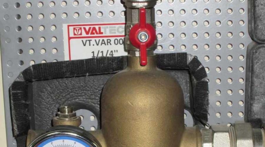
Now look at the photo from a real example of such arrows:


The diameter of the hydraulic arrows reaches madness...
The coolant speed in such hydraulic arrows can reach 0.5-1 m/s.
And the advantage: It is a simplified form, easier to install and inexpensive.
Not a standard solution for the manufacture of hydraulic arrows
In most cases, hydraulic arrows are made of steel or iron pipes large diameter. And if you want not to install iron elements in the heating system, which rust and spread rust throughout the system? And it is difficult to find large diameter ones made of plastic or stainless steel.
Then a diagram in the form of grids of small-diameter pipes will come to the rescue:

This design can be assembled from pipes of the original diameter of the nozzles, connecting with any tees. For example, from a diameter of 32 mm. You can also use polypropylene, only for low temperatures heating no higher than 70 degrees. You can use copper pipe.
It would be cheaper and easier to replace this structure with ( heating device). But in this case you will have to carry it. Or insulate the radiator.
See image:

Very often the following manifold is used with a hydraulic arrow:

For such a circuit, the temperature entering the supply circuits (Q1, Q2, Q3, Q4) is the same for all.
The collector diameter is taken large to eliminate hydraulic resistance when turning for each circuit. If you do not increase the diameter of the collector, then the hydraulic resistance at turns can reach such values that it can cause uneven coolant consumption between the circuits.
The calculation of diameters is also calculated trivially using the following formula:
Do you want to create a temperature gradient in the manifold?
It's possible! See image:

In this scheme, balancing valves are installed between the supply and return manifolds, which make it possible to reduce the temperature pressure on the last (right) circuits. Patency balancing valves should be as large as possible and equal to pipeline (d). It is also necessary to put on pipeline (d) for a stronger gradient distribution. Or reduce its diameter, according to calculations based on hydraulic resistance.
Also don't forget that there are mixing units for heated floors, on which you can also regulate the temperature pressure.
Is it worth buying a ready-made hydraulic gun?
Generally speaking, hydraulic guns are an expensive pleasure.
Numerous options were described above on how to make a hydraulic arrow yourself or use a non-standard solution method. If you don’t want to save money and make it beautiful, then you can buy it. If there are problems, you can use the methods described above.
Why is the coolant temperature after the arrow (hydraulic separator) less than at the inlet?
It's connected with various expenses between contours. The incoming temperature into the hydraulic arrow is quickly diluted with the cooled coolant, because the flow rate of the cooled coolant is greater than the flow rate of the heated coolant.
The main advantages of using hydraulic booms
If we compare it with a conventional system, where everything is connected by one circuit, then when some branches are turned off, a small flow rate occurs in the boiler, which increases the sharp increase in temperature in the boiler and the subsequent arrival of a very cool coolant.
The hydraulic arrow helps to maintain constant flow boiler, which reduces the temperature difference between the supply and return pipes.
To significantly reduce the temperature pressure, it is necessary to change the direction of movement of the coolant in the hydraulic arrow, which will reduce the temperature pressure!
Rather, it is possible to buy several weak pumps and increase the functionality of the system. Distributing them into separate circuits.
3. Durability of boiler equipment?
Most likely, it was meant that the flow through the boiler is always stable and sudden jumps in temperature pressure are excluded.
If we compare it with a conventional system, where everything is connected by one circuit, then when some branches are turned off, a small flow rate occurs in the boiler, which increases the sharp increase in temperature in the boiler, and then the arrival of a very cool coolant in the boiler.
4. Hydraulic stability of the system, no imbalance.
This means that when there are many circuits or branches (flow distribution) in the heating system, there is a shortage of coolant flows. That is, we cannot increase the flow rate in the boiler more than what is established by its bore diameter. And one weak pump will not increase the flow rate to the required value. And a hydraulic arrow comes to the rescue, which makes it possible to get additional expense coolant.
Many questions arise about whether a hydraulic gun is needed and what real benefits it will bring. Let's consider typical heating systems of private houses, and those cases when significant money on complications with a hydraulic arrow is wasted in vain, and with the introduction of harm.
The complexity of the circuit increases the likelihood of breakdowns and errors, and the cost of repairs. May result in inefficient modes, lack of power supply, for example, when the boiler is hot and the batteries are cold...
The basic rule for installing a heating system for a home is to simplify and reduce the cost of the design as much as possible (and not vice versa - to clutter up and confuse...). The inclusion of a hydraulic insole adds complexity, significantly increases the price, and allows installers to make a lot of money.
Thick pipe with bends
Typically, a hydraulic arrow looks like a thick barrel with many outlets for connecting all the main circuits of the house. Returns are connected to the connections in the lower part (located vertically), in the upper part - supplies, on the one hand - boilers and heaters, on the other - consumer circuits - floors, radiators, DHW.
The pressure inside the hydraulic needle is almost the same at any point. Therefore, it is the same at all connections. Therefore, any pump that turns on/off will not have a significant impact on the adjacent parallel circuit.
Typical diagram without hydraulic arrow
In the diagram, they are connected to the boiler distribution manifolds, from which many circuits with their own pumps branch off.

We see that when any of these pumps is turned on, the pressure in the adjacent circuits will change significantly (liquid intake from the boiler supply will increase, the supply pressure will decrease and the return pressure will increase). This will affect the fluid flow from neighboring circuits.
The pump can reduce/increase the amount of fluid passing in a neighboring circuit, “where it was not asked for” - for example, when the “dog kennel” is turned on, the heating of the “wild orchid in the greenhouse” will stop. But Bobik in the kennel is not to blame for the death of the flower, he was not the one who forgot to insert the hydraulic arrow into the complex diagram...
How does heating work with a hydraulic arrow?
Now let's look at what happens when all the supplies and returns are connected to a piece of large diameter pipe.

Turning on the pumps no longer significantly changes the pressure in the system. Now, first of all, the amount of liquid passing through the hydraulic arrow will change, but the system itself will remain stable. Therefore, the inclusion of “garage” will not surprise users in the area of the “sauna” circuit.
More often, the circuit is connected not through a manifold, but directly to the connections on the hydraulic arrow itself, which reduces the cost...
 You can assemble a hydraulic arrow from metal with your own hands
 Fluid movement through a hydraulic separator
As a rule, liquid moves from the supply to the return. This means that the flow rate of the boiler circuit is always greater than the liquid intake by consumers. This must be provided in the system. Partial operation of the boiler “on its own” is allowed and is useful in terms of increasing the return temperature.

The movement of fluid from the return to the supply indicates abnormal operation - emergency mode. The result is too cold a return, a hot boiler and cool consumers. Allowed for a short time, while troubleshooting.

Additional functions of the hydraulic arrow
The hydraulic arrow also combines the functions of a separator. When the speed of movement of a liquid changes, the air dissolved in it is released and rises upward in the form of bubbles, forming air lock. Therefore, the device is usually equipped with an automatic air vent.
Also, particles of sludge settle below, accumulating silty deposits, so a large diameter tap is installed at the bottom of the device. Branded water guns, for better separation of all unnecessary things from the coolant, are also equipped with separator swirlers, but they are expensive...
 Branded hydraulic separator with supply and return manifolds
 Diagram of primary and secondary rings instead of a hydraulic arrow
Experts often prefer a scheme of primary and secondary rings instead of a hydraulic gun, which, in their opinion, is somewhat simpler, cheaper, and works more stable.

The boiler drives the coolant along a short ring - from the supply to the return, to which all circuits with pumps are connected by a pair of connections, and the distance between the supply and return tees of each circuit is no more than 30 cm. The temperature along the connection ring decreases, so the first circuits are the hottest.... The hot water supply is connected first, the warm floor is the last... The scheme works great in private homes.
 You can find cheap products made of polypropylene
 When you definitely don’t need a hydraulic meter and when you will need it
Businessmen and “craftsmen” are trying to impose a hydraulic arrow on residents, installation is not required pumps, and “make money” both on the equipment itself and on its installation. The cost of the system can be increased using the question “how can we do without a hydraulic gun”, and by 1000 USD. and for 2000 USD….
A hydraulic arrow will not help the system if it is simple and all branches can be powered by the boiler pump, or with a constantly running auxiliary pump. You can do without a hydraulic separator if you only have:
- radiator circuit,
- indirect heating boiler,
- warm floor,
whose work is easily coordinated.
But, when you include another boiler with its own pump in such a scheme (not a backup one, but an auxiliary one that is constantly running), it will be necessary to equalize the pressure. Or when another “flickering” consumer pump is turned on, for example, a “greenhouse”.
You will also need a hydraulic arrow when there are many secondary circuits with pumps and they all operate in their own modes.