Flexible connection for impulse tube. Impulse pipe. Impulse tubing connections
The impulse tube is used to remove pressure and connect impulse lines to flow and pressure regulators. Besides this, this is another one of inexpensive options solutions for high temperatures of the measured medium. Each meter of impulse tube lowers the temperature of the medium by approximately 80 degrees. Typically steel or copper impulse tubes are used. One end of the impulse tubing, connected to the pressure source, has the most convenient thread for G1/2 mounting, and the other end, connected to the sensor or regulator, has a thread that matches the threads of the equipment.
For example: for the convenience of installing pressure sensors, the AKVA-KIP company offers an impulse tube (copper) with threaded internal and external connections of any length for supplying pressure. The copper tube can withstand pressure up to 87 bar and at the same time bends easily, which allows you to lay it in place from the pressure tapping point to the device without much effort and additional tools.
Characteristics:
Copper tube: 10x1
Pressure (max): 87 bar (30 bar for threaded fittings)
Temperature: -25+210 C
Thread of connection to the process and to the device: G1/2, G1/4, G3/8 (if requested, indicate internal or external)
The price is indicated for an impulse tube 1 meter long and with a G1/2 thread.
Length: 1 meter (we accept orders for the production of tubes of any length; to calculate the cost and production time, please contact the company’s managers)
To obtain gas flows at super- and hypersonic speeds, in which the outflow of the working gas occurs from the closed volume of the pre-chamber. A diaphragm is installed in the subsonic part of the nozzle (see figure), separating the prechamber from the gas-dynamic path of the pipe. The prechamber is filling compressed gas , a vacuum is created in the remaining elements of the pipe (101 Pa). As a result of a powerful electrical discharge of a capacitor bank or inductive storage in the prechamber, the working gas is heated, its temperature and pressure increase to T 0 ≈(35)*10 3 K and 0 ≈(23)*10 8 Pa. After this, the diaphragm breaks, and the gas rushes through the nozzle into the working part and then into the vacuum tank. The outflow of gas is accompanied by a drop in pressure and temperature in the prechamber both due to gas expansion and due to heat losses into the pipe walls, but in the working part during the operating mode it practically does not change over time and is determined mainly by the ratio of the areas of the outlet and critical sections nozzles Duration of the operating mode (pulse hence the name) in I.t. is 50 x 100 ms, which is sufficient for carrying out various types of aerodynamic tests.
The short time of exposure of dense high-temperature gas to pipe elements and the model removes strict restrictions on the materials used for pipe and model structures and measuring equipment, eliminates the need for complex systems cooling and thereby significantly simplifies and reduces the cost of conducting experiments.
IN I.t. it is possible to obtain very large Reynolds numbers, therefore I.t. allow testing of models aircraft in conditions close to natural. However, the unsteadiness of the flow and contamination of the gas flow with destruction products of the electrodes and prechamber walls limit the possibilities I.t.
A. L. Iskra.
Encyclopedia "Aviation". - M.: Great Russian Encyclopedia.
Svishchev G. G.
1998. See what an “impulse pipe” is in other dictionaries: Impulse pipe
- a wind tunnel for producing gas flows at super and hypersonic speeds, in which the outflow of the working gas occurs from the closed volume of the pre-chamber. A diaphragm is installed in the subsonic part of the nozzle, separating the prechamber from... ... Encyclopedia of technology
Impulse pipe diagram. impulse tube wind tunnel for producing gas flows at super and hypersonic speeds, in which the outflow of working gas occurs from a closed volume prechamber. In the subsonic part of the nozzle... ... Encyclopedia "Aviation" magnetic pulse welding- Welding using pressure, in which the connection is made as a result of the collision of the parts being welded, caused by the influence of a pulse magnetic field
. [GOST 2601 84] [Terminological dictionary for construction in 12 languages (VNIIIS... ...- 46. Magnetic pulse welding Welding using pressure, in which the connection is made as a result of the collision of the parts being welded, caused by the influence of a pulsed magnetic field Source: GOST 2601 84: Welding of metals. Terms and...
GOST R ISO 857-1-2009: Welding and related processes. Dictionary. Part 1. Metal welding processes. Terms and Definitions- Terminology GOST R ISO 857 1 2009: Welding and related processes. Dictionary. Part 1. Metal welding processes. Terms and definitions original document: 6.4 automatic welding: Welding, in which all operations are mechanized (see table 1).… … Dictionary-reference book of terms of normative and technical documentation
GOST 23769-79: Electronic devices and microwave protective devices. Terms, definitions and letters- Terminology GOST 23769 79: Electronic devices and microwave protective devices. Terms, definitions and letter designations original document: 39. π type of oscillations NDP. Antiphase type of oscillations A type of oscillations in which high-frequency voltages ... Dictionary-reference book of terms of normative and technical documentation
Yokogawa has developed functions that diagnose blockages and control the impulse tube heating system specifically for the EJX series pressure transmitters. This article describes advanced diagnostic functions with digital communications using the FOUNDATION Fieldbus and HART protocols.
Yokogawa Electric CIS LLC, Moscow
Introduction
It is assumed that control and measuring instruments should be equipped with diagnostic functions that make it possible to prevent abnormal process conditions and, in addition, the possibility of their expansion should be provided. Diagnostic information based on various parameters of the physical process measured by instruments, and its further use, allows the user to reduce the amount of routine maintenance and thus reduce the cost of its implementation. Instrumentation with advanced diagnostic capabilities enhances process control capabilities and reduces production costs. Maintenance (1).
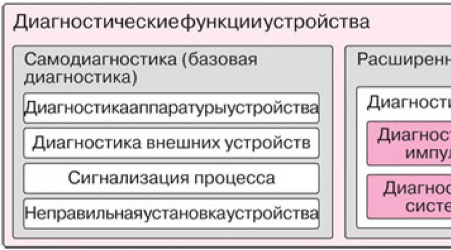
Yokogawa EJX Series pressure transmitters diagnose blockages in the impulse tubing used to transmit process pressure to the sensor and monitor the condition of the impulse tubing heating system at the connection points. technological equipment. The first function - detection of blockages in impulse tubes - is based on the use of pressure fluctuations in the working medium that occur in the tubes. Another function is the control of the impulse tube heating system, designed to prevent the fluid in the tubes from cooling, based on the use of a temperature gradient corresponding to the thermal resistance inside the sensor. In contrast to the self-diagnostic functions, these functions are called the advanced diagnostic functions of the EJX series pressure sensors. In Fig. 1 shows the configuration of diagnostic functions.

Rice. 1. Configuration of diagnostic functions in EJX series instruments
In Yokogawa's dedicated technical reports (2), (3), specialists will be able to study more detailed description the above functions and principles of their operation.
Overview of advanced diagnostic functions
Enhanced diagnostic capabilities of the EJX Series pressure transmitters for differential, absolute and overpressure, as well as temperature, make it possible to detect abnormal process conditions by monitoring the state of the process environment using special algorithms, which will be discussed below.
Detection of blockages in impulse tubes
Pressure sensors measure the pressure of the process fluid supplied to them through impulse tubes. The impulse tubing connecting process outputs to the transmitter must accurately transmit process pressure. If, for example, gas accumulates in a liquid-filled tube during inflation or the channel becomes clogged, pressure fluctuations occur, it begins to be transmitted inaccurately, and the measurement error increases. That's why a necessary condition accurate measurements is the possibility of using sensors with advanced functions for determining clogging in tubes to reduce the amplitude of pressure fluctuations when blocking impulse tubes, namely by comparing the degree of attenuation of the amplitude of pressure fluctuations with the initial values obtained when measuring pressure under normal conditions.
In Fig. 2 shown typical installation impulse tubes for the differential pressure sensor and a schematic diagram giving an idea of the change in the amplitude of pressure fluctuations under normal conditions and during blocking.

Rice. 2. Installation of impulse tubes for a differential pressure sensor and attenuation of the amplitude of pressure fluctuations
Monitoring the condition of the impulse tube heating system
Required temperature steam and heater, which maintains the temperature of the impulse tubes, are controlled by measuring the flange temperature, determined based on the temperatures of the capsule and sensor amplifier. In Fig. 3 presented standard design impulse tube heating system, consisting of a copper tube for steam, an impulse tube and insulating material, and in Fig. Figure 4 shows a graph from which the flange temperature can be estimated based on the temperatures of the capsule and amplifier.

Rice. 3. Impulse tube heating system

Rice. 4. Flange temperature estimation based on capsule and amplifier temperatures
Application of advanced diagnostic functions in EJX series pressure sensors
EJX series pressure sensors are capable of diagnosing blockage of impulse tubes on the side high pressure, on the side low pressure or on both sides. This is made possible by using a multi-parameter silicon resonant sensing element that can simultaneously measure differential pressure, high-side static pressure and low-side static pressure (4). Therefore, EJX series pressure sensors are designed not only for differential pressure measurement and level detection, but also for blockage detection in the impulse pipes on the pressure measurement side using the same measurement principle. With their help, the temperature of the flange of any design shape can be controlled, since it is based on the temperatures of the capsule and amplifier.
Advanced pressure transmitter diagnostics are available on all models that support FOUNDATION Fieldbus and HART digital communications protocols. In table 1 shows a list of EJX series pressure sensor models and clogging detection options for each of the models presented.
Table 1. EJX series models and applicable blockage detection objects

In table Figure 2 shows the characteristics of sensors with advanced diagnostic functions for the two digital communications protocols FOUNDATION Fieldbus and HART. The difference is observed in the purpose of diagnostic alarm outputs, the number of alarm settings, etc.
Table 2. Characteristics of advanced diagnostic functions

Advanced Diagnostics Data Processing
In Fig. Table 5 shows the sequence of actions performed when processing advanced diagnostic data, and table. Figure 3 shows the output parameters related to the corresponding diagnostics.

Rice. 5. Advanced diagnostic algorithm
Table 3. Diagnostic related output

Yokogawa EJX series pressure sensors diagnose clogging in impulse tubes by detecting variations in differential pressure, high-side static pressure, and low-side static pressure at intervals of every 100 ms or 135 ms, and then statistically processing the results based on the data. . For each diagnostic period important characteristics are the following: the ratio of fluctuations of the nominal and diagnosed values, as well as the degree of blocking, determined on the basis of the correlation of pressure fluctuations. Note that the diagnostic period can be changed through the appropriate settings.
When monitoring the status of the impulse tube heating system at 1 second intervals, the flange temperature is determined based on the capsule and amplifier temperatures and an appropriate estimate is made by comparing the obtained value with the upper and lower threshold values.
While the system evaluates all parameters, the required diagnostic parameters are selected and, in accordance with the alarm output setting, the resulting diagnostic result is displayed.
When using the FOUNDATION Fieldbus communication protocol, diagnostic alarms are displayed not only in the status output value, but also in the function block analog input (AI) output. When using the HART communication protocol, the available outputs are not only cut-off and emergency transition analog signal 4–20 mA, but also contact output.
Below is a description of the basic procedures performed when diagnosing blockages in the impulse tubes and monitoring the condition of the impulse tube heating system.
Algorithm for diagnosing blocking of impulse tubes
The main step in the process of diagnosing clogged impulse tubes is monitoring pressure fluctuations. Blockage is determined by comparing the pressure fluctuation values of the current process with the nominal value corresponding to the operating pressure. Basically, when the differential pressure and static pressure are high, the fluctuation values are also high, so the blockage detection process is stable. However, if the level or pressure of a highly viscous process fluid with a viscosity coefficient of more than 10 cSt is being measured, or the medium being measured is a gas, then it must be taken into account that the values of pressure fluctuations should not be high so that measurement errors do not occur.
Blockage diagnostics are performed in the following sequence: setting nominal values, simulating the situation with confirmation of blockage detection, and detecting blockage in real conditions. Simulation of a tube blockage situation is performed using a three-valve manifold or shut-off valve, mounted on impulse tubes.
In this case, the nominal values of pressure fluctuations are quite large. To perform diagnostics, it is necessary to select the minimum limit for the pressure fluctuation value. Diagnostics will only be possible if the pressure fluctuation values exceed the specified minimum limit.
Diagnostic function parameters are configured using the Integrated Device Management Software Package PRM (Plant Resource Manager) and Versatile Device Management Wizard FieldMate software packages developed by Yokogawa (5), (6).
Algorithm for monitoring the condition of the impulse tube heating system
Since the flange temperature is determined based on the temperatures of the capsule and the sensor amplifier, it is necessary to determine the appropriate coefficient for its calculation.
To do this, before performing the diagnostic procedure, it is necessary to heat the flange and measure its temperature. After this, the resulting coefficient is set in the device, as well as alarm thresholds for high and low temperatures.
Alarm Alert Selection Algorithm
In Fig. Figure 6 shows a diagram for selecting alarms for pressure sensors with a communication type using the HART protocol. The resulting blockage diagnosis and flange temperature error are stored in the Diag Error parameter, and the output and display of the results are determined by the Diag Option.

Rice. 6. Alarm (for digital communication via HART protocol)
When using the FOUNDATION Fieldbus communication protocol, the diagnostic results are contained in the DIAG_ERR parameter and the output data is determined by the DIAG_OPTION parameter.
Graphical user interface (GUI) for advanced diagnostics
Device Type Manager (DTM) software FieldMate is equipped with special user interface shown in Fig. 7, with the help of which various sensor parameters are set and monitored. The GUI interface makes it easy to obtain the nominal value for blockage diagnostics and flange temperature coefficient, and also facilitates the selection of alarm protection.

Rice. 7. System interface example
Pressure swing values and blockage levels can be observed and controlled in the Device Viewer tabs of the FieldMate software. In Fig. 8 shows examples of these tabs. Changes in diagnostic data that occur when the valve is turned can be visualized during the blockage modulation performed when setting up the blockage diagnostics.

Rice. 8. Examples of diagnostic information screens and changing information in Device Viewer
Conclusion
Archiving diagnostic information obtained as a result of using the devices described in the article and its further analysis allow for accurate diagnostics and control of technological processes. This is accomplished through the use of EJX Series pressure sensors and Yokogawa's Integrated Device Management Software Package PRM (Plant Resource Manager).
Due to the recent increase in the volume of various operations technological process Manufacturing requires instrumentation with advanced diagnostic functions to improve functionality and measurement accuracy. Yokogawa products not only meet all of the above requirements, but also enable the implementation of solutions of the highest level.
Impulse tubes are auxiliary equipment, used with control and measuring instruments of the pipeline working environment - converters, pressure gauges, pressure/vacuum sensors. Installation of the device is carried out on process pipeline. Can be connected to some devices automated system. The temperature of the working environment is reduced to the level necessary for interaction with measuring equipment. Helps reduce pressure surges and eliminate vibration.
There are two design options for impulse tubes for connection to the pipeline - threaded and welded. Thanks to this device increases the resistance of control and measuring devices to the effects of adverse climatic conditions, aggressive working environments. Widely used in areas of heating networks, as part of the equipment of heating points.
Impulse tubes remove pressure and provide connection between devices that regulate pressure and flow of the working medium with the impulse line. Are considered in an accessible way carrying out measurements of the environment with high temperature(unless the measuring and control equipment is designed to work with high-temperature liquids).
The effectiveness of the device is determined by its length - 1 meter is enough to reduce the temperature by 80 degrees. Common manufacturing materials are copper and steel. Table of the dependence of the sizes of impulse tubes on the material:
One end of the tube is connected to a pipeline or apparatus with a working medium, and the other to a measuring device. The thread of the connection side to the pressure source is G1/2, the connection side to the sensor is according to the thread of the sensor.
The selection of impulse tubing is entirely determined by the operating conditions and planned connections. Available with internal and external threads, in various lengths. Typical copper modifications are capable of working with systems having a pressure within 87 bar (the permissible pressure in areas with fittings is 30 bar), and are convenient for installation. The softness of the material allows you to give the device the required form and lay the tube to a permanently placed monitoring device (without using additional tools).
Standard length tubes - meter, it is possible to manufacture modifications of any length, with any connection options. Purchasing a device is possible even if the required length is unknown. A pipe of obviously longer length is purchased (with prepared connections at the ends), the excess is cut off during installation, and the cuts are fixed with clamp fittings.
Auxiliary fittings for pressure measuring instruments include a device such as a Perkins tube, otherwise called an impulse tube for a pressure gauge or a loop tube. It is intended for reliable protection device from possible fluctuations in the measuring medium and from excessive heating. Using a tube, the temperature at the point of contact of the device with the system is lowered. In addition, the tube serves as an adapter from the pressure gauge to the pipeline.
Condensation accumulates in the cavity of the impulse tube, preventing the high-temperature medium being measured from entering the middle of the pressure gauge. When putting the line into operation, you need to make sure that there is coolant in the steel tube.
The Perkins loop tube is used to measure liquids and gases that are not strong reagents. In this capacity and as an intermediary between devices and pipelines, the impulse tube is the most economical profitable option connections. The use of such a tube can extend the life of the measuring device by many years. In the best way connection of this type of fittings to a pipeline system is considered to be the use threaded connection. In some cases, the connection is made by welding. Impulse tubes are made from various brands high quality steel. If there is a need to install pressure sensors, then for their installation use copper tubes Perkins.
Impulse tube having corner structure, used for installation on it measuring device and connections to pulse systems. Sometimes such tubes are made of brass. Straight loop tubes are used in the same cases. General purpose This additional equipment is to dampen vibrations and pulsations in the measured medium and prevent the pressure gauge from heating up.
On the pages of the Soyuzpribor LLC online store you will find pressure tapping devices, connecting hoses, various adapters for pressure gauges, frames, dampers, bosses and other types of additional equipment.
Connecting sleeve
To create normal temperature conditions connection of the diaphragm seal to measuring instrument must be carried out either through a connecting hose or through a supply pipe, which is installed by the consumer between the pressure tapping point and the separator.
GSP pneumatic measuring pressure transducers are always connected to the separator via a sleeve.
When installing the separator with a connecting sleeve, displacement in height is allowed, while taking into account the installation error of the measuring device with upper limit measurements up to 1 MPa, determined by the hydraulic pressure of the separating liquid column in the connecting sleeve.
The standard connecting hose, model 55004, has a length of 2.5 meters when deployed.
Damping device
The damping device is resistant to ambient temperatures from minus 55 to plus 70 °C, at relative humidity from 30 to 80% over the entire temperature range, and are also resistant to relative humidity of 95% at a temperature of 35 ° C (for version U) and relative humidity up to 100% at a temperature of 35 ° C (for version T).
Valve block
Valve blocks BC are intended for connection to lines with the measured medium of instruments for measuring excess and vacuum pressure. The blocks allow you to cut off instruments from lines without releasing the pressure of the measured medium, check the zero value of instrument readings, or purge impulse lines. For lines measuring oxygen pressure, parts in contact with the medium being measured are degreased and marked “K”.
Adapters and couplings (boss)
coupling and adapter for pressure gauges or thermometers are connecting (connecting) fittings used in systems (pipelines) for transportation gaseous media and liquids of low viscosity and non-crystallizing nature. At their core, these products are additional (auxiliary) equipment.