Arbitrary Waveform Generator. A simple digital arbitrary waveform generator. User interface, generator control and mode display
Read also
Why signal generators are needed freeform
When testing various systems their developers should investigate the behavior of the system when both standard signals and signals with various deviations from the norm are applied to its input. AT real conditions work on the system may be affected by interference that distorts the shape of the signal, and the developer needs to know how the device will behave under certain distortions. To do this, he needs to either simulate interference during the passage of a standard signal, or apply to the input a distorted signal obtained using an arbitrary waveform generator (ASPF). The first path is much longer and more expensive, so the second path is most often used.
Arbitrary waveform generators are also used in cases where, for debugging and testing devices, it is necessary to apply signals to their input. non-standard shape, which are extremely difficult to obtain without the use of such generators.
The concept of building GSPF
The construction of the GSPF is based on the synthesis analog signal according to its image, recorded in the RAM of the generator. The typical structure of the GSPF is shown in fig. 1.
Rice. 1. Typical Arbitrary Waveform Generator StructureThe phase angle generator (GFU) generates a periodic linearly increasing sequence of RAM cell addresses (signal phase). The steepness of the sequence depends on the frequency set by the control unit (CU).
In accordance with the change in the addresses at the input of the RAM, the data at its output also change. The sequence of output data forms a digital image of the generated signal. It is converted to analog form using a digital-to-analog converter, then the signal is attenuated in accordance with the specified amplitude, and the desired constant offset is introduced into it. After amplification, the output signal is desired shape, frequency, amplitude, with the required constant offset.
Generator Specifications
-
Frequency of generated signal 0.0001…22000 Hz
-
Output signal amplitude 0…10 V
-
DC output bias -5…+5V
-
Output current up to 100 mA
-
Number of readings per period 8192
-
Temperature relative frequency instability less than 10 -5 1/
°C -
Long-term relative frequency instability less than 10 -5 1/1000 h
-
Frequency setting accuracy 7* 10 -6 Hz
-
Supply voltage 10…12 V
-
No load power consumption 0.9 W
-
Overall dimensions of the generator board 125x100x15 mm
Structure of the GSPF complex
The hardware-software complex for generating arbitrary waveforms consists of the generator itself, connected to the computer via the RS-232C serial port, and the generator control program running under Windows 95/98, Windows NT 4.0.
Generator hardware structure
The hardware part is made in accordance with the structure shown in fig. 1. The only difference is that the control unit of the developed generator is connected to the computer through the interface unit. From the computer, using the control program, the shape and other parameters of the signal are set.
Control blockThe generator is based on the AT89C52 microcontroller. It receives commands from the computer to change the parameters of the signal and issues the corresponding commands to other blocks of the generator. In addition, the generator has an SPI-like interface for connecting a non-computer control device. The presence of such an interface will allow the generator to be used as part of a mobile compact complex for removing frequency characteristics which is currently under development.The control unit receives and sets the frequency, offset and amplitude of the signal. Data on the shape of the output voltage also passes through the control unit. Standard shapes (saw, square, white noise and sine) are calculated directly by the microcontroller.
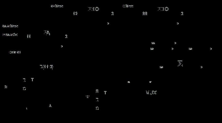
Signal amplifierbuilt around the low-noise operational amplifier MAX427 and allows you to get the output current up to 100 mA. DC bias DAC AD7943- multiplying 12-bit DAC with serial data input, which allows you to get a signal offset in the range from -5 V to +5 V with a resolution of 2.44 mV. Amplitude DAC AD7943- multiplying 12-bit DAC with serial data input. Allows you to set the amplitude of the output signal in the range from 0 to 10 V with a resolution of 2.44 mV. DAC MX565A- high-speed 12-bit DAC with parallel data input. The settling time with an accuracy of half the least significant digit is not more than 250 ns. RAM UM6264 contains a digital image of the form. The shape is stored as 8192 12-bit samples. This allows you to get an output signal of sufficiently high quality. Phase angle generatorbuilt on the basis of the ALTERA EPF8282 FPGA. The structure recorded in the FPGA is shown in fig. 2.
Rice. 2. Structural scheme FPGA configurations
The circuit can operate in three modes:
In the normal generation mode (at the inputmode unit) the phase increment register (PFR) is loaded from the CU with the value corresponding to the frequency.
During normal generation, the contents of the RPF are summed with the least significant bits of the phase register (RF), and the sum is written to the RF upon arrivalSI. Thirteen senior digits of the Russian Federation are fed to the address inputs of the RAM block. Thus, the RF overflow frequency corresponds to the frequency of the generated signal.
In standby mode (inputmode zero) HFC is waiting for the arrival of the strobe signal at the inputstrob. Upon arrival of this signal, a signal is generated from the initial phase recorded in the initial phase register (RNF) to the end of the period. After the end of the period, the HFC again enters the gate waiting state.When loading data into RAM, they are first sequentially written to the data register (RD), and then, when a signal is given
InRAMOE, exposed to the data inputs of the RAM block. This is done to save the number of microcontroller pins used and to simplify the PCB topology.As can be seen from the FPGA structure, the implementation of such an operational machine on microcircuits with a low degree of integration would require a large number elements of different types (more than 30 cases), which would lead to an increase in dimensions and a decrease in the reliability of the system. Therefore, it is convenient to use FPGA.
Prototype generator
The prototype was assembled on a double-sided printed circuit board size 175
x 110 mm. Consumption prototype no load is 0.9 W.The appearance of the prototype generator is shown in fig. 3.

Rice. 3. View of the generator board prototype
Generator control program
A two-channel virtual digital arbitrary waveform generator is a 12-bit digital device in the standard design of devices of the AKTACOM USB-laboratory series, and generates an arbitrary waveform signal or a signal of one of standard forms(sinusoidal, rectangular, triangular and some others) on two channels simultaneously. Setting the form and parameters of signals is performed by the user using a computer independently for each of the channels. The device has an external synchronization input common for both channels to start generation on an external event. The signal generator also provides an output to synchronize the triggering of other instruments.
Signal Generator Specifications
| General characteristics | |
|---|---|
| Number of output channels | 2 |
| Output Waveform | arbitrary or standard |
| Shape selection for both channels | independent |
| DAC | 12 bit |
| Maximum number of points per channel | 128 K |
| Switchable low pass filter | 15 MHz |
| Maximum sample rate | 80 MHz |
| Bandwidth at 1% level | 0...10 MHz |
| Maximum output level peak-to-peak: without additional amplifier with additional amplifier (only for AHP-3122) |
±2.5 V into 50 ohms ±20 V into 50 ohm load |
| Output voltage step | no more than 2.5 mV; 10 mV with amplifier |
| Limits of signal shift change along the vertical | ±2.5 V |
| Rectangular rise time | no more than 20 ns |
| Sampling frequency | selectable from 2.44 kHz to 80 MHz |
| Error | no more than 10 -6 of the output frequency |
| Synchronization | |
| Choice of timing modes | |
| restart | single or continuous |
| a source | external or manual (internal) |
| polarity | rising or falling edge |
| External sync input | |
| the form | square wave |
| amplitude | TTL level |
| duration | at least 25 ns |
| Synchronization output | |
| the form | square wave |
| amplitude | TTL level at 1 kΩ load |
| duration | at least 25 ns |
| Power and design parameters | |
| Nutrition | 220 V, 50 Hz, max 20 W |
| dimensions | 260x210x70mm |
| Weight | no more than 2.0 kg |
| Relative Humidity | no more than 90% at a temperature of 25°C |
| Atmosphere pressure | 495 to 795 mmHg Art. |
AKTAKOM ARBITRARY GENERATOR SOFTWARE
PURPOSE:
The AKTAKOM Arbitrary Generator application is designed for full-featured control of supported instruments, creation, editing and loading of data to generate signals for two channels.
OPPORTUNITIES:
The application provides detection and compilation of a list of signal generator modules available for operation, connected to the computer locally (by USB interface) or via the Ethernet/Internet network; initialization and testing of the selected device instance.
The application manages all the parameters available for configuring this type of hardware (see description of supported devices) and writes waveform data to the signal generator's memory. The waveform data can be specified graphically by the user, in the form mathematical formula(there is a built-in formula calculator) or a binary sequence: selected from a list of standard signals (sine, rectangle, triangle, saw, flash, impulse) or be loaded from a previously saved file independently for each channel.
The application also allows you to set the waveform for two channels simultaneously in the form of a parametric curve, i.e. in the form of a two-dimensional Lissajous figure (Laser Show function).

The application contains a built-in analysis module for signals prepared for generation. The functions of the analysis module include:
- virtual oscilloscope (shows the shape of the generated signals, taking into account the limitations of the equipment);
- automatic measurement of pulse parameters;
- spectral analysis of signals;
- functions of a voltmeter and a phase shift meter.
The application allows the user to manually adjust the colors of the graph elements and the thickness of the lines of the waveforms, or load these settings from previously saved files. color schemes. The size and position of all application windows can also be configured by the user. All program settings can be written to a configuration file and then loaded.
Minimum computer requirements
- USB 1.1 port;
- Installed operating system Windows XP, Windows 7, Windows 8;
- VGA video system (640x480 resolution, 256 colors), 800x600 resolution or more recommended, 24-bit color;
- A sound card and an audio system are required to use the program's audio messages;
- To use all the features of the program, we recommend using at least a Pentium II 400 processor and at least 32 MB of RAM.
Standard equipment
- device
- USB cable type A-B- 1 PC.
- power cable
- short instruction
- manual**
** Complete Guide The instruction manual in the standard delivery does not have a physical medium and can be downloaded from the site after purchasing and registering the device with its serial number.
- Software
- AAG Aktakom Arbitrary Generator Arbitrary Waveform Generator Software
- AUNLibUSB 1.2.6.0 Driver for USB Lab Virtual Instruments
For loading software click the "Download" button or go to the section "" ->
Additional equipment
- BNC cable and
- Software AHP-3121_SDK Complete Software Development Kit
The software in the standard delivery does not have a physical medium and can be downloaded on the website in the “ ” section after purchasing and registering the device, indicating its serial number.
To download the software, click the "Download" button or go to the "" -> "" section, then log in by entering your login and password. If you have not previously registered on the site, follow the link "Register" and provide all the necessary data.
If the software is lost, it will be downloaded at an additional cost. The software may be delivered on a physical medium (CD). Recording the software on a medium (CD) and its delivery are carried out for an additional fee.