Peltier elements. Operation and application. The opposite effect. What is a Peltier element, its structure, operating principle and practical application Joule-Lenz heat and Peltier heat
Read also
PELTIER EFFECT
PELTIER EFFECT
Release or heat during the passage of electricity. current I through the contact of two different. conductors. The release of heat is replaced by absorption when the direction of the current changes. French opened physicist J. Peltier in 1834. Amount of heat Qp=PI, where P is the Peltier coefficient, equal to: P=TDa. Here T is abs. temp-pa, Da-difference thermoelectric. coefficient conductors.
P. e. explained by the fact that cf. current carriers depends on their energy. spectrum, concentration and mechanisms of their scattering and therefore varies in different conductors. When moving from one conductor to another, electrons either transfer excess energy to atoms or replenish the lack of energy at their expense. In the first case, Peltier is released near the contact, and in the second, Peltier is absorbed. During the transition of electrons from a semiconductor to a metal, the energy of the conductivity electrons of the PP is significantly higher than the Fermi level of the metal, and the electrons give up their excess energy. When the current is in the opposite direction, only those electrons whose energy is above the bottom of the conduction zone of the PP can pass from the metal to the PP. The thermal equilibrium in the metal is disturbed and restored due to thermal vibrations of the crystals. grates. In this case, Peltier heat is absorbed. At the contact of two PP or two metals, Peltier heat is also released (or absorbed) due to the fact that cf. The energy of charge carriers on both sides of the contact is different.
P. e. used for cooling in refrigeration units and in certain electronic devices.
Physical encyclopedic dictionary. - M.: Soviet Encyclopedia. . 1983 .
PELTIER EFFECT
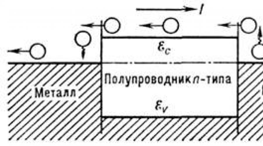
The release or absorption of heat at the contact of two dissimilar conductors, depending on the direction of the electricity. current flowing through the contact. Discovered by J. Peltier in 1834. Heat release power Q= P 12 j, Where j- current density, P 12 = P 1 - P 2 (P 1, P 2 - absolute Peltier coefficient of contacting materials, which are characteristics of these materials). The cause of P. e. is that cf. energy of charge carriers (for certainty of electrons) participating in electrical conductivity, in decomp. conductors is different, because it depends on their energy. spectrum, concentration and scattering mechanism (see. Charge carrier scattering). When moving from one conductor to another, electrons either transfer excess energy to the lattice or replenish the lack of energy at its expense (depending on the direction of the current). In the first case, near the contact it is released, and in the second, the so-called is absorbed. Peltier heat. For example, at a semiconductor-metal contact (Fig.), the energy of electrons passing from semiconductor n-type in the metal (left contact), significantly exceeds the Fermi energy. Therefore, they break in the metal. Equilibrium is restored as a result of collisions, during which electrons are thermalized, giving off excess energy to the crystalline. grate. Only the most energetic electrons can pass into a metal semiconductor (right contact), as a result of which the electron gas in the metal is cooled. The energy of lattice vibrations is consumed to restore the equilibrium distribution.

Peltier effect on semiconductor contacts n- type - metal; - Fermi level; - bottom of the conduction band of a semiconductor: - top of the valence band.
At the contact of two semiconductors or two metals, Peltier heat is also released (or absorbed), due to the fact that cf. the energy of the charge carriers participating in the current on both sides of the contact is different.
Expression for abs. coefficient Peltier P (charge carriers - electrons) has the form

Where . - kinetic energy and electrons, f 1 - nonequilibrium part of the electron distribution function, - density of states. As can be seen from (1), coefficient. P represents the deviation avg. energy of carriers in the flow from the Fermi energy per unit charge. To determine P, you need to know the function and find, i.e. solve the kinetic. level. In the case of parabolic dispersion law of electron conductivity ( p)(p- quasi-momentum) and the power law dependence of the mean free path . on energy in the absence of degeneracy in the semiconductor coefficient. P is determined by
Here is the scattering parameter, T - abs. temp-pa (see Charge carrier scattering in a solid); measured from the bottom of the conduction band.
As can be seen from (2), eP but abs. the value can reach tens kT. With an increase in the electron concentration in a degenerate conductor or a decrease T the value of P decreases with ![]()
Coef. Peltier is related to the coefficient. thermopower t. P= T.
This makes it possible to use microscopic results to evaluate results. theories for Coef. Peltier, which is an important technology. The characteristics of materials, as a rule, are not measured, but are calculated by measuring them more simply.
P. e. used in thermoelectric refrigerators and thermostats, as well as to control the crystallization process due to the release or absorption of heat at the boundary of the liquid and solid phases when passing electricity. current.
Lit.: Anselm A.I., Introduction to the theory of semiconductors, 2nd ed., M., 1978; Askerov B. M., Electronic transfer phenomena in semiconductors, M., 1985; Seeger K., Semiconductor Physics, 3. M. Dashevsky.
Physical encyclopedia. In 5 volumes. - M.: Soviet Encyclopedia. Editor-in-chief A. M. Prokhorov. 1988 .
See what the "PELTIER EFFECT" is in other dictionaries:
The release or absorption of heat when current passes through a contact (junction) of two different conductors. The amount of heat is proportional to the strength of the current. Used in refrigeration units. Opened in 1834 by J. Peltier. * * * PELTIER EFFECT PELTIER EFFECT ... encyclopedic Dictionary
The Peltier effect is the process of releasing or absorbing heat when an electric current passes through the contact of two dissimilar conductors. The amount of heat generated and its sign depend on the type of contacting substances, current strength and transit time... ... Wikipedia
The release or absorption of heat when current passes through a contact (junction) of two different conductors. The amount of heat is proportional to the current strength. Used in refrigeration units. Opened in 1834 by J. Pelletier... Big Encyclopedic Dictionary
The release or absorption of heat when an electric current passes through a contact (junction) of two different conductors. The release of heat is replaced by absorption when the direction of the current changes. Discovered by J. Peltier in 1834. The amount allocated or ...
The Peltier effect is a thermoelectric phenomenon in which heat is released or absorbed when an electric current passes at the point of contact (junction) of two dissimilar conductors. The amount of heat generated and its sign depend on the type ... Wikipedia
The Seebeck effect is the occurrence of EMF in a closed electrical circuit consisting of series-connected dissimilar conductors, the contacts between which are at different temperatures. The Seebeck effect is also sometimes called... ... Wikipedia
Peltier Jean Charles Athanaz (22.2.1785, Am, Somme, ‒ 27.10.1845, Paris), French physicist and meteorologist. He worked as a watchmaker for A.L. Breguet. Having received an inheritance (1815), he devoted himself to science. Scientific works on thermoelectricity,... ... Great Soviet Encyclopedia
The Thomson effect is one of the thermoelectric phenomena, which consists in the fact that in a homogeneous unevenly heated conductor with a direct current, in addition to the heat released in accordance with the Joule Lenz law, in the volume ... ... Wikipedia
Jean Charles Peltier fr. Jean Charles Peltier Jean Peltier Date of birth ... Wikipedia
Thermoelectric phenomena ... Wikipedia
The Peltier module can be used in 4 different schemes: as a heating element (in incubators...), as a cooling element (in refrigerators...), to generate electricity (generator...), and also using the Peltier element you can generate water . This is what my article will be about.
Peltier element is a thermoelectric converter, the operating principle of which is based on the Peltier effect - the occurrence of a temperature difference when an electric current flows. In English-language literature, Peltier elements are designated TEC (from the English Thermoelectric Cooler - thermoelectric cooler).
The opposite effect of the Peltier effect is called the Seebeck effect.
Operating principle
The operation of Peltier elements is based on the contact of two conductive materials with different electron energy levels in the conduction band. When current flows through the contact of such materials, the electron must acquire energy in order to move to a higher energy conduction band of another semiconductor. When this energy is absorbed, the contact point between the semiconductors cools. When current flows in the opposite direction, the contact point between the semiconductors heats up, in addition to the usual thermal effect.
When metals come into contact, the Peltier effect is so small that it is unnoticeable against the background of ohmic heating and thermal conductivity phenomena. Therefore, in practical applications, contact between two semiconductors is used.
A Peltier element consists of one or more pairs of small semiconductor parallelepipeds - one n-type and one p-type in a pair (usually bismuth telluride, Bi2Te3 and silicon germanide), which are connected in pairs using metal bridges. Metal jumpers simultaneously serve as thermal contacts and are insulated with a non-conductive film or ceramic plate. Pairs of parallelepipeds are connected in such a way that a series connection of many pairs of semiconductors with different types of conductivity is formed, so that at the top there are one sequence of connections (n->p), and at the bottom opposite (p->n). Electric current flows sequentially through all parallelepipeds. Depending on the direction of the current, the upper contacts are cooled and the lower ones are heated - or vice versa. Thus, electric current transfers heat from one side of the Peltier element to the opposite and creates a temperature difference.
If you cool the heating side of the Peltier element, for example using a radiator and fan, then the temperature of the cold side becomes even lower. In single-stage elements, depending on the element type and current value, the temperature difference can reach approximately 70 °C.

Advantages and disadvantages
The advantage of the Peltier element is its small size, the absence of any moving parts, as well as gases and liquids. By reversing the direction of the current, both cooling and heating are possible - this makes it possible to thermostat at ambient temperatures both above and below the thermostat temperature. Another advantage is the absence of mechanical parts and the absence of noise.
The disadvantage of the Peltier element is its lower efficiency than that of compressor refrigeration units using freon, which leads to high power consumption to achieve a noticeable temperature difference. Despite this, developments are underway to increase thermal efficiency, and Peltier elements have found wide application in technology, since temperatures below 0 °C can be achieved without any additional devices.
The main problem in constructing Peltier elements with high efficiency is that free electrons in a substance are simultaneously carriers of both electric current and heat. The material for the Peltier element must simultaneously have two mutually exclusive properties - it conducts electric current well, but poorly conducts heat.
In Peltier cell batteries, it is possible to achieve a theoretically very large temperature difference, more than 70 degrees Celsius, therefore it is better to use a pulsed temperature control method, thanks to which energy consumption can also be reduced. In this case, it is desirable to smooth out current ripples to extend the service life of the Peltier element.
Application of Thermoelectric Module: in water coolers, cooling systems for computers or microcircuits of various small-sized devices, in electric thermal generators, cooling of video cards, north or south bridges, car refrigerators, air coolers, Arduino, for cooling CCD matrices and infrared photodetectors, in electric thermal generators, in thermostats, in scientific laboratory instruments, thermal calibrators, thermal stabilizers. In general, where it is required to achieve temperature differences of more than 60 degrees.
Peltier plate dimensions and consumption characteristics
Dimensions of Peltier plates and consumption characteristics (power consumption, voltage, current, maximum temperature difference). The markings of these thermoelectric generators may be different on different sites, it all depends on the manufacturer (for example: TEG1-241-1.4-1.2; CP1.4-127-06L domestic; TB-127-1.4-1.5 Frost-72; SP1848-27145; Seebeck thermogenerator TEP1-142T300). The characteristics, in turn, will not differ much, but some indicators do not differ significantly.
| Qmax | Umax | Imax | dTmax | Dimensions, (mm) | ||
| (W) | (IN) | (A) | (hail) | A | B | H |
| 36,0 | 16,1 | 3,6 | 71 | 30,0 | 30,0 | 3,6 |
| 36,0 | 16,1 | 3,6 | 71 | 40,0 | 40,0 | 3,6 |
| 62,0 | 16,3 | 6,2 | 72 | 40,0 | 40,0 | 3,9 |
| 65,0 | 16,7 | 6,3 | 74 | 40,0 | 40,0 | 3,9 |
| 80,0 | 16,1 | 8,0 | 71 | 40,0 | 40,0 | 3,4 |
| 80,0 | 16,1 | 8,0 | 71 | 48,0 | 48,0 | 3,4 |
| 94,0 | 24,9 | 6,1 | 70 | 40,0 | 40,0 | 3,9 |
| 115,0 | 24,6 | 7,6 | 69 | 40,0 | 40,0 | 3,6 |
| 120,0 | 24,6 | 7,9 | 69 | 40,0 | 40,0 | 3,4 |
| 131,0 | 24,6 | 8,6 | 69 | 40,0 | 40,0 | 3,3 |
| 172,0 | 24,6 | 11,3 | 69 | 40,0 | 40,0 | 3,2 |
| 156,0 | 15,7 | 16,1 | 70 | 48,0 | 48,0 | 3,4 |
| 223,0 | 15,5 | 23,4 | 68 | 55,0 | 59,0 | 3,3 |
| 310,0 | 24,6 | 20,6 | 69 | 62,0 | 62,0 | 3,2 |
DIY USB Refrigerator (Peltier Module)

To build our mini-fridge, we need to find or buy a Peltier element (you can read what it is and how it works below) and two radiators.

This very Peltier element, I tore it out of a broken computer, it stood there between the processor and the cooler. I cleaned off the old thermal paste from it. In a nutshell, this Peltier element, when DC is supplied to it, begins to work as follows: one side of it begins to heat up, and the other begins to cool down; if you change the polarity of the power source, the sides of the element will behave in the opposite way!
 Next, I took two massive radiators from an unnecessary amplifier. Then I lubricated the element with new thermal paste, which I bought at a radio store, and clamped the Peltier element between the radiators. The use of thermal paste in this case is mandatory!
I connected the wires to the element from a USB cable and plugged it into the computer - one radiator began to heat up, and the second began to cool down! So, everything is in order!


The material I used to glue the refrigerator together is similar to compressed foam or porous plastic. In general, the material can be anything, its main quality is thermal insulation.
The glass is organic and looks quite fragile, but in fact the material is durable.
Glue - superglue.
Then, for convenience, I made a magnetic clasp.
It turned out fine - a bottle of mineral water could easily fit in there.

Generator - generating electricity using a Peltier element
Pros of this generator:

— Fuel is anything that burns or heats.
— USB output 5 Volt, 500mA.
— Does not depend on the sun, wind, etc.
- Simple and strong design that can last forever.
— You can cook food on it while your phone is charging.
- Versatility.
— Anyone can assemble it at home in 1 evening (even an AvtoVAZ employee =)).
- Cheap design.
I didn’t invent it, there are commercial copies that are much better than mine. For example, BioLite CampStove, its price is 7900 rubles. My copy was made in a hurry for writing this article and further experiments.
The basis is the Peltier element. This is a thermoelectric module used in water coolers and portable refrigerators, and it is also used to cool the processor. When voltage is applied to it, one side cools and the other heats up. On the contrary, we will heat one side to generate electricity.
The main principle is that one side heats up and the other remains unchanged, for maximum efficiency you need a temperature difference of 100 degrees Celsius.
Let's get started! 
We will need:
— Peltier element, I used TEC1-12710
- Unnecessary power supply from the computer
Anyone, even the one that burned down, and everything burned out except the body
- Voltage regulator
DC-DC Boost Module, Input voltage 1-5 Volts, output always 5V.
— Radiator (the bigger the better), preferably with a 5V cooler, because The radiator will gradually heat up. In winter this is not a problem, since you can put the radiator on ice.
— Thermal paste
- Set of tools
TEC1-12710 module, rated at 10 A (less or more). But the more powerful ones will be larger. The higher the current, the more efficient and expensive it is. I bought it from Aliexpress for about 250 rubles. In our electronics stores, this costs about 1,500 rubles.
The module is designed for a maximum voltage of 12V, but it does not output that much due to low efficiency when we use it in the opposite direction, i.e. to receive current.
In order for there to be a stable 5 volts and devices to be charged safely, you need a step-up stabilizer. It starts producing 5 Volts when there is still only 1 Volt on the Peltier element. You can know that everything is ready for charging by the lit LED on the module. 
You can assemble your own, but I decided to trust the Chinese, they offer a ready-made module with a USB output for 80 rubles. on the same site.
Let's gut our power supply. I had to make additional holes for better air circulation (the power supply was very old).
The main principle is that air is sucked in from below and comes out through the top. Simply put, you need to make a regular stove. Don't forget to provide a hole for throwing wood chips and a stand for a pot or mug for boiling water, if you need it. 
Next, you need to attach the Peltier module with a radiator to a flat wall, after first evenly applying thermal paste. The tighter the contact, the better. The side where the model is written is cold, it is to this side that we apply the radiator. If you mix it up, the module will not output voltage; in this case, you just need to swap the wires. 
We solder the boost converter and find where to hide it. You can generally leave it hanging on the wires, but you definitely need to insulate it, for example, put heat shrink on it.
Let's put everything together. This is what you should get:

How it works?
We throw branches, wood chips, in general, everything that burns inside. Then we light it up. The fire heats the walls of the stove and the Peltier element, which is on one of these walls. The other side of the element, which is on the radiator, remains at outside temperature. The greater the temperature difference, the greater the power, but don't overdo it.
Maximum efficiency is achieved already with a difference of 100 degrees. Over time, the radiator begins to heat up and will need to be cooled. You can throw snow, pour water on it, place the radiator on ice or in water, or place a mug of cold water on it. There are many options, the simplest is a cooler, it will take away some of the power, but due to cooling the overall result will not change. 
DO NOT expose the element to high temperatures, it may burn out and burn out. The documentation indicates a maximum temperature of 180 °C, but there is no need to worry too much, with good cooling and with simple firewood nothing will happen to it.
If you are not lazy and do everything right, you will get such a simple wood chipper on which you can heat food, boil, water and charge your gadgets at the same time.
It can be used at home if there is a power outage by placing a candle inside. By the way, if you connect LEDs to it, the light will be much brighter than from the candle itself.
In any place where you can find something burning, you will have electricity, heat and the ability to conveniently cook food, using less fuel compared to a fire.
First tests!
After work I went into the forest, the sun had almost set, the brushwood was wet, but the stove paid off 100%.
The result exceeded all my expectations. Immediately after the wood chips burned, the indicator came on, I connected the phone and it began to charge. Charging was stable.
The converter didn't strain at all. I also took with me a cooling pad for the laptop, it has 2 coolers and LEDs, it should consume a decent amount. I connected it, everything spins, glows, and the breeze blows. I also took a USB fan and connected it at the end, when there were only coals left. Everything is spinning great, I don’t even know what else to try.
Result:
Everything works great, it gives out its gender Ampere. Still, you need a cooler, because... in half an hour the radiator heated up to about 40 degrees, in the summer it will be even more. Let yourself spin.
The flames shoot high up, I personally don’t need such a fire, I will cover some of the holes so that it burns more slowly.
I will do everything new, I will take as a basis a standard wood chipper that is made from tin cans, but I will make it from thicker metal and rectangular in shape. I’ll buy a good radiator with a cooler of a suitable shape and try to make a collapsible version so that it takes up less space when carrying it.
Producing drinking water using a Peltier module
Discovered in 1834 by J. Peltier, who discovered that when a current passes through a junction of two different conductors, the temperature of the junction changes. In 1838, E. H. Lenz showed that with a sufficiently strong current it was possible to either freeze or boil a drop of water applied to a junction by changing the direction of the current.
The essence of the Peltier effect is that when an electric current passes through the contact of two metals or semiconductors in the area of their contact, in addition to the usual Joule heat, an additional amount of heat is released or absorbed, called Peltier heat Q p. Unlike Joule heat, which is proportional to the square of the current, the magnitude Q p proportional to the first power of the current.
Q p = P. I. t.
t- current passage time,
I- current strength.
P- Peltier coefficient, a proportionality coefficient that depends on the nature of the materials forming the contact. Theoretical concepts make it possible to express the Peltier coefficient through the microscopic characteristics of conduction electrons.
Peltier coefficient P = T D a, Where T- absolute temperature, and Δ α - difference in thermoelectric coefficients of conductors. The direction of the current determines whether Peltier heat is released or absorbed.
The reason for the effect is that in the case of contact between metals or semiconductors, an internal contact potential difference arises at the boundary. This leads to the fact that the potential energy of carriers on both sides of the contact becomes different, since the average energy of current carriers depends on their energy spectrum, concentration and mechanisms of their dissipation and is different in different conductors. Since the average energy of the electrons involved in current transfer differs in different conductors, in the process of collisions with lattice ions, the carriers give up excess kinetic energy to the lattice, and heat is released. If, when passing through a contact, the potential energy of carriers decreases, then their kinetic energy increases and electrons, colliding with lattice ions, increase their energy to an average value, while Peltier heat is absorbed. Thus, when electrons pass through a contact, the electrons either transfer excess energy to the atoms or replenish it at their expense.
During the transition of electrons from a semiconductor to a metal, the energy of the conduction electrons of the semiconductor is significantly higher than the Fermi level (see Fermi energy) of the metal, and the electrons give up their excess energy. The Peltier effect is especially strong in semiconductors, which is used to create cooling and heating semiconductor devices, including the creation of microrefrigerators in refrigeration units.
Refrigeration equipment has become so firmly established in our lives that it is even difficult to imagine how we could manage without it. But classic refrigerant designs are not suitable for mobile use, for example, as a traveling cooler bag.
For this purpose, installations are used in which the operating principle is based on the Peltier effect. Let's briefly talk about this phenomenon.
What it is?
This term refers to a thermoelectric phenomenon discovered in 1834 by the French naturalist Jean-Charles Peltier. The essence of the effect is the release or absorption of heat in the area where dissimilar conductors through which electric current passes are in contact.
In accordance with the classical theory, there is the following explanation of the phenomenon: electric current transfers electrons between metals, which can accelerate or slow down their movement, depending on the contact potential difference in conductors made of different materials. Accordingly, with an increase in kinetic energy, it is converted into thermal energy.
On the second conductor, a reverse process is observed, requiring replenishment of energy, in accordance with the fundamental law of physics. This occurs due to thermal vibration, which causes cooling of the metal from which the second conductor is made.
Modern technologies make it possible to produce semiconductor elements-modules with maximum thermoelectric effect. It makes sense to briefly talk about their design.
Design and principle of operation
Modern modules are a structure consisting of two insulating plates (usually ceramic), with serially connected thermocouples located between them. A simplified diagram of such an element can be found in the figure below.

Designations:
- A – contacts for connecting to a power source;
- B – hot surface of the element;
- C – cold side;
- D – copper conductors;
- E – semiconductor based on p-junction;
- F – n-type semiconductor.
The design is made in such a way that each side of the module is in contact with either p-n or n-p junctions (depending on polarity). The p-n contacts are heated, the n-p contacts are cooled (see Fig. 3). Accordingly, a temperature difference (DT) occurs on the sides of the element. To an observer, this effect will look like a transfer of thermal energy between the sides of the module. It is noteworthy that changing the power polarity leads to a change in hot and cold surfaces.
 Rice. 3. A – hot side of the thermoelement, B – cold side
 Specifications
The characteristics of thermoelectric modules are described by the following parameters:
- cooling capacity (Q max), this characteristic is determined based on the maximum permissible current and the temperature difference between the sides of the module, measured in Watts;
- maximum temperature difference between the sides of the element (DT max), the parameter is given for ideal conditions, the unit of measurement is degrees;
- permissible current required to ensure maximum temperature difference – I max;
- the maximum voltage U max required for the current I max to reach the peak difference DT max ;
- internal resistance of the module – Resistance, indicated in Ohms;
- efficiency coefficient - COP (abbreviation for English - coefficient of performance), essentially this is the efficiency of the device, showing the ratio of cooling to power consumption. For inexpensive elements this parameter is in the range of 0.3-0.35, for more expensive models it approaches 0.5.
Marking
Let's look at how typical module markings are deciphered using the example of Figure 4.
 Figure 4. Peltier module marked TEC1-12706
 The marking is divided into three meaningful groups:
- Element designation. The first two letters are always unchanged (TE), indicating that this is a thermoelement. The next one indicates the size, there may be the letters “C” (standard) and “S” (small). The last number indicates how many layers (cascades) there are in the element.
- The number of thermocouples in the module shown in the photo is 127.
- The rated current is in Amperes, for us it is 6 A.
The markings of other models of the TEC1 series are read in the same way, for example: 12703, 12705, 12710, etc.
Application
Despite the rather low efficiency, thermoelectric elements are widely used in measuring, computing, and household appliances. Modules are an important operating element of the following devices:
- mobile refrigeration units;
- small generators to generate electricity;
- cooling systems in personal computers;
- coolers for cooling and heating water;
- dehumidifiers, etc.
Let us give detailed examples of the use of thermoelectric modules.
Refrigerator using Peltier elements
Thermoelectric refrigeration units are significantly inferior in performance to compressor and absorption analogues. But they have significant advantages, which makes their use advisable under certain conditions. These advantages include:
- simplicity of design;
- vibration resistance;
- absence of moving elements (except for the fan blowing the radiator);
- low noise level;
- small dimensions;
- ability to work in any position;
- long service life;
- low energy consumption.
These characteristics are ideal for mobile installations.

Peltier element as an electricity generator
Thermoelectric modules can work as electricity generators if one of their sides is subjected to forced heating. The greater the temperature difference between the sides, the higher the current generated by the source. Unfortunately, the maximum temperature for the thermal generator is limited; it cannot be higher than the melting point of the solder used in the module. Violation of this condition will lead to failure of the element.
For mass production of thermal generators, special modules with refractory solder are used; they can be heated to a temperature of 300°C. In ordinary elements, for example, TEC1 12715, the limit is 150 degrees.
Since the efficiency of such devices is low, they are used only in cases where it is not possible to use a more efficient source of electrical energy. However, 5-10 W thermal generators are in demand among tourists, geologists and residents of remote areas. Large and powerful stationary installations powered by high-temperature fuel are used to power gas distribution units, meteorological station equipment, etc.

To cool the processor
Relatively recently, these modules began to be used in CPU cooling systems of personal computers. Considering the low efficiency of thermoelements, the benefits of such structures are rather doubtful. For example, to cool a heat source with a power of 100-170 W (corresponding to most modern CPU models), you will need to spend 400-680 W, which requires installing a powerful power supply.
The second pitfall is that an unloaded processor will release less thermal energy, and the module can cool it below the dew point. As a result, condensation will begin to form, which is guaranteed to damage the electronics.
Those who decide to create such a system on their own will need to carry out a series of calculations to select the power of the module for a specific processor model.
Based on the above, using these modules as a CPU cooling system is not cost-effective; in addition, they can cause computer equipment to fail.
The situation is completely different with hybrid devices, where thermal modules are used in conjunction with water or air cooling.

Hybrid cooling systems have proven their effectiveness, but the high cost limits the circle of their admirers.
Air conditioner based on Peltier elements
Theoretically, such a device will be structurally much simpler than classic climate control systems, but it all comes down to low performance. It’s one thing to cool a small volume of a refrigerator, another thing to cool a room or the interior of a car. Air conditioners using thermoelectric modules will consume more electricity (3-4 times) than equipment running on refrigerant.
As for using it as a car climate control system, the power of a standard generator will not be enough to operate such a device. Replacing it with more efficient equipment will lead to significant fuel consumption, which is not cost-effective.
In thematic forums, discussions on this topic periodically arise and various home-made designs are considered, but a full-fledged working prototype has not yet been created (not counting the air conditioner for a hamster). It is quite possible that the situation will change when modules with more acceptable efficiency become widely available.
For cooling water
The thermoelectric element is often used as a coolant for water coolers. The design includes: a cooling module, a thermostat-controlled controller and a heater. This implementation is much simpler and cheaper than a compressor circuit; in addition, it is more reliable and easier to operate. But there are also certain disadvantages:
- water does not cool below 10-12°C;
- cooling takes longer than its compressor counterpart, therefore, such a cooler is not suitable for an office with a large number of employees;
- the device is sensitive to external temperature, in a warm room the water will not cool to the minimum temperature;
- Installation in dusty rooms is not recommended, as the fan may become clogged and the cooling module may fail.
 Tabletop water cooler using Peltier element
 Air dryer based on Peltier elements
Unlike an air conditioner, the implementation of a dehumidifier using thermoelectric elements is quite possible. The design is quite simple and inexpensive. The cooling module lowers the temperature of the radiator below the dew point, as a result, moisture contained in the air passing through the device settles on it. The settled water is discharged into a special storage tank.

Despite the low efficiency, in this case the efficiency of the device is quite satisfactory.
How to connect?
There will be no problems connecting the module; a constant voltage must be applied to the output wires; its value is indicated in the datasheet of the element. The red wire must be connected to the positive, the black wire to the negative. Attention! Reversing the polarity reverses the positions of the cooled and heated surfaces.
How to check the Peltier element for functionality?
The simplest and most reliable method is tactile. It is necessary to connect the module to the appropriate voltage source and touch its different sides. For a working element, one of them will be warmer, the other colder.
If you don’t have a suitable source at hand, you will need a multimeter and a lighter. The verification process is quite simple:
- connect the probes to the module terminals;
- bring the lit lighter to one of the sides;
- We observe the readings of the device.
In the working module, when one of the sides is heated, an electric current is generated, which will be displayed on the device display.
How to make a Peltier element with your own hands?
It is almost impossible to make a homemade module at home, especially since there is no point in doing so, given their relatively low cost (about $4-$10). But you can assemble a device that will be useful on a hike, for example, a thermoelectric generator.

To stabilize the voltage, it is necessary to assemble a simple converter on the L6920 IC chip.

The input of such a converter is supplied with a voltage in the range of 0.8-5.5 V, and at the output it will produce a stable 5 V, which is quite enough to recharge most mobile devices. If a conventional Peltier element is used, it is necessary to limit the operating temperature range of the heated side to 150 °C. To avoid the hassle of tracking, it is better to use a pot of boiling water as a heat source. In this case, the element is guaranteed not to heat above 100 °C.
The release or absorption (depending on the direction of the current) of heat at the contact of two dissimilar semiconductors or a metal and a semiconductor
Animation
Description
The Peltier effect is a thermoelectric phenomenon, the opposite of the Seebeck effect: when an electric current I is passed through a contact (junction) of two different substances (conductors or semiconductors) at the contact, in addition to Joule heat, additional Peltier heat Q P is released in one direction of the current and absorbed in the opposite direction .
The amount of heat generated Q P and its sign depend on the type of contacting substances, the strength of the current and the time of its passage:
dQ P = p 12 H I H dt.
Here p 12 = p 1 -p 2 is the Peltier coefficient for a given contact, associated with the absolute Peltier coefficients p 1 and p 2 of the contacting materials. In this case, it is assumed that the current flows from the first sample to the second. When Peltier heat is released, we have: Q P >0, p 12 >0, p 1 > p 2 . When Peltier heat is absorbed, it is considered negative and, accordingly: Q P<0,p 12 <0, p 1
Instead of Peltier heat, a physical quantity is often used, defined as thermal energy released every second at a contact of a unit area. This quantity, called the heat release power, is determined by the formula:
q P = p 12 H j,
where j=I/S - current density;
S - contact area;
the dimension of this quantity is SI = W/m2.
From the laws of thermodynamics it follows that the Peltier coefficient and the thermopower coefficient a are related by the relation:
p = aЧ T,
where T is the absolute contact temperature.
The Peltier coefficient, which is an important technical characteristic of materials, is, as a rule, not measured, but is calculated using the thermopower coefficient, the measurement of which is simpler.
In Fig. 1 and fig. Figure 2 shows a closed circuit made up of two different semiconductors PP1 and PP2 with contacts A and B.
Peltier heat release (pin A)

Rice. 1
Peltier heat absorption (pin A)

Rice. 2
Such a circuit is usually called a thermoelement, and its branches are called thermoelectrodes. A current I created by an external source e flows through the circuit. Rice. 1 illustrates the situation when at contact A (current flows from PP1 to PP2) Peltier heat is released Q P (A)>0, and at contact B (current is directed from PP2 to PP1) its absorption is Q P (B)<0 . В результате происходит изменение температур спаев: Т А >T V .
In Fig. 2, changing the sign of the source changes the direction of the current to the opposite: from PP2 to PP1 on contact A and from PP1 to PP2 on contact B. Accordingly, the sign of the Peltier heat and the relationship between the contact temperatures change: Q P (A)<0, Q P (В)>0, T A<Т В .
The reason for the occurrence of the Peltier effect at the contact of semiconductors with the same type of current carriers (two n-type semiconductors or two p-type semiconductors) is the same as in the case of contact of two metal conductors. Current carriers (electrons or holes) on different sides of the junction have different average energies, which depend on many reasons: energy spectrum, concentration, charge carrier scattering mechanism. If carriers, having passed through the junction, enter an area with lower energy, they transfer excess energy to the crystal lattice, as a result of which Peltier heat is released near the contact (Q P >0) and the contact temperature increases. In this case, at the other junction, the carriers, moving to a region with higher energy, borrow the missing energy from the lattice, and Peltier heat is absorbed (Q P<0 ) и понижение температуры.
The Peltier effect, like all thermoelectric phenomena, is especially pronounced in circuits composed of electronic (n - type) and hole (p - type) semiconductors. In this case, the Peltier effect has a different explanation. Let us consider the situation when the current in the contact goes from a hole semiconductor to an electronic one (р ® n). In this case, electrons and holes move towards each other and, having met, recombine. As a result of recombination, energy is released, which is released in the form of heat. This situation is shown in Fig. 3, which shows the energy bands (e c - conduction band, e v - valence band) for impurity semiconductors with hole and electronic conductivity.
Release of Peltier heat at the contact of p- and n-type semiconductors

Rice. 3
In Fig. 4 (e c - conduction band, e v - valence band) illustrates Peltier heat absorption for the case when the current goes from n to p - semiconductor (n ® p).
Peltier heat absorption at the contact of p- and n-type semiconductors

Rice. 4
Here, electrons in an electronic semiconductor and holes in a hole semiconductor move in opposite directions, moving away from the interface. The loss of current carriers in the boundary region is compensated by the pairwise production of electrons and holes. The formation of such pairs requires energy, which is supplied by thermal vibrations of the lattice atoms. The resulting electrons and holes are drawn in opposite directions by the electric field. Therefore, as long as current flows through the contact, new pairs are continuously born. As a result, heat will be absorbed into contact.
In order for the Peltier effect to be noticeable against the background of general heating associated with the release of Joule-Lenz heat, the following condition must be met: S Q P Si Q J . . As a result, the following relationships are obtained that must be taken into account when conducting experiments:
![]() .
.
where R is the resistance of the section of the thermoelectrode of length l at which heat is released;
r - electrical resistivity.
The Peltier coefficient, which determines the amount of Peltier heat released at the contact, depends on the nature of the contacting substances and the contact temperature: p 12 = a 12 · T = (a 1 - a 2 ) · T , where a 1 and a 2 are the absolute thermopower coefficients of the contacting substances. If for most pairs of metals the thermopower coefficient is of the order of 10-5 x 10⁻⁴ V/K, then for semiconductors it can be much higher (up to 1.5 x 10⁻³ V/K). For semiconductors with different types of conductivity, a has different signs, as a result of which Sa 12 S = Sa 1 S + Sa 2 S.
It should be noted that the thermopower coefficient depends in a complex way on the composition and temperature of the semiconductor, while, compared to metals, the temperature dependence of a for semiconductors is much more pronounced. The sign of a is determined by the sign of the charge carriers. There are no general empirical, much less theoretical, formulas that would cover the thermoelectric properties of semiconductors over a wide temperature range. Typically, the thermoelectromotive force a of a semiconductor, starting from the value a = 0 at T = 0, increases first in proportion to T, then more slowly, often remains constant in a certain temperature range, and in the region of high temperatures (more than 500 Kyo 700 K) begins to decrease according to the law a~ 1/T.
Another distinctive feature of semiconductors is the decisive role of impurities, the introduction of which makes it possible not only to change the value many times over, but also to change the sign of a.
In semiconductors with mixed conductivity, the contributions to the thermopower of holes and electrons are opposite, which leads to small values of a and p.
In the particular case when the concentrations (n) and mobility (u) of electrons and holes are equal (ne = np and ue = up), the values of a and p become zero:
a~ (ne ue - np up) / (ne ue + np up).
The Peltier effect, like other thermoelectric phenomena, is phenomenological in nature.
The Peltier effect in semiconductors is used for thermoelectric cooling and heating, which has practical applications in temperature control and refrigeration devices.
The Peltier phenomenon was discovered by J. Peltier in 1834.
Timing characteristics
Initiation time (log to -3 to 2);
Lifetime (log tc from 15 to 15);
Degradation time (log td from -3 to 2);
Time of optimal development (log tk from -2 to 3).
Diagram:

Technical implementations of the effect
Technical implementation of the Peltier effect in semiconductors
The main technological unit of all thermoelectric cooling devices is a thermoelectric battery made up of series-connected thermoelements. Since metal conductors have weak thermoelectric properties, thermoelements are made from semiconductors, and one of the branches of the thermoelement should consist of a purely hole (p-type), and the other of a purely electronic (n-type) semiconductor. If you choose a current direction (Fig. 5), in which Peltier heat will be absorbed at the contacts located inside the refrigerator, and released into the surrounding space at the external contacts, then the temperature inside the refrigerator will decrease, and the space outside the refrigerator will heat up (which happens at any refrigerator design).
Schematic diagram of a thermoelectric refrigerator

Rice. 5
The main characteristic of a thermoelectric cooling device is its cooling efficiency:
Z= a 2 /(rl) ,
where a is the thermopower coefficient;
r - resistivity;
l is the thermal conductivity of the semiconductor.
The Z parameter is a function of temperature and charge carrier concentration, and for each given temperature there is an optimal concentration value at which the Z value is maximum. The maximum temperature reduction is related to the efficiency value by the expression:
D T max = (1/2) Х Z Х T 2,
where T is the temperature of the cold junction of the thermoelement.
The greater the value of Z for individual branches, the greater the value of Z = (a 1 + a 2 ) 2 /(Tsr 1 l 1 + Tsr 2 l 2 ) 2, which determines the efficiency. the entire thermoelement. It is advisable to choose semiconductors with the highest mobility values and minimum thermal conductivity. The introduction of certain impurities into a semiconductor is the main available means of changing its parameters (a, r, l) in the desired direction.
Modern thermoelectric cooling devices provide temperature reduction from +20°C to 200°C; their cooling capacity is usually no more than 100 W.
Technologically, rods made of semiconductor materials with p- and n-conductivity (1) are mounted on heat-conducting boards made of insulating material (2) using metal connectors (3) as shown in Fig. 6.
Thermoelectric module diagram

Rice. 6
Applying an effect
The main areas of practical use of the Peltier effect in semiconductors: obtaining cold to create thermoelectric cooling devices, heating for heating purposes, thermostatting, controlling the crystallization process under constant temperature conditions.
The thermoelectric cooling method has several advantages over other cooling methods. Thermoelectric devices are distinguished by ease of control, the ability to finely regulate temperature, noiselessness, and high operational reliability. The main disadvantage of thermoelectric devices is their low efficiency, which does not allow them to be used for industrial production of “cold”.
Thermoelectric cooling devices are used in household and transport refrigerators, thermostats, for cooling and thermostatting thermosensitive elements of radio-electronic and optical equipment, for controlling the crystallization process, in medical and biological devices, etc.
In computer technology, thermoelectric cooling devices have the slang name “coolers” (from the English cooler - cooler).
Literature
1. Physical encyclopedia.- M.: Great Russian Encyclopedia, 1998.- T.5.- P.98-99, 125.
2. Sivukhin S.D. General course of physics. - M.: Nauka, 1977. - T.3. Electricity.- P.490-494.
3. Stilbans L.S. Physics of semiconductors. - M., 1967. - P.75-83, 292-311.
4. Ioffe A.F. Semiconductor thermoelements. - M., 1960.
Keywords