Electronic on-off timer. How to make a time relay with your own hands: connection diagram Description of the electrical circuit of a simple digital timer
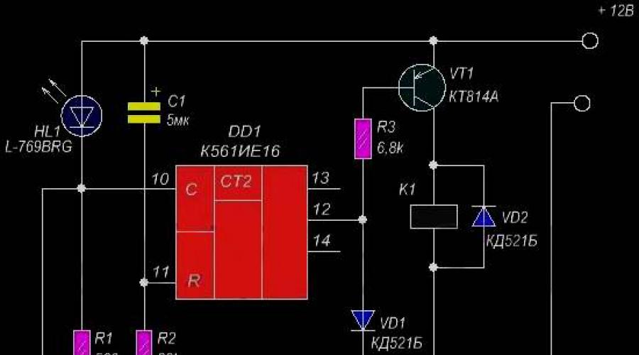
The design is made on only one chip K561IE16. Since, for its correct operation, an external clock generator is needed, in our case we will replace it with a simple blinking LED.
As soon as we apply power to the timer circuit, the capacitance C1 will start charging through the resistor R2 therefore, a logical one will briefly appear at pin 11, resetting the counter. The transistor connected to the meter output will open and turn on the relay, which will connect the load through its contacts.

With a flashing LED with a frequency 1.4 Hz pulses are sent to the clock input of the counter. With each pulse drop the counter counts. Through 256 pulses or about three minutes, a logical one level will appear at pin 12 of the counter, and the transistor will close, turning off the relay and the load switched through its contacts. In addition, this logical unit passes to the DD clock input, stopping the timer. The operating time of the timer can be selected by connecting point “A” of the circuit to various outputs of the counter.
The timer circuit is made on a microcircuit KR512PS10, which has in its internal composition a binary counter-divider and a multivibrator. Like a conventional counter, this microcircuit has a division coefficient from 2048 to 235929600. The selection of the required coefficient is set by applying logical signals to the control inputs M1, M2, M3, M4, M5.

For our timer circuit, the division factor is 1310720. The timer has six fixed time intervals: half an hour, an hour and a half, three hours, six hours, twelve hours and a day of an hour. The operating frequency of the built-in multivibrator is determined by the resistor values R2 and capacitor C2. When switch SA2 is switched, the frequency of the multivibrator changes, and passing through the counter-divider and the time interval.
The timer circuit starts immediately after turning on the power, or you can press the SA1 toggle switch to reset the timer. In the initial state, the ninth output will have a logical one level and the tenth inverse output will have a zero level, respectively. As a result of this, the transistor VT1 connects the LED part of the optothyristors DA1, DA2. The thyristor part has an anti-parallel connection, this allows you to regulate the alternating voltage.
Upon completion of the time countdown, the ninth output will set to zero and turn off the load. And at output 10 a unit will appear, which will stop the counter.
The timer circuit is launched by pressing one of three buttons with a fixed time interval, and it begins to count down. In parallel with pressing the button, the LED corresponding to the button lights up.

When the time interval expires, the timer emits a sound signal. A subsequent press will turn off the circuit. Time intervals are changed by the ratings of radio components R2, R3, R4 and C1.
Timer circuit, which provides a turn-off delay, is shown in the first figure. Here, a transistor with a p-type channel (2) is connected to the load power circuit, and a transistor with a n-type channel (1) controls it.

The timer circuit works as follows. In the initial state, capacitor C1 is discharged, both transistors are closed and the load is de-energized. When you briefly press the Start button, the gate of the second transistor is connected to the common wire, the voltage between its source and gate becomes equal to the supply voltage, it instantly opens, connecting the load. The voltage surge that appears on it through capacitor C1 is supplied to the gate of the first transistor, which also opens, so the gate of the second transistor will remain connected to the common wire even after the button is released.
As capacitor C1 is charged through resistor R1, the voltage on it increases, and on the gate of the first transistor (relative to the common wire) decreases. After some time, depending mainly on the capacitance of capacitor C1 and the resistance of resistor R1, it decreases so much that the transistor begins to close and the voltage at its drain increases. This leads to a decrease in the voltage at the gate of the second transistor, so the latter also begins to close and the voltage across the load decreases. As a result, the voltage at the gate of the first transistor begins to decrease even faster.
The process proceeds like an avalanche, and soon both transistors close, de-energizing the load, capacitor C1 quickly discharges through diode VD1 and the load. The device is ready to start again. Since the field-effect transistors of the assembly begin to open at a gate-source voltage of 2.5...3 V, and the maximum permissible voltage between the gate and source is 20 V, the device can operate with a supply voltage from 5 to 20 V (nominal voltage of capacitor C1 should be a few volts more than the supply). The shutdown delay time depends not only on the parameters of elements C1, R1, but also on the supply voltage. For example, increasing the supply voltage from 5 to 10 V leads to its increase by approximately 1.5 times (with the nominal values of the elements indicated in the diagram, it was 50 and 75 s, respectively).
If, with the transistors closed, the voltage across resistor R2 is more than 0.5 V, then its resistance must be reduced. A device that provides a switch-on delay can be assembled according to the circuit shown in Fig. 2. Here the transistors of the assembly are connected in approximately the same way, but the voltage to the gate of the first transistor and capacitor C1 is supplied through resistor R2. In the initial state (after connecting the power source or after pressing the SB1 button), capacitor C1 is discharged and both transistors are closed, so the load is de-energized. As R1 and R2 charge, the voltage across the capacitor rises, and when it reaches approximately 2.5 V, the first transistor begins to turn on, the voltage drop across R3 increases, and the second transistor also begins to turn on. When the load voltage increases so much that diode VD1 opens, the voltage across resistor R1 increases. This leads to the fact that the first transistor, and then the second one, opens faster and the device abruptly switches to the open state, closing the load power circuit
The timer circuit is a restart; to do this, you need to press the button and hold it in this state for 2...3 s (this time is enough to completely discharge capacitor C1). Timers are mounted on printed circuit boards made of fiberglass foil on one side, the drawings of which are shown in Fig. 3 and 4. The boards are designed for the use of diodes of the KD521, KD522 series and surface mounting parts (resistors R1-12, size 1206 and tantalum oxide capacitor). Setting up devices comes down mainly to selecting resistors to obtain the required time delay.
The described devices are designed to be included in the positive power supply wire of the load. However, since the IRF7309 assembly contains transistors with both channel types, the timers can easily be adapted to be included in the negative wire. To do this, the transistors should be swapped and the diode and capacitor switched on in reverse polarity (of course, this will require corresponding changes in the printed circuit board drawings). It should be taken into account that if the connecting wires are long or there are no capacitors in the load, interference on these wires and uncontrolled activation of the timer is possible. To increase noise immunity, a capacitor with a capacity of several microfarads with a rated voltage not less than the supply voltage must be connected to its output.
Five minute timer circuit |
If the time interval is more than 5 minutes, the device can be restarted and continue counting again.

After a short circuit of SВ1, capacitance C1, connected to the collector circuit of transistor VT1, begins to charge. The voltage from C1 is supplied to an amplifier with a high input resistance on transistors VT2-VT4. Its load is an LED indicator that turns on alternately every minute.
The design allows you to choose one of five possible time intervals: 1.5, 3, 6, 12 and 24 hours. The load is connected to the AC mains when the timing begins and is disconnected when the timing ends. Time intervals are set using a frequency divider of square wave signals generated by an RC multivibrator.
The master oscillator is made on the logical components DD1.1 and DD1.2 of the microcircuit K561LE5. The generation frequency is formed by an RC circuit on R1,C1. The accuracy of the stroke is adjusted over the shortest time interval, using the selection of resistance R1 (temporarily, when adjusting, it is advisable to replace it with a variable resistance). To create the necessary time ranges, pulses from the multivibrator output go to two counters DD2 and DD3, as a result of which the frequency is divided.
These two counters - K561IE16 are connected in series, but for simultaneous reset, the zeroing pins are connected together. Reset occurs using switch SA1. Another toggle switch SA2 selects the required time range.

When a logical one appears at the output of DD3, it goes to pin 6 of DD1.2, as a result of which the generation of pulses by the multivibrator ends. At the same time, the logical one signal goes to the input of the inverter DD1.3 to the output of which VT1 is connected. When a logical zero appears at the output of DD1.3, the transistor closes and turns off the LEDs of the optocouplers U1 and U2, and this turns off the triac VS1 and the load connected to it.
When the counters are reset, their outputs are set to zero, including the output to which switch SA2 is installed. A zero is also supplied at the input of DD1.3 and, accordingly, a unit at its output, which connects the load to the network. Also in parallel, the zero level will be set at input 6 of DD1.2, which will trigger the multivibrator and the timer will begin counting. The timer is powered using a transformerless circuit consisting of components C2, VD1, VD2 and C3.
When toggle switch SW1 is closed, capacitor C1 begins to slowly charge through resistance R1, and when the voltage level on it is 2/3 of the supply voltage, trigger IC1 will respond to this. In this case, the voltage at the third terminal will drop to zero, and the circuit with the light bulb will open.

With a resistance of resistor R1 of 10M (0.25 W) and capacitance C1 of 47 µF x 25 V, the operating time of the device is about 9 and a half minutes, if desired, it can be changed by adjusting the values of R1 and C1. The dotted line in the figure indicates the inclusion of an additional switch, with which you can turn on the circuit with the light bulb even when the toggle switch is closed. The design's quiescent current is only 150 μA. Transistor BD681 - compound (Darlington) medium power. Can be replaced with BD675A/677A/679A.
This is a timer circuit on a PIC16F628A microcontroller, borrowed from a good Portuguese site on radio electronics. The microcontroller is clocked from an internal oscillator, which can be considered quite accurate for this moment, since pins 15 and 16 remain free, you can use an external quartz resonator for even greater accuracy in operation.
With the help of electronic relays you can save money quite well, for example, let's take light in the corridor, storage room or entrance. By pressing the button, we turn on the light and after a certain time it automatically turns off. This time should be enough to search for the item in the hallway, closet, or get into the apartment. In addition, the lighting does not turn on unnecessarily if you forget to turn it off. This device is not only useful, but also very convenient. In this article we will tell you how to make a time relay with your own hands, providing all the necessary diagrams and instructions.
The simplest option
An example of a constructor for a homemade shutdown delay timer:
If desired, it is possible to independently assemble a time relay according to the following scheme:
The timing element is C1, in the standard configuration of the KIT set it has the following characteristics: 1000 µF/16 V, the delay time in this case is approximately 10 minutes. Time adjustment is carried out by variable R1. The board's power supply is 12 Volts. The load is controlled through relay contacts. You don’t have to make the board, but assemble it on a breadboard or mounted it.

In order to make a time relay, we need the following parts:

A correctly assembled device does not require configuration and is ready for use. This homemade time delay relay was described in the magazine “Radiodelo” 2005.07.
Homemade product based on NE 555 timer
Another electronic timer circuit for DIY assembly is also easy and easy to repeat. The heart of this circuit is the NE 555 integrated timer chip. This device is designed to both turn off and turn on devices; below is a diagram of the device:

NE555 is a specialized chip used in the construction of all kinds of electronic devices, timers, signal generators, etc. It is common enough that it can be found in any radio store. This microcircuit controls the load through an electromechanical relay, which can be used to both turn on and off the payload.
The timer is controlled by two buttons: “start” and “stop”. To start counting the time, you must press the “start” button. The device is turned off and returned to its original state using the “stop” button. The node that sets the time interval is a chain of variable resistor R1 and electrolytic capacitor C1. The value of the turn-on delay depends on their rating.

With the given values of elements R1 and C1, the time range can be from 2 seconds to 3 minutes. An LED connected in parallel to the relay coil is used as an indicator of the operating status of the structure. As in the previous circuit, its operation requires an additional 12 Volt external power source.
In order for the relay to turn on itself immediately when power is applied to the board, it is necessary to slightly change the circuit: connect pin 4 of the microcircuit to the positive wire, disconnect pin 7, and connect pins 2 and 6 together. You can learn more clearly about this scheme from the video, which describes in detail the process of assembling and working with the device:
Single transistor relay
The simplest option is to use a time relay circuit with just one transistor, KT 973 A, its imported analogue BD 876. This solution is also based on charging the capacitor to the supply voltage, through a potentiometer (variable resistor). The highlight of the circuit is the forced switching and discharge of the capacitance through resistor R2 and the return of the original initial position with toggle switch S1.
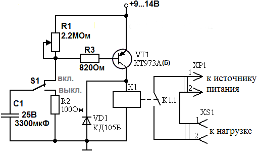
When power is applied to the device, capacitance C1 begins to charge through resistor R1 and through R3, thereby opening transistor VT1. When the capacitance is charged to the shutdown state of VT1, the relay is de-energized, thereby turning off or turning on the load, depending on the purpose of the circuit and the type of relay used.
The elements you select may have a slight variation in ratings; this will not affect the performance of the circuit. The delay may vary slightly and depend on the ambient temperature, as well as the magnitude of the mains voltage. The photo below provides an example of a finished homemade product:

Now you know how to make a time relay with your own hands. We hope the instructions provided were useful to you and you were able to assemble this homemade product at home!
Some people still use hourglasses to measure short periods of time. Watching the movement of grains of sand in such a watch is very exciting, but using it as a timer is not always convenient. Therefore, they are being replaced by an electronic timer, the diagram of which is presented below.
Timer circuit

It is based on the widely used inexpensive NE555 chip. The operating algorithm is as follows - when you briefly press the S1 button, a voltage equal to the circuit supply voltage appears at the OUT output and LED1 lights up. After a specified period of time, the LED goes out and the output voltage becomes zero. The timer operating time is set by trimming resistor R1 and can vary from zero to 3-4 minutes. If there is a need to increase the maximum delay time of the timer, then you can increase the capacitance of capacitor C1 to 100 μF, then it will be approximately 10 minutes. As transistor T1, you can use any bipolar transistor of medium or low power n-p-n structure, for example, BC547, KT315, BD139. Any button for closing without fixing can be used as button S1. The circuit is powered by a voltage of 9 - 12 volts, the current consumption without load does not exceed 10 mA.

Making a timer
The circuit is assembled on a printed circuit board measuring 35x65, the file for the Sprint Layout program is attached to the article. The trimmer can be installed directly on the board, or it can be wired and a potentiometer can be used to adjust the operating time. To connect power and load wires, the board has spaces for screw terminals. The board is made using the LUT method, several photos of the process:


Download the board:
(downloads: 251)
After soldering all the parts, the board must be cleaned of flux and the adjacent tracks must be checked for short circuits. The assembled timer does not need to be configured; all that remains is to set the desired operating time and press the button. A relay can be connected to the OUT output, in which case the timer can control a powerful load. When installing a relay in parallel with its winding, a diode should be installed to protect the transistor. The scope of application of such a timer is very wide and is limited only by the user’s imagination. Happy building!
A device that uses electronic and mechanical elements and operates after a certain period of time has passed is a time relay. These mechanisms have become widespread in many fields such as electronics, electrical and electrical engineering. To make a timer, you will have to use various schemes with varying degrees of complexity.
Principle of operation
 The presence of relays in a specific circuit allows you to assemble devices that are more flexible in controllability. Moreover, a large number of solutions can be implemented. Therefore, it is necessary to consider each design proposal separately. Depending on the type of activity performed, electromagnetic, electronic and pneumatic systems, as well as solutions for clock mechanisms, are used in practice.
Electromagnetic devices, as a rule, can only be used in circuits with a constant current source. The duration of action is usually 0.06−0.1 seconds. for turning on and 0.6−1.4 for turning off. Such relays contain two working layers of winding, one of them is a short-circuited ring-shaped circuit.
When electric current is applied to the first winding, the magnetic flux increases. It generates current in the second winding, as a result of which the growth of the main flux stops. As a result, a time characteristic of the displacement of the armature of the mechanism appears, and a time delay is formed.
If you stop supplying electric current to the circuit of the first winding, the magnetic field of the second winding will remain active for some time. All this happens due to the inductive effect. It follows from this that the relay does not turn off at this time.
Pneumatic and clock type
Schemes based on pneumatic systems are unique. These devices contain a special deceleration system - a pneumatic damper device. The holding time of the “pneumatics” can be adjusted by expanding or narrowing the cross-section of the pipe from which the air is supplied. For such an operation, a special adjusting screw is provided in the design.
 The time delay here ranges from 1–60 seconds. However, there are instances that work twice as fast. In reality, there are small errors in the indicated times.
Devices called clock relays are widely used in electrical applications. This type is actively used for the construction of automatic switches that protect circuits with a voltage of 500-10,000 volts. Response time - 0.1−20 sec.
The basis of clock relays is a spring, which is charged by an electromagnetic mechanical drive. The contact groups of the clock mechanism switch after a period of time has passed, specified in advance on a special scale of the device.
The speed of the device directly depends on the strength of the current passing in the winding. This helps configure the device for protective functions. The main feature of such protection is complete independence from the influence of external factors.
Electronic relays
Electronic relays have replaced outdated electromechanical devices. Such devices have many advantages:
- Small dimensions.
- Accuracy of action.
- Flexible configuration module.
- Reproduction of information.
The operation of electronic relays is based on the principle of digital pulse counters. A large number of today's devices are based on high-performance microprocessors.

To configure the electronic mechanism, you only need to set certain parameters using special function keys located on the front of the device. Moreover, the setting is flexible, that is, you can set not only seconds, minutes, hours, but also days of the week.
Weekly timer
An electronic on/off timer in automatic mode is used in various fields. A “weekly” relay switches within a predetermined weekly cycle. The device allows:
- Provide switching functions in lighting systems.
- Turn on/off technological equipment.
- Start/disable security systems.
The dimensions of the device are small, the design provides function keys. Using them, you can easily program the device. In addition, there is a liquid crystal display that displays information.
 Control mode can be activated by pressing and holding the “P” button. The settings are reset using the “Reset” button. During programming, you can set the date, the limit is a week. The time relay can operate in manual or automatic mode. Modern industrial automation, as well as various household modules, are most often equipped with devices that can be adjusted using potentiometers.
The front of the panel assumes the presence of one or more potentiometer rods. They can be adjusted using a screwdriver blade and set to the desired position. There is a marked scale around the stem. Such devices are widely used in control structures of ventilation and heating systems.
Instruments with mechanical scale
One of the devices that has a mechanical scale is a household timer. It works from a regular outlet. Such a device allows you to control home appliances within a certain time range. It contains a “socket” relay, which is limited by the daily operating cycle.
To use the daily timer it needs to be configured:
- Raise all the elements that are located along the disc circumference.
- Omit all elements that are responsible for setting the time.
- Scroll the disk and set it to the current time period.

For example, if the elements are omitted on the scale marked 9 and 14, then the load will be activated at 9 a.m. and will be turned off at 2 p.m. You can create up to 48 device activations per day.
In addition, the device has functionality that allows you to activate the timer in out-of-program mode.
To do this, you need to activate the button located on the side of the case. If you start it, the timer will start in urgent mode, even if it was turned on.
Mechanism activation
The device is connected in the strict position prescribed by the technical data sheet. Typically, the device is installed in a vertical position if it does not deviate from the vertical by more than 10 degrees. It is also necessary to adhere to the temperature regime: from -20 to +50 degrees Celsius.
The third parameter that is taken into account when installing the device is air humidity. The acceptable level should not be more than 80%. When connecting, it is necessary to disconnect the electrical circuit from the power supply device. Scheme of how to make a 220V time relay with your own hands:

Additionally, on the body itself there are symbols indicating in what sequence to connect the elements. It usually looks like this:
- First of all, connect the voltage line to the power terminals.
- Next, there is a connection between the phase line and the switch and input contact.
- The last step is to connect the output contact to the phase line.
In fact, the time relay is connected along the classic path of many devices, that is, the power is connected and the load is activated through the corresponding contacts that form groups, there are several of them. It all depends on the relay, which can be single-phase or three-phase.
Scheme for beginners
As a novice radio amateur, you can make a 12V time relay with your own hands. Such a mechanism will work according to the simplest principle.
Time relay connection diagram:

However, with such a device it will be possible to turn on the load for a certain time. But there is a small feature - the load time will always be the same.
The button labeled SB1 closes and C1 is fully charged. When the button is released, part C1 will be discharged through R1 and the base of the transistor, which is indicated in the diagram under the VT1 index.
While the capacitor is discharging, the current is sufficient to maintain the open state of transistor VT1, which means the relay will work, then turn off. Of course, you can make a time relay for 2 hours with your own hands - it all depends on the capacity of capacitor C1.
To ensure precise intervals of time when performing various actions using electrical equipment, time relays are used.
They are used everywhere in everyday life: electronic alarm clock, changing operating modes of a washing machine, microwave oven, exhaust fans in the toilet and bathroom, automatic watering of plants, etc.
Advantages of timers
Of all the varieties, electronic devices are the most common. Their advantages:
- small sizes;
- exceptionally low energy consumption;
- no moving parts except for the electromagnetic relay mechanism;
- wide range of time exposures;
- independence of service life from the number of operating cycles.
Transistor time relay
With basic electrician skills, you can make an electronic time relay with your own hands. It is mounted in a plastic case, which houses the power supply, relay, board and control elements.
The simplest timer
The time relay (diagram below) connects the load to the power supply for a period of 1-60 seconds. The transistor switch controls the electronic relay K1, which connects the consumer to the network with contact K1.1.

In the initial state, switch S1 closes capacitor C1 to resistance R2, which keeps it discharged. Electromagnetic switch K1 does not work in this case, since the transistor is locked. When the capacitor is connected to the power supply (upper position of contact S1), its charging begins. A current flows through the base, which opens the transistor and K1 turns on, closing the load circuit. The supply voltage to the time relay is 12 volts.
As the capacitor charges, the base current gradually decreases. Accordingly, the magnitude of the collector current drops until K1, by turning off, opens the load circuit with contact K1.1.
To reconnect the load to the network for a specified period of operation, the circuit must be restarted again. To do this, the switch is set to the lower "off" position, which leads to the discharge of the capacitor. The device is then turned on again by S1 for a specified period of time. The delay is adjusted by installing resistor R1, and can also be changed if the capacitor is replaced with another one.
The principle of operation of a relay using a capacitor is based on its charging for a time depending on the product of the capacitance and the resistance of the electrical circuit.
Timer circuit with two transistors
It is not difficult to assemble a time relay with your own hands using two transistors. It starts working if power is applied to capacitor C1, after which it will begin charging. In this case, the base current opens transistor VT1. Following it, VT2 will open, and the electromagnet closes the contact, supplying power to the LED. Its glow will indicate that the time relay has activated. The circuit provides load switching R4.
As the capacitor charges, the emitter current gradually decreases until the transistor turns off. As a result, the relay will turn off and the LED will stop working.

The device restarts if you press the SB1 button and then release it. In this case, the capacitor will discharge and the process will repeat.
Operation begins when the 12V time relay is energized. For this purpose, autonomous sources can be used. When powered from the network, a power supply consisting of a transformer, rectifier and stabilizer is connected to the timer.
Time relay 220v
Most electronic circuits operate at low voltage with galvanic isolation from the network, but can still switch significant loads.
The time delay can be made from a 220V time relay. Everyone knows electromechanical devices with a delay in turning off old washing machines. It was enough to turn the timer knob, and the device turned on the engine for a specified time.
Electromechanical timers have been replaced by electronic devices, which are also used for temporary lighting in the toilet, on the landing, in a photo enlarger, etc. In this case, contactless switches on thyristors are often used, where the circuit operates from a 220 V network.

Power is supplied through a diode bridge with a permissible current of 1 A or more. When the contact of switch S1 closes, in the process of charging capacitor C1, thyristor VS1 opens and lamp L1 lights up. It serves as a load. Once fully charged, the thyristor will close. This will be visible when the lamp turns off.
The lamp burns for a few seconds. It can be changed by installing capacitor C1 with a different value or connecting a 1 kOhm variable resistor to diode D5.
Time relay on microcircuits
Transistor timer circuits have many disadvantages: the difficulty of determining the delay time, the need to discharge the capacitor before the next start, and short response intervals. The NE555 chip, called the “integrated timer,” has long gained popularity. It is used in industry, but you can see many schemes for making time relays with your own hands.

The time delay is set by resistances R2, R4 and capacitor C1. The load connection contact K1.1 closes when the SB1 button is pressed, and then it opens independently after a delay, the duration of which is determined from the formula: t and = 1.1R2∙R4∙C1.
When you press the button again, the process repeats.
Many household appliances use microcircuits with time relays. Instructions for use are a necessary attribute of proper operation. It is also compiled for do-it-yourself timers. Their reliability and durability depend on this.
The circuit operates from a simple 12 V power supply consisting of a transformer, diode bridge and capacitor. The current consumption is 50 mA, and the relay switches a load of up to 10 A. The adjustable delay can be made from 3 to 150 s.
Conclusion
For domestic purposes, you can easily assemble a time relay with your own hands. Electronic circuits work well on transistors and microcircuits. You can set a contactless timer on thyristors. It can be turned on without galvanic isolation from the existing network.