Electronic caliper with depth gauge. How to use a caliper: step by step instructions How to take caliper readings
A review of a good, in my opinion, and almost completely metal (where possible) caliper.
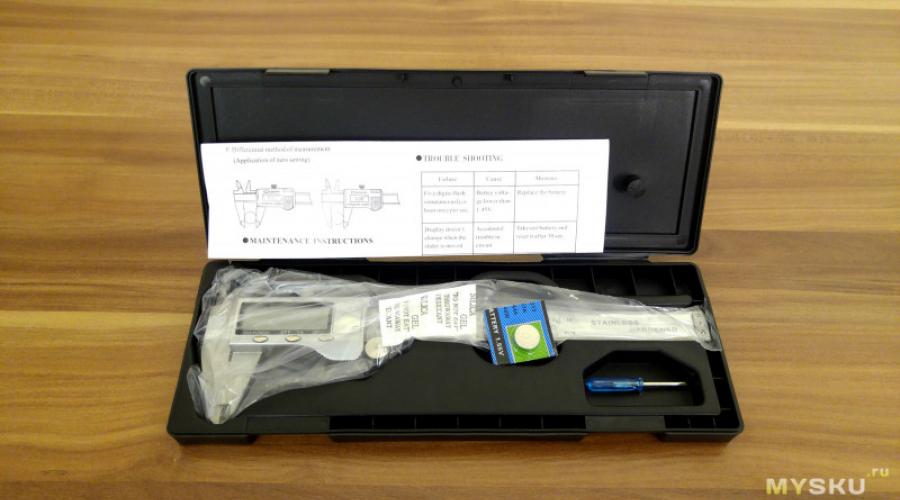
This tool comes in this box:

There are two batteries in the kit - one is already inserted into the caliper, the other is spare in a blister, type LR44 (AG13).
Here are a couple more photos of the caliper:


Metal is used wherever it is structurally and technically possible, even the battery cover is metal.
A little real specifications
and features (not from the instructions, from practice).
The maximum measured size is 154 mm.
Automatic inclusion at the beginning of the movement of a mobile part. In this case, the zero is stored correctly, where this zero was before switching off.
Automatic shutdown after 6 minutes of non-use.
There is a depth gauge, its zero is polished accurately.
Well, a few characteristics from the instructions:
Resolution and repeatability of the result: 0.01 mm.
Accuracy On Range< 100 мм: +-0.02 мм.
Accuracy On the range of 100 - 200 mm: +-0.03 mm.
The maximum speed of the slider movement, at which the controller has time to calculate the movement: 1.5 m/s.
Principle of operation.
A little about the principle of operation of such calipers. It is capacitive. There are no wheels that spin and measure the movement of the moving part. There is a control board located in the moving part, on which conductors are applied according to the type of risks in a conventional caliper and there are similar conductive risks on the ruler of the caliper. That is why the top plate with numbers and divisions on the rail is not metal, there are hidden risks in it. These risks are located at certain distances, and when moving relative to each other, the capacity at different risks changes in different ways, and the controller calculates these changes and, as a result, receives information about the amount of movement.
This is then displayed on the screen.
A little lower in the review there will be a disassembly of the caliper and you will see a board with risks.
The final result of the tool’s operation depends, in addition to the quality of manufacture of the material part of the caliper, including both the caliper glands themselves and the electronics used, especially its analog part, and also on the controller firmware, which calculates capacitance changes at risks and translates this into travel length.
Let's return from theory to practice.
Here are two small videos with a demonstration of the operation of a caliper:
Let's break it down now let's see what's inside.

Here is the same board with risks:

And here you can see the controller, buttons, and LCD screen:

Conclusion: During the test, I did not notice any problems in the operation of the caliper. The readings do not jump, multiple measurements of the same object give an error of no more than one hundredth. If you don't mind the money, I don't think it's a bad buy.
The product was provided for writing a review by the store. The review is published in accordance with clause 18 of the Site Rules.
I plan to buy +8 Add to favorites Liked the review +25 +39As you will see from this article, the modification of an electronic digital caliper is very simple procedure, but it must be done carefully so as not to damage the instrument. The design of the electronic caliper provides 4 special contacts. These contacts, for example, can be used to connect an external power supply, control functions, etc.

The pin assignments are (from left to right): negative terminal, data, clock, and positive terminal.
To activate the hidden options of the electronic digital caliper, pins 2 and 4 must be connected together.

Perhaps different electronic calipers have some differences, but in general, their modification is carried out in the same way.
The first step in finalization is to find the screws holding the case together. On our caliper they are located under plastic sticker. Their location can be seen in the photo.

After opening the plastic case containing the circuit board, display and several metal elements, you need to unscrew a few screws to remove printed circuit board.
Special care must be taken when handling the printed circuit board and the display.
The display is connected to the printed circuit board by means of a conductive rubber gasket. Be careful not to detach the display from the board, as this will make it difficult to align the connections during reassembly. And if the location is incorrect, the display may turn off spontaneously and strange characters appear on it.

After removing the printed circuit board of the electronic caliper, we get access to the necessary contacts.
Now you can solder 2 thin wires (the thinner the better). Solder one to pin number 2 and the other to pin number 4.

To close these terminals, it is best to use a micro button, for example, from an old computer mouse. The pins of the button need to be bent at a 90º angle (as in the picture) so that it fits snugly into the slot and therefore is held firmly in place.

After soldering the wires, the assembly of the electronic digital caliper is carried out in the reverse order. After assembly, soldered wires should stick out of the socket.
After that, solder the button and place it in the slot.

Because the button legs have been pre-bent, they spring the button and hold it firmly in place. Here's what it looks like.

By pressing a new button, we get access to some modes that were previously not available.
When the button is pressed for the first time, the electronic caliper enters the fast reading (FT) mode, when the ZERO button is pressed, we can freeze the measured value (H).

When the button is pressed again, the electronic caliper will enter the mode minimum value(MIN). In this mode, the display shows the smallest measured value.
If you press the "ZERO" button again, we will again switch to the mode of fixing the measured value (H).
 votes)
Do-it-yourself apartment renovation is always associated with the need to perform various measurements.
An ordinary ruler or tape measure cannot always provide the necessary accuracy, and in some cases it is simply impossible to use them.
The caliper is a professional measuring tool.
Our tips are designed to help the home master choose it for many types of measurements and marking work in everyday life. Short review industrial products a large assortment will allow you to more accurately determine necessary model according to its specifications.
The optimal choice is possible on the basis of taking into account:
- accuracy classes;
- measurement limits;
- convenience of use;
- simplicity of design;
- cost.
Purpose
Calipers of any model are designed to perform high-precision measurements of distances of three types:
- external dimensions;
- indents on internal cavities;
- indentations from the base surface.
A home master may need a caliper when:
- choice of drill diameter;
- at ;
- turning parts on a lathe;
- other repair work.
Design features
The caliper device is represented by three types of separate measuring devices that have general class accuracy and uniform measurement limits.

Their results are displayed on general scale rods and nonius.
Components of a caliper
Structurally, the mechanism consists of:
- base element - rods;
- moving part - frame with additional devices.
Barbell
All details are placed on it. It is made flat. metal rail with fixed jaws and millimeter scale.

Frame
Composite design with internal grooves - the movable frame moves along the bar. It has its own jaws, vernier scale and locking mechanism.

The fixation unit consists of a force adjustment screw with a spring-loaded plate that creates a uniform pressure when the frame moves along the entire length of the rod.

The working edges of the jaws of the frames and the rod have an angular sharpening. To perform external measurements, it is designed with restrictive stops, and internal - along the entire length of the working edge.

Measuring scales
The reading of the length of the measured part in mm is taken on the rod scale, and the subsequent refinement of their shares is performed using the vernier. Its accuracy class in mm is:
- 0,02;
- 0,05;

The vernier scale can be applied directly to the body of the movable frame, as shown in the bottom photo, or fastened with screws to perform accurate calibration of the instrument - top picture.
How vernier scales and barbells work
Let's look at the example of a caliper with an accuracy class of 0.1.

The price of one division of the rod, located on top, is exactly 1.0 mm, and for the nonius - 1.9. Therefore, its ten lower divisions occupy 19 mm.
For all measurements, the zero position of the vernier scale, set opposite the upper divisions, is used as an indicator of the size of the measured part. In the figure shown, it is located at the origin of the rod and indicates 0 mm in length.
During the measurement, the movable frame moves along the rod, moving away from the beginning of the scale, and is fixed in a certain position, for example, as shown in the figure below.

The zero of the vernier scale passed two millimeters along the bar. It indicates the integer part of the measured number - 2.0 mm. Of all the other nine marks of the movable frame, the fourth one came closest to the upper calibrated divisions. It also shows the value of the fractional part - 0.4 mm.
It remains only to add them: 2.0 + 0.4 = 2.4 mm. We received the measurement result of the caliper in its accuracy class.
Design overview
All models of calipers can be divided into two types measuring device:
- mechanical with scales;
- digital with display.
Calipers of mechanical design
This type includes devices of the brands ShTs-1, ShTs-2, ShTs-3, ShTs-K.
Model ShTs-1

The simplest and most common brand of vernier caliper with a vernier scale type. The typical division value is 0.1 mm. But there are devices for 0.05 and 0.02.
Model ShTs-2
The device differs from the previous one by the presence of an additional frame with a locking screw and a regulating mechanism, as well as a special design of the jaws.

Them Bottom part allows you to measure both external and inner dimensions two different work surfaces. The reading difference between them in mm is marked directly on the case.

The protrusion line of the outer jaws is strictly parallel to the axis of the rod. This allows them to focus base surface part to be measured: increased accuracy is created.
The upper jaws are pointed and perform two tasks:

Model ShTs-3
The device completely repeats the design of the previous one, but it lacks the upper pair of marking and measuring jaws.

ШЦ-2 and ШЦ-3 are created with rods that allow measuring rather extended parts.
Model ShCK-1
Mechanism for counting fractions mm completed mechanical device with a dial. These devices provide the most high class accuracy in its group: 0.02 or even 0.01 mm.

To move the movable frame during measurements, a rack and pinion gear is used, controlled by the rotation of the handle wheel. The head is also fixed with a locking screw.

The disadvantages of this model include the need to maintain its rack and pinion mechanism of the rod and frame in constant cleanliness.
Calipers with digital display
One of the representatives of this class is the ShTsTs-1 model.

The additional letter "C" in the marking indicates the operation of the measuring device according to digital technology. This greatly simplifies the reading. SCC-1 has the most high precision: class 0.01.
As with all similar devices, there are control buttons here. different modes and offline source power supply located in a special compartment.
Thinking about the quality of work with such meters, you should not forget about all the shortcomings inherent in electronic devices:
- sensitivity to external electromagnetic fields;
- limited battery life, which is also sharply reduced at cold temperatures;
- the need for protection from moisture and mechanical stress;
- increased cost.
Electronic devices in the non-working position are kept in special cases. To measure the dimensions of the parts, they are removed and then put back in the same place. They require more careful handling than simple mechanical counterparts.
Checking serviceability and preparing for measurement
The measurement accuracy of any caliper depends on its technical condition. Examination metrological characteristics professional devices is carried out by specialists of the relevant laboratories.
For home master such an operation is redundant. It is enough to check the calibration certificate when buying and then keep your instrument in good condition.
However, one should take into account the possibility of its falls, bumps and other unforeseen cases. To this end, it is important to periodically carry out three simple rules health checks:
- examination of the external condition;
- zero reading check;
- assessment of the quality of measuring surfaces.
Visual inspection
They evaluate “by eye” the quality of the geometry of all parts, the cleanliness of surfaces, the need for lubrication with light oils of the grooves, the condition of the scales and the convenience of reading them. Check the ease of movement of moving parts.
Revealed minor defects can be removed by hand.
Checking the zero reading
The movable frame is shifted all the way to the initial position and the following is observed:
- setting both scales to zero;
- the location of the tenth division of the vernier at around 19 mm of the rod scale reading (for ShTs-1 accuracy class 0.1, as shown in the diagram above).
Quality assessment of measuring surfaces
The shifted sponges are placed towards the light source and visually assess the tightness of their fit. The picture above shows a similar test of one surface with a reference square.

Light rays will penetrate through the defective slots and indicate their location.
Pay attention to the position of the depth gauge. In the shifted state, it should be in the same plane with the far end of the rod.

To do this, it is pulled out when the end of the rod is installed on the reference plane and the measurement is taken on the reference scale. Must be 0.

Measurement techniques
It is important to understand: no caliper measures the part itself. It simply displays the position of the moving frame scale relative to the origin in a certain accuracy class. A person is engaged in measurements and quite often it is he who makes serious mistakes.
Measurements of external distances
The planes of the working surfaces of the caliper must be tightly brought to the measured part.

Its axis should be perpendicular to them.

To eliminate the measurement error helps to tilt the body on the measurement surface until it stops with a rod or use special protrusions on the jaws.

On long workpieces, the surface of the part should be parallel to the axis of the caliper rod.

Measurements of internal distances

The jaws of the caliper must fit snugly against inner surface and lie in a perpendicular plane.

Depression definition
All the rules described above also apply here. The photo below shows one of common mistakes when the deviation of the meter from a plane parallel to the surface of the part being measured is violated.

For exact definition recesses are necessary:
- ensure the correct stop of the end of the rod in the base plane;
- pull out the movable frame, firmly pressing the end of the pointer to the remote surface;
- ensure its shortest distance to the measurement point with a parallel orientation relative to the surface of the part;
- fix the locking screw;
- take the count correctly.
We hope that a small review and quick tips articles will help you choose and buy a caliper of the model that is more suitable for its characteristics. And now we will give a photo of the ShTs-1 model with a length of 160 cm and a class of 0.1 mm, which has been working in the arsenal of the author's tools for the third decade.

Most often it is used for:

At one time there was a passion for turning woodwork and for them I had my own hands. That's when the caliper was used very often.
Then I had to replace the drill with a . But after that, interest in turning work somehow faded away, and the machine was idle ...
As personal practice has shown, an accuracy class of 0.1 mm is quite enough for doing homework, and if you follow the operating rules, then such a device works for a very long time and reliably.
Although someone will find this clearly insufficient and there will be a desire to buy an electronic caliper ShTsTs-1 with a class of 0.01 mm for their needs. Decide for yourself.
Ask questions in the comments, share the read material with friends on social networks.
The main task of the caliper is to measure dimensions. The device, although simple, nevertheless allows you to measure almost any object with high accuracy. It finds application everywhere - from workshops of all directions to beauty salons (it is used, for example, to create perfect shape eyebrows).
Device
If you look at the photo of the caliper, it becomes obvious that the main elements of the device are typical for any of its types:
- Ruler - bar
- Jaws for measuring the outside and inside of a part
- Depth Gauge - additional option allows you to measure the depth of holes and grooves
- Nonius - an additional movable scale that allows you to measure with an accuracy of tenths of a millimeter (up to 0.05 mm, greater accuracy no longer makes sense, since the human eye will not make out the measurement result)
- Screw for fixing the measurement

The length of the rod of the device is 15 cm, but there are also specific models with a longer ruler.

The tips on the jaws are made of very hard metal, which allows them to be used also for marking (you can simply draw lines on the surface of plates, parts, etc.).


Measurement scheme
Let's take a closer look at how to use a caliper. First you need to decide on the nature of the measurements, and depending on whether the internal, external part or the depth of the product will be measured, desired element device, the principle of measurement is the same in all cases, so let's consider the example of measuring the outer part of the part:

The sponges are spread apart, the object is placed between them and the sponges are connected (if the object is hard, then the lips can be squeezed well, if a soft object is measured, then the main thing is not to crush the part, otherwise the measurement result will be incorrect). To make it convenient to take the measurement, the result can be fixed with a fixing screw.

The resulting values are checked on the ruler.

Since the number may not be an integer, it is necessary to pay attention to the vernier to determine the shares. First of all, you need to find a division that coincides with the division of the main ruler (for example, the main ruler gave a result of 2 cm and 4 millimeters “with kopecks”, to calculate “kopecks” we see that the risk 7 on the vernier coincided with the risk on the main ruler, so it turns out result 2.47 cm).

Important! Only 1 risk must match. If several risks match (zeros are not meant), then this device should not be used, as it is not working.


Varieties of calipers
All types of calipers are given in GOST 166-89. The most common nonius, dial and digital.

Nonius caliper
The device in the form in which we are accustomed to seeing it, and it was his device that was described above.

Dial caliper
An alternative to the vernier and ruler is the dial, the arrow immediately shows the measurement result. It is much easier to use, since you do not need to do vernier calculations. Achilles' heel in dial calipers - this is glass, if it breaks, the device is no longer suitable. But now on the shelves there are SCCs with a more durable carbon fiber board.


digital caliper
On the bar with divisions there is a carriage with an LCD display, where the received measurement data with a caliper is automatically displayed. They can be converted from millimeters to inches and vice versa at the touch of a button, and there is an additional button for saving measurements and resetting them to zero.

An electronic caliper is good for accuracy, clarity and speed of measurement; the movement of the jaws is more smoothly adjusted in it. And, you see, it is more convenient to look at the numbers than to try, straining your eyes, to catch the divisions.

Care and storage
The caliper belongs to the category of high-precision instruments. Therefore, it requires careful care. The presence of dirt or paint on it is unacceptable, as this will critically spoil the measurement readings.


A quality caliper is a guarantee good result production.


Photo of using a caliper


Determination of indications by vernier
To determine the readings of the caliper, it is necessary to add the values of its main and auxiliary scales.
- The number of whole millimeters is counted on the rod scale from left to right. The zero stroke of the vernier serves as the pointer.
- To count fractions of a millimeter, it is necessary to find that stroke of the vernier, which most closely matches one of the strokes of the main scale. After that, you need to multiply the serial number of the found vernier stroke (not counting zero) by the division value of its scale.
The measurement result is equal to the sum of two quantities: the number of whole millimeters and fractions of a mm. If the zero stroke of the vernier exactly coincided with one of the strokes of the main scale, the resulting size is expressed as an integer.
The figure above shows the readings of the ShTs-1 caliper. In the first case, they are: 3 + 0.3 = 3.3 mm, and in the second - 36 + 0.8 = 36.8 mm.
The scale of the device with a division value of 0.05 mm is presented below. For example, two different indications are given. The first is 6 mm + 0.45 mm = 6.45 mm, the second is 1 mm + 0.65 mm = 1.65 mm.

Similarly to the first example, it is necessary to find the strokes of the vernier and the rod, which exactly coincide with each other. In the figure, they are highlighted in green and black, respectively.
Mechanical caliper device
The device of a double-sided caliper with a depth gauge is shown in the figure. The measuring range of this tool is 0-150mm. With it, you can measure both external and internal dimensions, the depth of holes with an accuracy of 0.05 mm.

Main elements
- Barbell.
- Frame.
- Sponges for external measurements.
- Sponges for internal measurements.
- Depth gauge line.
- Locking screw for fixing the frame.
- Nonius scale. Used to read fractions of millimeters.
- Barbell scale.
Sponges for internal measurements 4 have a knife-like shape. Thanks to this, the size of the hole is determined by the scale without additional calculations. If the jaws of the caliper are stepped, as in the ShTs-2 device, then when measuring grooves and holes, their total thickness must be added to the readings obtained.
Nonius reading value y various models tool may vary. So, for example, for ShTs-1 it is 0.1 mm, for ShTs-II it is 0.05 or 0.1 mm, and the accuracy of devices with a vernier reading of 0.02 mm approaches the accuracy of micrometers. Design differences in the device of calipers can be expressed in the form of a movable frame, measurement limits, for example: 0–125 mm, 0–500 mm, 500–1600 mm, 800–2000 mm, etc. Measurement accuracy depends on various factors: vernier count values, work skills, good condition of the instrument.
Measurement procedure, serviceability check
Check before work technical condition caliper and adjust if necessary. If the device has skewed jaws, it must not be used. Also nicks, corrosion and scratches on working surfaces are not allowed. It is necessary that the ends of the rod and the depth gauge ruler coincide with the combined jaws. The scale of the instrument must be clean and legible.
Measurement
- The jaws of the caliper are pressed tightly with little effort, without gaps and distortions, to the part.
- When determining the outer diameter of the cylinder (shaft, bolt, etc.), make sure that the plane of the frame is perpendicular to its axis.
- When measuring cylindrical holes, the jaws of the caliper are placed at diametrically opposite points, which can be found by focusing on the maximum scale readings. In this case, the plane of the frame must pass through the axis of the hole, i.e. measurement along a chord or at an angle to the axis is not allowed.
- To measure the depth of a hole, the bar is placed at its edge perpendicular to the surface of the part. The depth gauge ruler is pushed all the way to the bottom using a movable frame.
- The resulting size is fixed with a locking screw and the readings are determined.
Working with a caliper, monitor the smoothness of the frame. It should sit tightly, without swaying, on the bar, while moving without jerking with a moderate effort, which is regulated by a locking screw. It is necessary that when the jaws are combined, the zero stroke of the vernier coincides with the zero stroke of the rod. Otherwise, reinstallation of the vernier is required, for which its fastening screws to the frame are loosened, the strokes are combined and the screws are re-fastened.