DIY electromagnetic rail gun. DIY gauss gun. How does a Gauss gun work?
Read also
I offer a diagram and description of the assembly of a simple single-stage electromagnetic accelerator (Gauss gun) powered from the mains. In a single-stage accelerator, the energy of the projectile depends on many parameters, such as its mass and diameter, the energy of the capacitors, the presence of a magnetic circuit, the material of the projectile, etc. Our accelerator will have a capacitor energy of no more than 40 J, and a projectile energy of less than 1 J.
Required parts:
Capacitors 470uF 450V -3 pieces
Power thyristor 70TPS12 or 40TPS12 - 1 piece
Resistors for ballast 6.2K - 8 pieces
And also 3 LEDs, 2 buttons, 1 power switch, diode, any voltmeter and a couple of meters of wire.
About the coil separately. It is wound with 0.6mm wire. Each layer must be impregnated with cyanoacrylic glue. Total 7 layers 40mm long. Dangles on plastic tube 7-8mm in diameter, a ballpoint pen tube is perfect.
Projectile- a piece of nail that moves freely along a 30mm long trunk.
Scheme:
Through the resistive ballast and the rectifier diode, capacitors C1-C4 are charged. Ballast is necessary because at the initial moment of charging, the resistance of the capacitors is almost zero. When connected directly to the network, the load on the conductors will be equal to the load short circuit, which will lead to burnout of connections and tripping of short-circuit protection (if any) in the power supply distributor.
Switch SA1 makes the device ready. The SB1 button charges the storage devices, the degree of which is controlled by the voltmeter readings. LED HL1 indicates the presence of a connection to the network, HL2 indicates the readiness of the device, HL3 indicates the charge of the storage devices.
The SB2 button fires a shot by connecting a 1.5V battery to the control terminal of the power thyristor VS1. When voltage is applied to the control electrode relative to the anode, the thyristor opens and closes the capacitors with the coil. When current flows in the coil, a magnetic field is created, which draws in the projectile. When the projectile is in the middle of the coil, the energy stored in the capacitors ends, the magnetic field stops, and the projectile continues to move.
Assembly Features:
Personally, I assemble such circuits not with a board, but by connecting them with wires, because the circuit is simple, but the parts are large. Capacitors, thyristor and coil must be connected with a conductor with a diameter of at least 1 mm; pulse currents can reach 300-400A.

With the assembled accelerator, I performed at technical creativity competitions. Both times I took first place.
List of radioelements
| Designation | Type | Denomination | Quantity | Note | Shop | My notepad |
|---|---|---|---|---|---|---|
| VS1 | Thyristor | 70TPS12 | 1 | 40TPS12 | To notepad | |
| Rectifier diode | HER307 | 1 | To notepad | |||
| HL1-HL3 | Light-emitting diode | AL307BM | 3 | To notepad | ||
| C1-C4 | Electrolytic capacitor | 470uF 450V | 4 | To notepad | ||
| Resistor | 30 kOhm | 3 | 0.5 W | To notepad | ||
| Resistor | 6.2 kOhm | 6 | 1 W | To notepad | ||
| Coil | Inductor | 1 |
Quite a powerful model of the famous Gauss cannon, which you can make with your own hands from available materials. This homemade Gauss gun is very easy to make and has lightweight design, all the parts used will be available to every DIY enthusiast and radio amateur. Using the coil calculation program, you can get maximum power.
So, to make a Gauss Cannon we need:
- A piece of plywood.
- Sheet plastic.
- Plastic tube for muzzle ∅5 mm.
- Copper wire for coil ∅0.8 mm.
- Large capacity electrolytic capacitors
- Start button
- Thyristor 70TPS12
- Batteries 4X1.5V
- Incandescent lamp and socket for it 40W
- Diode 1N4007
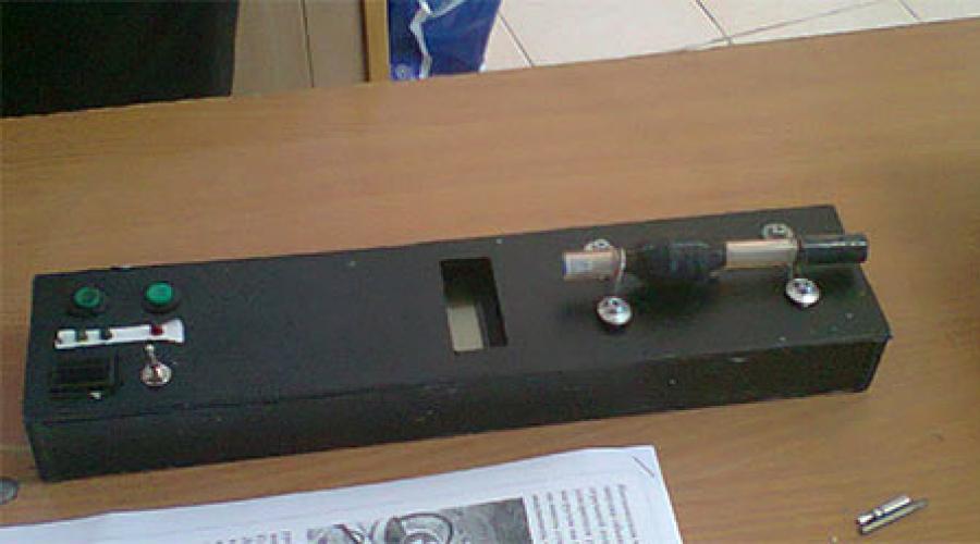
Assembling the housing for the Gauss gun circuit
The body shape can be any, it is not necessary to adhere to the presented scheme. To give the body an aesthetic appearance, you can paint it with spray paint.


Installing parts into the housing for the Gauss Cannon
First, we attach the capacitors, in in this case they were attached to plastic ties, but you can come up with another mount.

Then install the socket for the incandescent lamp on outside housings. Don't forget to connect two wires to it for power.


Then we place the battery compartment inside the case and fix it, for example, with wood screws or in another way.

Winding a Coil for a Gauss Gun
To calculate a Gaussian coil, you can use the FEMM program; you can download the FEMM program from this link https://code.google.com/archive/p/femm-coilgun
Using the program is very easy, you need to enter the necessary parameters in the template, load them into the program and at the output we get all the characteristics of the coil and the future gun as a whole, right down to the projectile speed.
So let's start winding! First you need to take the prepared tube and wrap paper on it using PVA glue so that the outer diameter of the tube is 6 mm.


Then we drill holes in the center of the segments and place them on the tube. Using hot glue we fix them. The distance between the walls should be 25 mm.


We place the coil on the barrel and proceed to the next stage...

Scheme of Gauss Cannon. Assembly

We assemble the circuit inside the case using hinged mounting.

Then we install the button on the body, drill two holes and thread the wires for the coil there.

To simplify use, you can make a stand for the gun. In this case it was made from wooden block. In this version of the carriage, gaps were left along the edges of the barrel, this is necessary in order to adjust the coil, moving the coil, you can achieve the greatest power.

Cannon shells are made from a metal nail. The segments are made 24 mm long and 4 mm in diameter. Shell blanks need to be sharpened.


So, let's look at everything in order. Charging the gun operates on a 220 volt network. Charging consists of a 1.5 uF 400 V capacitor. 1N4006 diodes. Output voltage 350 V.

Next comes the current-limiting load - H1, in my case an incandescent lamp, but you can use a powerful resistor of 500 - 1000 Ohms. Key S1 limits the charging of capacitors. Key S2 delivers a powerful discharge of current to the solenoid, so S2 must withstand high current, in my case I used the button from the electrical panel.

Capacitors C1 and C2, each 470 µF 400 V. The total is 940 µF 400 V. The capacitors must be connected observing the polarity and voltage on them during charging. You can control the voltage on them with a voltmeter.

And now the most difficult thing in our Gauss gun design is the solenoid. It is wound on a dielectric rod. The inner diameter of the trunk is 5-6 mm. The wire used PEL 0.5. The thickness of the coil is 1.5 cm. The length is 2 cm. When winding the solenoid, you need to insulate each layer with super glue.

We will accelerate our electromagnetic gauss gun with cuttings of nails or homemade bullets 4-5 mm thick and as long as a reel. Lighter bullets travel longer distances. Heavier ones fly a shorter distance, but they have more energy. My gauss gun penetrates beer cans and shoots at 10-12 meters depending on the bullet.

And also, for the accelerator it is better to select thicker wires so that there is less resistance in the circuit. Be extremely careful! During the invention of the accelerator, I was shocked several times, follow the electrical safety rules and pay attention to the reliability of insulation. Good luck with your creativity.
Discuss the article GAUSS GUNS
Hello. Today we will build a Gauss cannon at home using parts that can easily be found in local stores. Using capacitors, a switch and some other parts, we will create launcher, capable of launching small nails up to a distance of approximately 3 meters using electromagnetism. Let's get started!
Step 1: Watch the video
Watch the video first. You will study the project and see the gun in action. Read on to explore more detailed instructions assembly of the Gauss Gun device.
Step 2: Gathering the necessary materials

For the project you will need:
- 8 large capacitors. I used 3,300uF 40V. The key point The point here is that the lower the voltage, the less danger, so look for options in the region of 30 - 50 Volts. As for capacity, the more the better.
- One high current circuit breaker
- One coil of 20 turns (I twisted mine from 18awg wire)
- Copper sheet and/or thick copper wire
Step 3: Glue the capacitors together

Take the capacitors and glue them together so that the positive terminals are closer to the center of the glue. First glue them into 4 groups of 2 pieces. Then glue two groups together, resulting in 2 groups of 4 capacitors. Then place one group on top of the other.
Step 4: Assembling a group of capacitors

The photo shows what the final design should look like.
Now take the positive terminals and connect them to each other and then solder them to the copper pad. The overlay can serve as a thick copper wire or leaf.
Step 5: Solder the copper pads

Use directed heat if necessary (a small industrial hair dryer), heat the copper strips and solder the capacitor terminals to them.
The photo shows my group of capacitors after completing this step.
Step 6: Solder the Negative Terminals of the Capacitors

Take another thick conductor, I used an insulated copper lead with a large cross-section, removing it in in the right places isolation.
Bend the wire so that it covers the entire distance of our group of capacitors as efficiently as possible.
Solder it in the right places.
Step 7: Prepare the projectile

Next you need to prepare a suitable projectile for the reel. I wound my reel around the bobbin. I used a small straw as a muzzle. Therefore, my projectile must fit into the straw. I took the nail and cut it to about 3cm long, leaving the sharp part.
Step 8: Find a suitable switch

I then needed to find a way to dump the charge from the capacitors onto the coil. Most people use rectifiers (SCRs) for such needs. I decided to take a simpler approach and found a switch that worked when high strength current
There are three current ratings on the switch: 14.2A, 15A, and 500A. My calculations showed a maximum force of about 40A at a peak lasting about a millisecond, so it should have worked.
THE NOTE. Do not use my switching method if your capacitors are larger. I pressed my luck and everything worked out fine, but you don't want a breaker to blow because you ran 300A through a breaker rated for 1A.
Step 9: Winding the Reel

We are almost finished assembling the electromagnetic gun. Time to wind the reel.
I tried three different coils and found that about 20 turns of 16 or 18 awg insulated wire worked best. I used an old bobbin, wrapped some wire around it and threaded a plastic straw through it, sealing one end of the straw with hot glue.
Step 10: Assembling the device according to the diagram


Now that you have all the pieces ready, put them together. If you have any problems, follow the diagram.
Step 11: Fire Safety


Congratulations! We made the Grasse cannon with our own hands. Use a charger to charge your capacitors to almost maximum voltage. I charged my 40V setup to 38V.
Load the projectile into the tube and press the button. The current will flow to the coil and it will shoot a nail.
BE CAREFUL! Even considering that this is a low-current project and that it will not kill you, such current can still harm your health. The second photo shows what happens if you accidentally connect plus and minus.
Hello friends! Surely some of you have already read or personally encountered the Gauss electromagnetic accelerator, which is better known as the “Gauss Gun”.
A traditional Gauss gun is built using hard-to-find or rather expensive high-capacity capacitors, and also requires some wiring (diodes, thyristors, etc.) to properly charge and fire. This can be quite difficult for people who do not understand anything about radio electronics, but the desire to experiment does not allow them to sit still. In this article I will try to talk in detail about the principle of operation of the gun and how you can assemble a Gauss accelerator simplified to the minimum.
The main part of the gun is the coil. As a rule, it is wound independently on some kind of dielectric non-magnetic rod, whose diameter is slightly larger than the diameter of the projectile. In the proposed design, the coil can even be wound “by eye”, because the operating principle simply does not allow any calculations to be made. It is enough to extract copper or aluminum wire with a diameter of 0.2-1 mm in varnish or silicone insulation and wind 150-250 turns on the barrel so that the winding length of one row is approximately 2-3 cm. You can also use a ready-made solenoid.


When passing electric current A magnetic field arises through the coil. Simply put, the coil turns into an electromagnet that draws in the iron projectile, and in order for it not to remain in the coil, as it enters the solenoid, you simply need to turn off the current supply.
In classic guns this is achieved through precise calculations, the use of thyristors and other components that will “cut” the pulse into right moment. We will simply break the chain “when it works out.” For emergency tearing electrical circuit In everyday life, fuses are used; they can be used in our project, but it is more advisable to replace them with light bulbs from a Christmas tree garland. They are designed for food low voltage, therefore, when powered from a 220V network, they instantly burn out and break the circuit.


Finished device consists of only three parts: coils, network cable and a light bulb connected in series with the coil.

Many will agree that using a gun in this form is extremely inconvenient and unaesthetic, and sometimes even very dangerous. So I mounted the device on a small piece of plywood. I installed separate terminals for the coil. This makes it possible to quickly change the solenoid and experiment with different options. For the light bulb I installed two thin cut nails. The ends of the light bulb wires simply wrap around them, so the light bulb changes very quickly. Please note that the flask itself is located in a specially made hole.

The fact is that when a shot is fired, a large flash and sparks occur, so I considered it necessary to move this “stream” down a little.


The projectile's ejection speed here is quite high, but it even penetrates paper with difficulty; sometimes iron bullets are driven into the foam.

If you wish, you can watch my video for this