Color codes for phase L, zero N and ground. Color of wires phase, zero, ground Value of n in electrics
Read also
In most modern cables, the conductors are insulated different colors. These colors have a certain meaning and are chosen for a reason. What is color marking of wires and how to use it to determine where the zero and ground are, and where the phase is, and we will talk further.
In electrical engineering, it is customary to distinguish wires by color. This makes the work much easier and faster: you see a set of wires of different colors and, based on the color, you can guess which one is intended for what. But, if the wiring is not factory-made and you did not do it, before starting work you should definitely check whether the colors correspond to the intended purpose.
To do this, take a multimeter or tester, check the presence of voltage on each conductor, its magnitude and polarity (this is when checking the power supply network) or simply call where and where the wires come from and whether the color changes “along the way.” So knowledge color coding wiring is one of the essential skills of a home handyman.
Ground wire color coding
By latest rules Wiring in a house or apartment must be grounded. Last years All household and construction equipment are produced with a grounding wire. Moreover, the factory warranty is maintained only if the power supply is supplied with a working grounding.
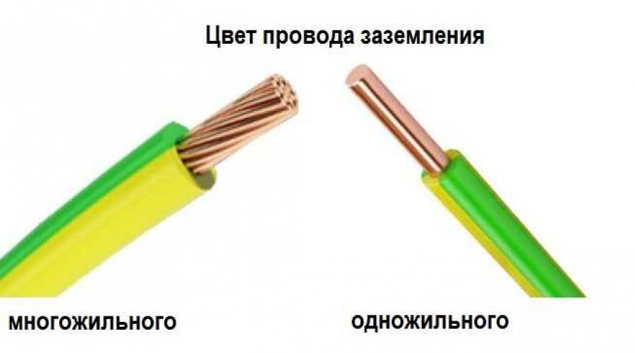
To avoid confusion, it is customary to use a yellow-green color for the ground wire. Hard solid wire has a green base color with a yellow stripe, and a soft stranded base color yellow color with a green longitudinal stripe. Occasionally there may be specimens with horizontal stripes or just green, but this is not standard.

Ground wire color - single-core and stranded
Sometimes the cable only has a bright green or yellow wire. In this case, they are used as “earthen”. On diagrams, “ground” is usually drawn green. On the equipment, the corresponding contacts are signed in Latin letters PE or in the Russian version they write “earth”. Often added to inscriptions graphic image(in the picture below).

In some cases, in the diagrams, the ground bus and the connection to it are indicated in green
Neutral color
Another conductor that is highlighted in a certain color is neutral or “zero”. The color blue is allocated for it (bright blue or dark blue, occasionally blue). On color diagrams, this circuit is also drawn in blue and signed with the Latin letter N. The contacts to which the neutral must be connected are also signed.

Neutral color - blue or light blue
Cables with flexible stranded wires typically use more light shades, and single-core rigid conductors have a sheath of darker, richer tones.
Coloring phase
With phase conductors it is somewhat more complicated. They are painted in different colors. Already used ones - green, yellow and blue - are excluded, and all others can be present. When working with these wires, you need to be especially careful and attentive, because they are the ones where voltage is present.

Color marking of wires: what color is the phase - possible options
So, the most common color markings for phase wires are red, white and black. There may also be brown, turquoise orange, pink, purple, gray.
On diagrams and terminals, phase wires are signed with the Latin letter L; in multiphase networks, the phase number is next to it (L1, L2, L3). On cables with several phases, they have different colors. This makes wiring easier.
How to determine if the wires are connected correctly
When trying to install an additional outlet, connect a chandelier, or household appliances, you need to know which wire is phase, which is neutral, and which is ground. At incorrect connection equipment breaks down, and careless touching of live wires can end sadly.

You need to make sure that the colors of the wires - ground, phase, zero - match their wiring
The easiest way to navigate is by color coding of the wires. But it's not always simple. Firstly, in old houses the wiring is usually monochromatic - two or three white or black wires stick out. In this case, you need to understand it specifically, and then hang tags or leave colored marks. Secondly, even if the conductors in the cable are painted in different colors, and you can visually find the neutral and ground, you need to check the correctness of your assumptions. It happens that during installation the colors are mixed up. Therefore, first we double-check the correctness of the assumptions, then we begin work.
To check you will need special tools or measuring instruments:
- indicator screwdriver;
- multimeter or tester.
You can find the phase wire using an indicator screwdriver; to determine zero and neutral, you will need a tester or multimeter.
Checking with indicator
Indicator screwdrivers come in several types. There are models on which the LED lights up when a metal part touches live parts. In other models, checking requires an additional button press. In any case, when voltage is present, the LED lights up.

Using an indicator screwdriver you can find the phases. We touch the exposed conductor with the metal part (press the button if necessary) and see if the LED lights up. Lit - this is a phase. Does not light - neutral or ground.
We work carefully, with one hand. Second to the walls or metal objects(pipes, for example) we don’t touch. If the wires in the cable you are testing are long and flexible, you can hold the insulation with your other hand (stay away from bare ends).
Checking with a multimeter or tester
We set the scale on the device, which is slightly higher than the expected voltage in the network, and connect the probes. If we call a household single-phase 220V network, set the switch to the 250V position. With one probe we touch the exposed part of the phase wire, with the second - to the supposed neutral ( of blue color). If at the same time the arrow on the device deviates (remember its position) or a number close to 220 V lights up on the indicator. We perform the same operation with the second conductor - which is identified by color as “ground”. If everything is correct, the readings of the device should be lower - less than those that were before.

If there is no color marking of the wires, you will have to go through all the pairs, determining the purpose of the conductors according to the indications. We use the same rule: when testing a phase-ground pair, the readings are lower than when testing a phase-zero pair.
In order to correctly read and understand what this or that diagram or drawing related to electricity means, you need to know how the icons and symbols depicted on them are deciphered. Contains a large amount of information letter designations elements in electrical diagrams, defined by various regulatory documents. All of them are displayed in Latin characters in the form of one or two letters.
One-letter symbolism of elements
Letter codes corresponding certain species elements most widely used in electrical circuits are combined into groups designated by one symbol. Letter designations correspond to GOST 2.710-81. For example, the letter “A” refers to the “Device” group, consisting of lasers, amplifiers, remote control devices and others.
The group denoted by the symbol “B” is deciphered in the same way. It consists of devices that convert non-electrical quantities into electrical ones, which does not include generators and power supplies. This group is complemented by analogue or multi-digit converters, as well as sensors for indications or measurements. The components themselves included in the group are represented by microphones, loudspeakers, sound pickups, ionizing radiation detectors, thermoelectric sensitive elements, etc.
All letter designations corresponding to the most common elements are combined into a special table for ease of use:
|
The first letter character required to be reflected in the marking |
Group of main types of elements and devices |
Elements that make up the group (the most typical examples) |
|
|
Devices |
Lasers, masers, remote control devices, amplifiers. |
||
|
Equipment for converting non-electrical quantities into electrical ones (without generators and power supplies), analogue and multi-charge converters, sensors for indications or measurements |
Microphones, loudspeakers, sound pickups, ionizing radiation detectors, sensitive thermoelectric elements. |
||
|
Capacitors |
|||
|
Microassemblies, integrated circuits |
Digital and analog integrated circuits, memory and delay devices, logic elements. |
||
|
Miscellaneous elements |
Different kinds lighting devices and heating elements. |
||
|
Designation of the fuse on the diagram, arresters, protective devices |
Fuses, arresters, discrete current and voltage protection elements. |
||
|
Power supplies, generators, crystal oscillators |
Rechargeable batteries, power supplies on an electrochemical and electrothermal basis. |
||
|
Signal and indication devices |
Indicators, light and sound alarm |
||
|
Contactors, relays, starters |
Voltage and current relays, time relays, electrothermal relays, magnetic starters, contactors. |
||
|
Chokes, inductors |
Chokes in fluorescent lighting. |
||
|
Engines |
DC and alternating current. |
||
|
Measuring instruments and equipment |
Counters, clocks, indicating, recording and measuring instruments. |
||
|
Power circuit breakers, short circuiters, disconnectors. |
|||
|
Resistors |
|||
|
Pulse counters |
|||
|
Frequency meters |
|||
|
Active energy meters |
|||
|
Reactive energy meters |
|||
|
Recording devices |
|||
|
Action time meters, clocks |
|||
|
Voltmeters |
|||
|
Wattmeters |
|||
|
Switches and disconnectors in power circuits |
Circuit breakers |
||
|
Short circuits |
|||
|
Disconnectors |
|||
|
Resistors |
Thermistors |
||
|
Potentiometers |
|||
|
Measuring shunts |
|||
|
Varistors |
|||
|
Switching devices in measurement, control and signaling circuits |
Switches and switches |
||
|
Push-button switches |
|||
|
Automatic switches |
|||
|
Switches activated by action various factors: From level |
|||
|
From pressure |
|||
|
From position (travel) |
|||
|
From rotation speed |
|||
|
From temperature |
|||
|
Transformers, autotransformers |
Current transformers |
||
|
Electromagnetic stabilizers |
|||
|
Voltage transformers |
|||
|
Communication devices, converters of non-electrical quantities into electrical ones |
Modulators |
||
|
Demodulators |
|||
|
Discriminators |
|||
|
Frequency generators, inverters, frequency converters |
|||
|
Semiconductor and electrovacuum devices |
Diodes, zener diodes |
||
|
Electrovacuum devices |
|||
|
Transistors |
|||
|
Thyristors |
|||
|
Antennas, lines and microwave elements |
Couplers |
||
|
Short circuits |
|||
|
Transformers, phase shifters |
|||
|
Attenuators |
|||
|
Sliding contacts, current collectors |
|||
|
Separable connections |
|||
|
High Frequency Connectors |
|||
|
Mechanical devices with electromagnetic drive |
Electromagnets |
||
|
Brakes with electromagnetic drives |
|||
|
Clutches with electromagnetic drives |
|||
|
Electromagnetic cartridges or plates |
|||
|
Limiters, terminal devices, filters |
Limiters |
||
|
Quartz filters |
In addition, GOST 2.710-81 defines special symbols to designate each element.
Conventional graphic symbols of electronic components in circuits
Almost everyone who has dealt with electrical wiring, noticed that the wires in the insulation can have different colors. But few people know that this action facilitates the work when installing electrical wiring, and there are even special rules for the design of electrical installations, following which you can significantly reduce the risk of tragic consequences when working with electricity. So what is the essence of color designations and what do they mean? The answers to these questions will be given below.
The main task of marking wire insulation
First of all, the wires are designated by certain colors to ensure safety during work. When assigning colors for each wire, PUE standards (electrical installation rules) and international European standards are used. Every electrician can easily distinguish what voltage does it carry?(or not) each wire, and also determine where the phase, neutral and ground are located.
Of course, if we take the network connection as an example single-key switch, determining the purpose of each wire without color coding will not be difficult. But if you consider connecting the distribution panel, then you can’t do without special designations. Indeed, in case of incorrect connection of live parts, it may occur short circuit, the wiring will begin to heat up (and, as a result, a fire will occur), and in the worst case, defeat electric shock person person carrying out the installation or people nearby.
In the modern edition of the PUE, it is proposed to use not only color designations, but also letters, which greatly facilitates work in electrical installations.
The concept of phase and zero in electrics
Before we look at color coding, you must first understand the concepts of phase and zero in electrical wiring.
Letter designations are used on electrical circuits.
For correct implementation electro installation work it is necessary to immaculately follow the rules for connecting live parts; accordingly, all the wires of the circuit must be noticeably different from each other. The question becomes reasonable about what color indicates phase and zero in electricity. Below are descriptions of each case separately.
Wire colors phase, neutral, ground
As mentioned earlier, the coloring of electrical wires at manufacturing plants is carried out in accordance with the PUE.
Ground wire designation
 Ground wire usually indicated by yellow, green and yellow-green colors. Manufacturers can apply yellow-green stripes in both longitudinal and transverse directions. In addition, it is recommended to apply letter marking. However, the applied letter marking does not exclude color marking. Color designation, according to the PUE, is mandatory. Using the distribution panel as an example, this wire is connected to the ground bus, housing or metal door.
Neutral wire
When talking about zero, it should not be confused with grounding. Indicated in blue or white-blue. But in some cases the ground wire is aligned with zero. Then it is painted in green-yellow color, and at the ends there is always a blue braid. In both single-phase and three-phase circuits, only one neutral wire is used. This is due to the fact that in a three-phase circuit the maximum shift of one phase can be equal to 120°, which allows the use of one neutral wire.
Phase wire designation
Depending on the type of wiring, an AC electrical circuit can be either single-phase or three-phase. Let's consider both of these cases separately.
- Single phase wiring
 Used in networks with a voltage of 220 W. Most often, the phase wire is painted black, brown or White color, however, you can also find other wire markings: brown, gray, purple, pink, orange or turquoise. It is also customary to letter L. This is necessary not only on diagrams, but also in poor lighting conditions or if the wires were covered with dust.
Due to the fact that it is the phase that poses the greatest danger during work, these parts are the brightest colored for quick identification and subsequent more careful actions with them.
- Three-phase wiring
 Used in networks with a voltage of 380 W. Previously, all wires and buses were in three-phase network were painted in yellow, green and red colors (Y-Z-R), which respectively designated phases A, B, C. These designations presented difficulties due to the similarity of the yellow-green markings of the ground wires. Therefore, according to the PUE, new standards have been introduced since January 1, 2011, where the phases are designated L 1, L 2 and L 3, and each has brown, black and gray colors(K-H-S).
Using a three-core wire as an example. The wire colors of the three-core cable are blue, brown and yellow-green. Brown is phase, blue is zero, and yellow-green indicates ground.
These were the color options for AC networks.
Coloring of wires in DC networks
 In networks with DC different color and letter markings for wires and tires are used. The fundamental difference here is the absence of zero and phase in the usual sense. This wiring uses a positive conductor, indicated by a red color and a “+” sign, and a negative blue conductor with a “-” sign, as well as a zero bus blue color, which is denoted by the Latin letter M.
Not all people carrying out installation work electrical networks, follow established rules markings. Therefore, before proceeding with installation, you should first check the presence of current in the wires using a multimeter or a regular indicator screwdriver. In the future, mark the wires with the required color using colored electrical tape or special heat crimps. There is also special devices allowing letter marking to be applied.
World manufacturers household appliances When assembling their equipment, they use color coding for the mounting wires. It represents the designation in electrics L and N. Thanks to a strictly defined color, the master can quickly determine which of the wires is phase, neutral or ground. This is important when connecting or disconnecting equipment from power.
Types of wires
When connecting electrical equipment and installing various systems, you cannot do without special conductors. They are made of aluminum or copper. These materials conduct electricity well.
Important! Aluminum wires must only be connected to aluminum wires. They are chemically active. If they are connected to copper, the current transmission circuit will quickly collapse. They are usually connected using nuts and bolts. Copper - through a terminal. It is worth considering that the latter type of conductors has significant drawback- oxidizes quickly when exposed to air.

Advice in case the current stops flowing at the site of oxidation: To restore the power supply, the wire must be insulated from external influences using electrical tape.
Wire classification
The conductor consists of one uninsulated or one or more insulated conductors. The second type of conductors is covered with a special non-metallic sheath. This can be a winding with insulating tape or a braid made of fibrous raw materials. Bare wires have no protective coatings. They are used in the construction of power lines.
Based on the above, we conclude that the wires are:
- protected;
- unprotected;
- power;
- installation.
They must be used strictly for their intended purpose. The slightest deviation from operating requirements leads to a breakdown of the power supply network. As a result of the short circuit, fires occur.

Designations of phase, neutral and ground wires
When installing electrical networks for domestic and industrial purposes, insulated cables are used. They consist of many conductive wires. Each of them is painted in a corresponding color. The designations LO, L, N in electrics allow you to reduce the time for installation and, if necessary, repair work.
The electrical designation L and N described below fully complies with the requirements of GOST R 50462 and is used in electrical installations in which the voltage reaches 1000 V. They have This group includes electrical equipment of all residential, administrative buildings, economic objects. What color designations for phase L, zero, N and grounding must be observed when installing electrical networks? Let's figure it out.
Phase conductors
The AC network contains conductors that are energized. They are called phase wires. Translated from in English The term "phase" means "line", "active wire", or "live wire".
Human contact with a phase wire exposed from insulation can result in serious burns or even death. What does the electrical designation L and N mean? On electrical diagrams, phase wires are marked with the Latin letter “L”, and in multi-core cables, the phase wire insulation will be painted in one of the following colors:
- white;
- black;
- brown;
- red.
Recommendations! If for any reason an electrician doubts the veracity of the information displaying the color marking of the cable wires, a low-voltage tester must be used to determine which wire is live.

Neutral conductors
These electrical wires are divided into three categories:
- zero working conductors.
- neutral protective (ground) conductors.
- combining protective and working functions.
To determine which of the conductors is phase and which is neutral using an indicator screwdriver, you need to touch its tip to the uninsulated part of the wire. If the LED lights up, it means that a phase conductor has been touched. After touching the screwdriver to neutral wire there will be no glowing effect.
The importance of color marking of conductors and strict adherence to the rules of its use will significantly reduce the time of installation work and troubleshooting of electrical equipment, while ignoring these basic requirements results in a health risk.
Very few people understand the essence of electricity. Concepts such as “electric current”, “voltage”, “phase” and “zero” are a dark forest for most, although we encounter them every day. Let's get a grain of useful knowledge and figure out what phase and zero are in electricity. To teach electricity from scratch, we need to understand the fundamental concepts. We are primarily interested in electric current and electric charge.
Electric current and electric charge
Electric charge is a physical scalar quantity that determines the ability of bodies to be a source of electromagnetic fields. The carrier of the smallest or elementary electric charge is the electron. Its charge is approximately -1.6 to 10 to the minus nineteenth power of Coulomb.
Electron charge is the minimum electrical charge (quantum, portion of charge) that occurs in nature in free, long-lived particles.
Charges are conventionally divided into positive and negative. For example, if we rub an ebonite stick on wool, it will acquire a negative electrical charge (excess electrons that were captured by the atoms of the stick upon contact with the wool).
Static electricity on the hair has the same nature, only in this case the charge is positive (the hair loses electrons).
The main type of alternating current is sinusoidal current . This is a current that first increases in one direction, reaches a maximum (amplitude), begins to decrease, at some point becomes equal to zero and increases again, but in a different direction.

Directly about the mysterious phase and zero
We have all heard about phase, three phases, zero and grounding.
The simplest case electrical circuit – single phase circuit . It only has three wires. Through one of the wires the current flows to the consumer (let it be an iron or hair dryer), and through the other it returns back. The third wire in a single-phase network is earth (or grounding).
The ground wire does not carry a load, but serves as a fuse. In case something gets out of control, grounding helps prevent electric shock. This wire carries excess electricity or “drains” into the ground.
The wire through which current flows to the device is called phase , and the wire through which the current returns is zero.
So, why do we need zero in electricity? Yes, for the same thing as the phase! The current flows through the phase wire to the consumer, and through the neutral wire it is discharged in the opposite direction. The network through which alternating current is distributed is three-phase. It consists of three phase wires and one return.
It is through this network that the current flows to our apartments. Approaching directly to the consumer (apartments), the current is divided into phases, and each phase is given a zero. The frequency of changing the direction of current in the CIS countries is 50 Hz.
IN different countries act different standards voltages and frequencies in the network. For example, a typical household outlet in the United States supplies alternating current with a voltage of 100-127 Volts and a frequency of 60 Hertz.
The phase and neutral wires should not be confused. Otherwise, you can cause a short circuit in the circuit. To prevent this from happening and to prevent you from confusing anything, the wires have acquired different colors.
What color are phase and zero indicated in electricity? Zero is usually blue or cyan, and phase is white, black or brown. The ground wire also has its own color - yellow-green.

So, today we learned what the concepts of “phase” and “zero” mean in electricity. We will be simply happy if this information was new and interesting for someone. Now, when you hear something about electricity, phase, zero and ground, you will already know what it is about we're talking about. Finally, we remind you that if you suddenly need to calculate a three-phase AC circuit, you can safely contact . With the help of our specialists, even the wildest and difficult task it will be tough for you.