What is the difference between a switch and a switch. What are switches, switches and switches, their types and designation. How to connect a simple pass-through switch
Read also
If for any reason there is a need to turn on/off the lighting from different places corridor or room, then optimal solution there will be a pass-through switch: what is it, how does it work, possible schemes connections and application options - all this must be understood so that its use is as effective as possible, and connection is the least expensive.
What is a pass-through switch and how does it work?
It would be more correct to call this device a switch - it is a switch for users rather out of habit, since it is used to turn lighting on and off. If you call it correctly, then it is much easier to understand how it differs from standard switches - this name most fully reflects the essence of its effect on a working electrical circuit.
Additional names are changeover, duplicate or cross switch.
Like standard switch, the pass-through has only two positions, but the fundamental difference is that in a conventional device it is strictly defined, for example, up is on, and down is off, but with a pass-through, these sides are constantly changing.
The principle of operation is clearest pass-through switch becomes when compared electrical diagrams- between him and standard device, which is shown in the figure:

If a regular one in an open state simply breaks the circuit, then in the case of a pass-through one it all depends on the position of two switches at once:

From the diagram it is clear that each of the switches must have three terminals - one for the phase that comes from the power source and two for the “control” wires. When either of the two switches changes position, the circuit either closes or opens, depending on what state it was in before.
Additionally, we can formulate one more difference between a switch and a switch - the latter can always be connected as a simple switch, but doing the opposite will not work.
Important! When repairing such a circuit, it must be taken into account that one of the wires between the switches is always live.
Where is the pass-through switch used?
Most ordinary people are not aware that, in addition to the usual one, there is also a walk-through switch - they usually find out what it is either in advance from electricians, if a competent specialist does the wiring, or when over time they have to start actively wondering how one lamp can be turned on from different places.
The need to use a pass-through switch most often arises in large rooms, long straight and curved corridors, as well as in flights of stairs and corridors.
The advantage of using them is the ability to turn lamps and other electrical appliances on and off not only from two, but from an unlimited number of places - it all depends on the number of switches. An example of a case where such a solution needs to be applied would be stairs to the second or third floor of a house - they usually require additional lighting, especially when located on a load-bearing wall.

It is clear that when there is only one switch here, then having turned on the light and going upstairs, it will no longer be possible to turn it off. Alternatively, you can install two lighting sources, but you will have to run up and down the stairs - turn on the light at the bottom, go upstairs, turn on the top one, go downstairs, turn off the bottom one and go up again.
Motion sensors can also be a way out of the situation, but they will also have to be installed on each floor, and the cost of such devices is higher than switches. You also need to take into account that they do not always work correctly - sometimes in order for the light to come on, you will have to not only walk up the stairs, but also step left or right. This solution is also not suitable for those who are used to manually turning the light on and off when they need it, and not the sensor.
In addition to corridors, large rooms and on the street, pass-through switches can be installed in the bedroom so that you can go to bed in the light and only then turn it off.

Types of pass-through switches and symbols on diagrams
Depending on how and where you plan to use such switches, their corresponding varieties will be used:
For installation in the thickness of the wall and on its surface - in the second case, such switches are most often used for open wiring in wooden houses.
Wires to the switch terminals can be attached bolted connection or spring clamps. The second option is considered more preferable, since its use does not weaken the connection over time.
You can turn on several lamps from one place - for this they make double, triple, etc. switch models.
If there is a need to turn on lighting from three or more points, then for two walk-through points it is necessary to additionally purchase crossover (reversible) switches - according to the number of places from which the lighting will need to be turned on.
The type of control does not differ from conventional ones - they can be keyboard, touch or with a remote control.
All types of pass-through switches in the diagrams are drawn with the same schematic designation - essentially the same as for standard ones, but turned in both directions.

In order to make the final choice, you need to understand exactly where and how these switches will be used.
Connecting a pass-through switch
Since more wires are used to operate a circuit with a pass-through switch, the connection in the junction box will look more complicated - it will appear additional elements. Initially, phase and zero from the power source enter the box. The neutral wire goes directly through the connection to the lamp, and the phase wire goes to the first switch. Further in the switch it is divided into two lines and both of them return to the box, where they go through a connection to the second switch, after which again one wire enters the junction box and goes through the last connection to the lamp.

It would be possible to save on wires by running “control” branches directly from one switch to another, but a competent electrician will never do this for a number of reasons:
Connecting through a box is the most correct from the point of view of creating electrical circuits.
In the event of a breakdown, another electrician will be able to call, determine the fault and repair the wiring without additional searches.
This scheme simplifies the installation of the third, fourth, etc. switch, if necessary.
As a result, a high-quality connection will be made only through a junction box.
Scheme for connecting three or more switches
From the above diagram it is clear that pass-through switches can only be used in pairs - a third similar device cannot be connected in the same way. This problem is solved by using a so-called cross or reversing switch - outwardly it looks like a regular one, but unlike a pass-through switch, it has not two or three, but four terminals.
Its purpose is to swap the connected wires when switching. For example, if we number the terminals, then let the input terminals be 1 and 2, and the output terminals 3 and 4, respectively. Current through one wire can be supplied to terminal 1 and passing through the switch to terminal 3, and through the second it can enter terminal 2 and be output through terminal 4. After switching, the current is still supplied to terminal 1, but is output through terminal 4, and if it goes to terminal 2, it will be output through terminal 3. Such devices can be used in the circuit unlimited amount. The principle of their operation is shown in the figure:

For clarity, the circuit is shown in the on state, but it is clear from it that if you change the position of any of their pass-through or reversing switches, the circuit will open. If, for example, this is the first reversible, then the current will flow through the circuit as follows:

The lamp will not light up, since the circuit at the second pass-through switch will be open. Again, it is clear that now again it is enough to change the position of any of the switches for the circuit to close and the lamp to light up.
General disadvantages of this connection method: high consumption wires and complexity of installation. It is especially easy for an inexperienced technician to get confused in the connections of wires in the junction box, because their number grows in proportion to the number of switches used.

Each subsequent switch adds four wires to the box and two twists between them.
In fact, it’s not all that scary - even three or four switches are rarely used, let alone more.
The operation of the pass-through and reversing switches is clearly shown in the video:
Conclusion
From the above diagrams it is clear how a pass-through switch works and what options there are for connecting it - if you have minimal skills in working with electrical equipment, anyone can handle its installation House master. If you have no experience working with wiring, then it is better to entrust such switches to professionals - this is still not the simplest circuit, even despite its apparent simplicity.
Passages were created for convenient control lighting in long corridors, on stairs, in passage rooms and in other places. They are installed between floors, when going down to the basement, near the doors of rooms that have several entrances. While in your home, it is convenient to switch utility rooms. Or control the porch lights and personal plot. The walk-through switch makes it possible to control lighting from different places, saving people from inconvenience. This also saves electricity.
A regular switch contains a two-position key and a pair of contacts. Wires are connected to them. In contrast, the built-in pass-through switch consists of three contacts: one common and two changeover. Each of them is also connected to a wire. To control lighting from several places, for example from two, a 4-pin switching device is required. In addition, there must be one wire connection to each. Thus, you can control not only lighting, but also any other electrical appliances, although installation of the circuit becomes more complicated.

How does a single key switch work?
The principle of operation is that a changeover contact opens one circuit, and at the same time closes another. The connection diagram for the pass-through switch is always on it. back side. One of the contacts is common (1), and the other two are changeover (2, 3). From two such devices located in different places, you can assemble the simplest and most common scheme for controlling a lamp from two different points.

Terminals 2 and 3 of switches PV1 and PV2 matching in number are connected to each other by wiring. Input part 1 from PV1 is connected to the phase, and PV2 is connected to the lamp. The other end of the lamp is connected to the neutral power wire. How the pass-through switch circuit works is tested by turning it on. To begin with, voltage is applied. In this case, the lamp sequentially lights up or goes out when any of the switches is switched independently. If the circuit of one of them is broken, the circuit stops working. But at the same time, another line is being prepared to turn on.
How to connect a simple pass-through switch?
Before installation, you should draw a diagram of all connections.

First, (RK) is installed. All wires will be collected and connected in it. Power is supplied here from the control panel. To do this, a three-core cable 3 x 1.5 mm is laid. It is the most common for all connection schemes. Here, two wires are power supply, and the third is for grounding electrical appliances. In addition, 2 socket boxes are installed in which the switches will be placed. Three-core cables are laid from each glass and from the lamp to the RK.
Once all the wires and cables are in place, connections are made. First, the phase L wire is connected between the output of the machine and the input of PV1 (No. 1). Then the corresponding output contacts (2-2, 3-3) of the switches are connected to each other. Next, they are installed in the socket box. Two cartridge terminals to input PV2 (No. 1) and to the blue neutral wire from the control panel. If it is supplied from its output contact, if single-pole - from the zero bus. The end of the grounding conductor is insulated. Or it is connected to the lamp body if it is metal.
When all connections are completed, the light bulb is screwed into the socket. Then the circuit of the pass-through switch is checked by turning on the machine in the panel. The lamp may light up immediately. Or after turning on PV1 or PV2. You can turn it off by pressing the key of any of the switches. Important! The switches do not have fixed “on” and “off” positions.
Cross switch
Connecting pass-through switches in three places requires additional installation of a device with cross-connection of contacts. It consists of 2 single-key devices with internal jumpers, assembled in one housing.

A cross switch (CS) is installed between two conventional ones. It only applies to them. His distinctive feature is the presence of four terminals (2 inputs and 2 outputs). To control from four points, you need to add another such device to the circuit. The PP should be connected to the changeover contacts of the pass-through switches in such a way that a working power supply circuit for the lamp is created.
Complex contact groups require large quantity wires and connections. It is preferable to collect several simple circuits. They work reliably and are easy to use. Note! All main connections are made in junction boxes. No twists should be made on the supply wires.
Which model should you choose?
Which pass-through switch to use depends primarily on the type of wiring. For open ones, overhead models are selected. Under the hidden you will need socket boxes. Suitable sizes should be selected so that they can be connected to each other. It is important to set the normal and cross switches with the same appearance. Devices can be rotary, keyboard, lever, touch. Contacts are selected for the appropriate load. Switching should be easy. The devices must be securely fastened.
Installation of a three-point switching system
To do this you need to do the following:
- Draw a wiring diagram.
- Mark and drill grooves and recesses for wiring and boxes.
- Install distribution parts. They are chosen large sizes so that 12 connections can be made inside.
- Install socket boxes.
- Lay the cable from the panel to the connection points.
- Connect the wires to the switches and terminals in the boxes. Label the wires. Assemble the circuit sequentially, checking the correct connections.
- Place the switches in their places.
Connecting pass-through two-key switches
The device consists of 2 single-key independent switches. They are collected in one building. They work on the same principle of transferring contacts. But at the same time, the number of inputs is 2, and the number of outputs is 4. The difference is that the 2 switches are located at different points. Their keys work for different lamps.
Installation of two-key switches for control from two places
The sequence of actions should be like this:
- A diagram is drawn up, without which it is difficult to make connections.
- Distribution boxes and socket boxes are installed.
- 2 lighting groups are installed.
- Three-core cables are laid based on connection to the 6 contacts of each switch and to the lamps.
- According to the drawn up diagram, the cable cores are connected in the junction box, to the lamp sockets and to the switches.

The two-key pass-through switch can be replaced with a circuit of four single-key switches. But it will be irrational. Since more junction boxes will be required and cable consumption will increase.
Control of two lighting systems from three places
A two-key pass-through switch can be a cross switch. It is installed as a kit. That is, it also includes two two-key limit switches if you need to control the lighting from three points. It will have 4 inputs and 4 outputs.

Installation is carried out as follows:
- For mounting the circuit standard box 60mm diameter is not enough. Therefore, its size should be larger. Or you need to install 2-3 pieces in series. ordinary.
- There are 12 wire connections for connection. To do this, you will need to lay 4 three-core cables. Here you should correctly mark the cores. Two limit switches have 6 contacts each, and the cross switch has 8 contacts.
- A phase is connected to PV1. Then you need to make the necessary connections. On the back of the device there is a diagram of a two-key pass-through switch. It must be correctly combined with external connections.
- PV2 is connected from lamps.
- The four outputs of PV1 are connected to the inputs of the cross switch, and then its outputs are connected to the 4 inputs of PV2.
Conclusion
The pass-through switch is convenient. No extra walking up stairs or long corridors is required to turn a light bulb on or off. Sometimes it is simply necessary. In addition, energy is saved due to fast switching. It is important to choose the right devices and correctly install electrical connections.
For a long corridor or on stairs, it can be inconvenient to turn on the lighting, since part of the way you have to walk in complete darkness. The simplest solution is to use pass-through switches in different places. If even more switches are required, cross switches are used. The through ones use three contacts, and the crossover ones use four contacts. Thanks to such switches, one of the lines can be closed.
To control lighting from several places, lighting devices are connected to a control point. For this purpose, single-key and two-key cross switches are used. Let's look at each of them in more detail.
Cross Switch Connection
Unlike most control units that use three contacts, the crossover switch only has four contacts. In this design you can turn two contacts on or off at once. Because of this, the lines through which power is supplied are immediately closed or opened. The diagram clearly shows how it works cross switch. There is nothing complicated in this scheme.
Connection diagram
 Unlike crossover switches, pass-through switches can be used independently. Cross switches must be used together with pass-throughs. In the diagrams they are designated the same.
These two models are presented as two connected single-key switch. Their contacts are connected by special jumpers. In this design you can do everything yourself.
There are two types of switches, differing in their operating mechanism:
- Key.
- Turning.
Swivel thanks rotary mechanism closes the contacts. Unlike key switches rotary ones cost twice as much, and their design options varied.
Depending on the installation option, there are two types:
- Invoices.
- Built-in.
Overlays are installed on the wall surface. Installing this type of switch eliminates the need to install it inside the wall. additional block. This installation option is convenient because no need to prepare walls for laying wires. Among the disadvantages, it is worth noting that the type of installation is subject to physical and environmental influences.
Built-in switches are installed inside the wall. They are used when laying wires in all types of buildings. Before you start installing them, you need to make a small hole in the wall, and the hole should match the size of the built-in switch.
Connecting a pass-through switch
 On stairs and in long corridors, pass-through switches are often used, so you can control the lighting from different places. Thanks to pass-through switch a person can walk in a lit corridor or garage.
When using pass-through switches, the wire with the phase must be connected to two switches connected to each other by a wire, and neutral wire connects to lighting fixture . When two contacts on two two-key switches are closed, the circuit is closed and current begins to flow to the light bulb. To open the circuit, just press the button of any switch.
Peculiarities:
- To connect it, you must use a four-wire cable. Instead of a four-core cable, you can use two cables with two cores each, and they must have good insulation. But using such cables is irrational.
- The switch can be anything. You can use one-key or two-key. It is recommended to install it only when you need to turn off the lights from different places. The classic pass-through option is used in other cases.
- The intermediate switch is mounted in places where wires are distributed throughout the room.
- This design has one advantage: it is wear-resistant. This is explained by the use of alloy steel as jumpers.
How should I connect a double crossover switch?
 Let's take a closer look at how legrand is installed. Before you start install double switch legrand, it is necessary to create a plan for future work. Thanks to this, it will be possible to calculate the amount of cable. After creating the plan, it is necessary to make channels in the walls for the future cable.
Let's look at how a paired and pass-through switch is connected:
- First, a standard scheme using pass-through models is used. It is necessary to stretch the neutral wire from the switchboard to the junction box. From the junction box the cable is connected to the lighting fixture;
- Then you need to stretch the phase wire from the shield. From the distribution box it is supplied not to the lighting fixture, but to the switch contacts;
- In the distribution box, all contacts are connected in series. The wire with the phase is connected to the crossover switch, and it is located between several pass-through switches.
- Then, from the last pass-through switch, the common contact is connected to the lighting device. After the cable pulling is completed, install junction box. It can be installed on a wall or inside a wall.
In the presented circuit, a pulse is simultaneously transferred to a pair of contact groups. Although this connection is very simple and convenient, it is rarely used by electricians, as they believe that two pass-through models are more reliable.
Conclusion
The circuit must necessarily use pass-through models. The only exception is when it is necessary to change the polarity. The presented system for turning on lighting from different places is very simple. The main thing is to mark the wires and not mix up the wire contacts. Two-gang switches most often used indoors.
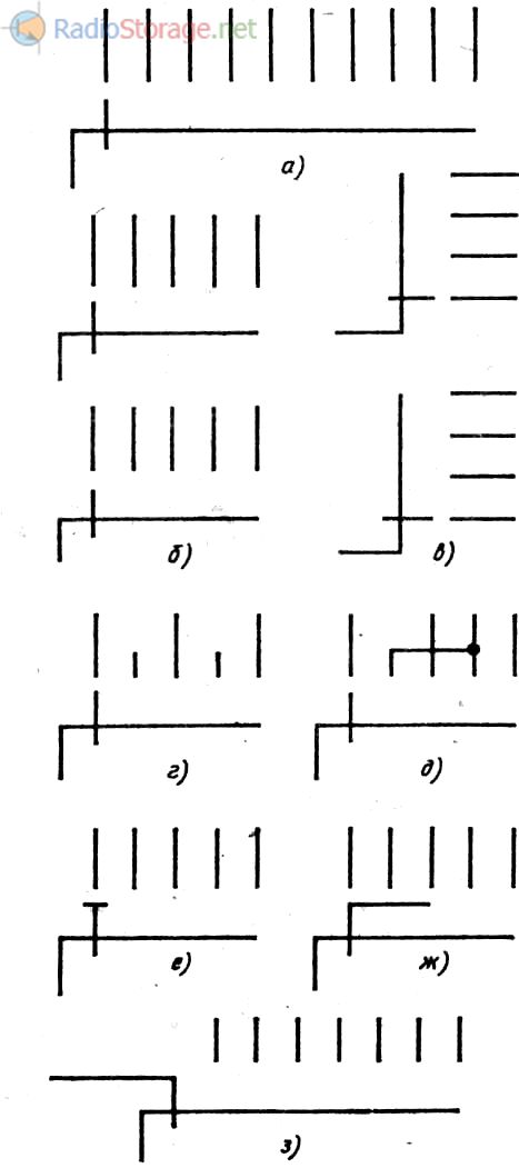
Switching devices is a large group of electrical and radio equipment elements designed to turn on, turn off and switch various electrical circuits (switches, switches, relays, etc.). Any of these elements contains one or more groups of contacts and a mechanism by which they can be closed or opened.
Conditional graphic symbols overwhelming majority switches, switches and relays are built on the basis of the basic symbols of make, break and changeover contacts and their variations.
Rice. 1. Switch and symbol on the diagrams.
Switches
Switches used to connect and disconnect electrical circuits. These products have two operating positions: “on” and “off”. The connection and disconnection of the circuit (closing and opening) is carried out by a movable contact, which is either permanently connected to one of the fixed contacts, and connected to the other when the switch handle is set to the “on” position, or is made in the form of a jumper connecting the fixed contacts in the same position .
However, regardless of the design of the switching unit, the closing contact is depicted in the diagrams in the same way - in the form of an inclined line in a line break electrical communication(Fig. 1 left).
Unlike the make contact, which is always shown in the open position, the break contact is shown in the closed position. GOST 2.755-74 establishes three equal symbols for such a contact (Fig. 1 on the right), however, within the same circuit it is recommended to use one of them. N
The standard does not establish the direction of movement of the moving contact (both breaking and closing) from the initial position to the final position (except for the cases that will be discussed below).
Designed for simultaneous switching of several electrical circuits, they may contain several make or break contacts or combinations thereof.
With a combined image of such a switch (i.e., in one place in the diagram), the lines indicating the moving contacts are drawn parallel to one another and connected by a mechanical connection symbol - two solid lines. The symbols of two such switches are shown in Fig. 2. The first of them (Fig. 2,a) contains two normally open contacts.

Rice. 2. Complex switches.
They can turn on (close) two electrical circuits, for example both wires mains power device or one wire in the power circuits of two devices at once. Using the second switch (Fig. 2.6), you can, for example, turn on the power measuring instrument and at the same time open the sensitive dial current meter.
If for some reason the contact groups of a complex switch have to be depicted in different parts diagrams, each of the moving contact symbols is provided with a segment of a dashed line of mechanical connection, and belonging to one product is indicated in the positional designation (Fig. 2, c, contact groups SA1.1, SA1.2 and SA1.3 belong to switch SA1).
When we spoke about the symbols of the normally open and closed contacts, we meant that their moving parts can be fixed in both the closed and open positions. However, there are switches whose contacts are not fixed in one of these positions, i.e., after removing the force acting on them, they return to their original state.
Such contacts are depicted differently in diagrams. If they want to show that the contact is not fixed in the closed position, at the end of the electrical communication line, symbolizing the fixed contact, a small triangle is depicted, the apex of which, as it were, pushes away the symbol of the moving contact (Fig. 3, a). The same is done with the symbol of the breaking contact. , not fixed in the open position (Fig. 3.6).

Rice. 3 and Fig. 4. Double switches.
Among the switches there are also those in which one moving contact can simultaneously close or open two electrical circuits. The symbols of such a contact clearly convey this idea (Fig. 4, c - contact with double closure, Fig. 4, b - with double opening).
The ESKD standard also provides for the designation of such features of switches as non-simultaneous operation of contacts in a group, the presence of locking in the closed or open position of the contacts of switches controlled by buttons (meaning that in the usual version such switching products do not have locking), sensitivity to impact external factors etc.
A distinctive feature of contact, triggered earlier than others, is a short line at the end of the moving contact symbol, directed in the direction of its movement when triggered. The designation of the early-acting closing contact is shown in Fig. 4,a, opening - in Fig. 4, b. If it is necessary to indicate that the contact, on the contrary, is triggered later than others in the group, the dash is directed in the opposite direction (Fig. 4, c, d).

Rice. 5. Designation of an early-acting closing contact.
Contact symbols without self-reset after tripping used in notation push-button switches, therefore, in addition to the sign of no self-return (a small circle on the symbol of a fixed contact), they also introduce a symbol of a manual drive - buttons.

Rice. 6. Designation of push-button switches.
For example in Fig. 6a shows the symbol of a push-button switch with return to initial position by pulling the button, in fig. 6.6 - with return by pressing the button again, and in fig. 6,a - with return via a separate drive, for example by pressing a special “Reset” button.
A sign of contacts, automatically returning to its original position when the circuit is overloaded or exceeding the permissible limits of changes in external factors (for example, temperature), is small rectangle sign on the moving contact symbol.
The physical quantity under the influence of which the contact returns to its original position is denoted by the generally accepted alphabetic symbol and the mathematical sign “>” (greater than) or “<» (меньше).
So, if the inscription “>” is placed next to the contact designation (see Fig. 7,a), this means that it reacts to voltage exceeding permissible level, and this one alphabetic symbol with the sign "<» указывает на чувствительность контакта к уменьшению напряжения ниже установленного значения (рис. 7,6). Аналогично обозначают и свойство контакта срабатывать при превышении максимально допустимой температуры (рис. 7,в).

Rice. 7. Designation of contacts with reaction to the level.
The letter code of products of this group (as well as switches) in the position designation is determined by the switched circuit and the design of the switch (or rather, the control method).
If the switch is used in the control circuit, signaling, measurement, etc., it is designated by the Latin letter S, and if in the power circuit, by the letter Q. The control method is reflected in the second letter of the code: push-button switches and switches are designated by the letter B (SB ), automatic (see below) - with the letter F (SF), all others - with the letter A (SA).
Switches
Switches- These are devices that switch one or more circuits to several others. The conventional graphic designation of a switching contact essentially consists of a combination of the symbols for the make and break contacts (Fig. 8), while also implying that the moving contact is fixed in both extreme positions.

Rice. 8. Switch and its designation on the diagrams.
Latching switch moving contact symbol not only in the extreme, but also in the middle (neutral) position, they are depicted between the designations of fixed contacts (at the same distance from them) and highlighted with a bold dot (Fig. 9, a).
If necessary to show contact with fixation in neutral and one of the extreme positions or without fixation in extreme positions, one or both symbols of fixed contacts are provided with triangles (Fig. 9,b).

Rice. 9. Latching switches, designation on diagrams.
In some cases they use transfer switches. When such a switch is moved from one position to another, the moving contact does not break the circuit corresponding to the previous position until it connects a new circuit. A contact with continuous switching is depicted with a short dash at the end (Fig. 9, c).
Other features of switching contacts (early or delayed operation, lack of self-reset, etc.) are indicated by the same signs as for normally open and closed contacts. Multi-pin switch symbols are built on the basis of corresponding switching contacts, connecting them with mechanical communication lines (Fig. 10).

Rice. 10. Multi-contact switch and its designation on the diagrams.
Complex switches characterized by the number of positions and directions (the latter is understood as the number of independent switched circuits, usually equal to the number of moving contacts).
The design of such switches can be very different. For example, biscuit switches, widely used in radio devices, consist of one or more biscuits and a locking mechanism.
Each biscuit, in turn, consists of two parts: a fixed one (stator), fixed to the base of the locking mechanism, and a movable one (rotor).
On the stator there are 12 springy fixed contacts, some of which (from one to four) are longer than the others, and on the rotor - depending on the number of positions - from one to four contacts in the shape of a ring or sectors with protrusions.
The elongated stator contacts are constantly connected to the movable contacts of the rotor, the rest are connected to them when the rotor is moved from one position to another. Depending on the number of biscuits and movable contacts, the switch may have a different number of positions and directions.
In the diagrams, switches of this type are shown as shown in Fig. 11, a. Here, the symbol in the form of a long line with a break at the left end denotes the output of the moving contact, the short line crossing it out is the moving contact itself, and the ends of the electrical communication lines located opposite it are fixed contacts, the number of which is equal to the number of switch positions.
Rice. 11. Roll switches with different numbers of positions and voltages.
If the switch has several directions, the number of such contact groups is increased accordingly, depicting them one under the other (Fig. 11.6) or next to each other (Fig. 11.c).
When the symbols of contact groups are located in different parts of the circuit, their belonging to the same switching device, as in previously considered cases, is indicated by the corresponding numbering in the positional designations (for example, SAl.l, SA1.2, etc.).
In positions in which the movable contact should not be connected to any circuit, the symbol of the corresponding fixed contact is shortened (Fig. 11d). The same is done if several fixed contacts are connected together (Fig. 86, (3). A moving contact with continuous switching of circuits is highlighted with a short dash (Fig. 11, e).
There are switches in which a moving contact is connected to several fixed contacts at once. This switching feature is shown by a line at the end of the moving contact symbol, “encompassing” the corresponding number of fixed contact symbols.
For example in Fig. 11g shows a switch in which three adjacent circuits are simultaneously closed in each position. If such a switch in each subsequent position connects a parallel circuit to circuits closed in the previous position, the moving contact symbol is modified, as shown in Fig. 11, h.
Among bib switches There are those in which the movable contacts are thin rollers connecting the ends of pairs of fixed contacts, each in its own group ( independent circuit switches).
This design feature is clearly reflected by the symbol of such a switch, where the symbol of a moving contact - a short dash - is depicted between the symbols of fixed contacts (Fig. 12).

Rice. 12. Switch of independent circuits.
In practice, you can find switches (for example, cam switches), the same contacts of which are repeatedly closed and opened depending on the position of the control knob.
It is very difficult to depict such a switching node using the basic symbols of make, break and switch contacts, therefore in such cases GOST 2.755-74 recommends other ways of constructing switch designations.
Two of them are illustrated in Fig. 13 and 14.

Rice. 13. Five-position switch.

Rice. 14. Five-position switch with a different principle.
The first of them shows five position switch(they are designated by numbers 1-5; letters a-e are introduced only to clarify the description of its work). In this switch, the connection of circuits a-e with each other is shown by segments of lines perpendicular to them with thick dots at the ends (electrical connection symbols).
In position 1 (connector lines opposite circuits o, b and d, e) the switch connects circuits a and b, d and d, in position 2 - circuits b and d, in position 3 - ive, guide, in position 4t-s « d, in position 5 - a and b, c and d.
The switch has a different operating principle, the designation of which is shown in Fig. 14. It also has five positions, but connects circuits a-a, b-b, etc. (essentially, it is a switch based on normally open contacts, which, with simpler switching, could be depicted as open circuits).
In its first position, circuits a-a and b-b are closed (this is indicated by the bold dots depicted below them, symbolizing the electrical connection), in the second - circuits c-c and b-b, in the third - a-a and d-d , in the fourth - b-b, in the fifth - all four chains.
Literature: V.V. Frolov, Language of radio circuits, Moscow, 1998.
To control lighting devices on a staircase or in a long corridor, the usual circuit with one “on/off” device is not suitable. To turn off the light in such a situation, you will have to go back to the only switch in the room. Not too convenient, don't you agree?
By installing a pass-through switch that allows you to control light bulbs from two places, you will significantly increase the level of comfort in your home or office. We will tell you how to choose the right device and how to install it correctly. Our article discusses popular connection options.
Before you go to a lighting store to buy the necessary materials, you first need to understand the terminology and various electrical switching devices.
For most novice electricians, a switch and a switch are the same thing. However, they are only superficially similar to each other. According to the principle of operation, these devices differ radically.
Both household switches and light switches look the same and have uniform housings, but are designed for fundamentally different connection schemes
A regular “SWITCH” is the simplest key that opens/closes an electrical circuit. It has one incoming and one outgoing wire. Plus, there are two- and three-key devices with a large number of contacts. However, these are simply two or three switches assembled together in a single housing.
A “SWITCH” is a switching device in which one incoming electrical circuit is switched to one of several output circuits. Often, such a device is also called a “changeover switch”, since it has a key for switching contacts from one position to another.
At a minimum, such a single-key device has three contacts (one incoming and a pair of outgoing). If there are two keys, then there are already six terminals (a pair at the input and four at the output).
The term “PASS-THROUGH SWITCH” refers to several switches connected to each other according to a specific circuit. Such a switch is designed to turn on/off a single light source from several points in a room or fenced area with lighting at once.

It is impossible to make a “pass-through” device from classic switches in order to save on purchases; for this it is necessary to use exclusively switches
As a result, a two-pin switch is designed to break one electrical circuit with the phase through which the light bulb is powered. And a three-pin switch is used to create new separate power circuits.
The first option is needed to stop the flow of current through any circuit, and the second option is needed to switch between circuits. Externally, both devices look exactly the same. This is a housing with one or more keys. In this case, the switch can be used in switch mode, but vice versa cannot.
It is impossible to turn a two-pin device into a three-pin one. But eliminating the use of one of the circuits is quite acceptable. But to organize light control from several points, you need to buy only switching devices with three or more contacts.
Types of household switching devices
Switches come in push-button, key and rotary types. The first option is usually used only as a bell at the front door. It is not suitable for lighting control.
But the second type for turning on/off lights in a residential building is just what you need. The rotating version is more intended for production and utility rooms. Such products do not have a very presentable appearance.
Depending on the number of keys, switches are:
- single-key;
- two-key;
- three-key.
They are divided into ordinary (pass-through), combined and (intermediate). The first ones have three contacts. For the latter, this three terminals is increased by multiplying by the number of keys. And the third has two entrances and exits. The latter are intended for circuits with not two, but several light switching points.

By type of control in private homes, light switches are usually standard keypads, but there are also models with sensors and remote control
According to the wiring diagram, switches are available for open () and hidden (built-in analogues) wiring. The first ones are attached to the wall with self-tapping dowels, and the second ones are fixed in the socket boxes with the help of expanding legs.
When choosing switches for connection according to the pass-through switch circuit, it is necessary to correctly select the number of keys (one for each connected group). If you plan to make two control points, then you will only need a pair of ordinary three-pin devices.
If more of these points are needed, then for each such place you will have to additionally take an intermediate crossover device to be included in a single system.
In the vast majority of cases, the key of a household switch has two positions for closing one of the circuits. But there are also modifications with a zero middle state. In this situation, both circuits are broken.
Marking on the switch body
The part of the switch where the contacts are located usually has special markings indicating the characteristics of the switching product. At a minimum, these are the rated voltage and current, as well as the designations of the wire terminals.

If the switch is selected for circuits with fluorescent lamps, then its marking must contain the letters “X” or “AX” (on ordinary ones there is only “A”)
When the light in fluorescent lamps is turned on, a sharp surge in inrush current occurs in the circuit. If LED or incandescent light bulbs are used, then this jump is not so large.
Otherwise, the switch must be designed for such high loads, otherwise there is a risk of burning the contacts in its terminals. This is why it is so important to choose special switches for fluorescent electric lamps.
For installation in a bedroom or hallway, a switch with IP03 is quite suitable. For bathrooms, it is better to raise the second digit to 4 or 5. And if the switching product is installed outdoors, then the degree of protection should be at least IP55.
Contact clamps for electrical wires on the switch can be:
- screw with and without a pressure plate;
- screwless spring.
The former are more reliable, while the latter greatly simplify electrical installations. Moreover, the best option is screw clamps with an addition in the form of a pressure plate. When tightened, they do not destroy the wire core with the tip of the screw.

According to GOST requirements, if the conductor has a cross-section of up to 1.5 mm, then it is unacceptable to use a screw clamp in which the end of the screw is rotated along the core to connect it to the switch
Also in the switch markings there are terminal designations:
- “N” – for the neutral working conductor.
- “L” – for conductor with phase.
- “EARTH” – for the neutral protective conductor to be grounded.
Plus, usually using “I” and “O” the position of the key in the “ON” and “OFF” modes is indicated. Manufacturer logos and product names may also be present on the case.
Lighting control from several places
There are several schemes for installing switches to turn on light from different ends of the corridor. The simplest of them involves the presence of switch keys in two places in the room remote from each other and one power line for the lamps.
If it is necessary to make more than two lighting switching points, then wiring the electrical wires will be somewhat more complicated. But there is nothing particularly wise here either.

If you follow the presented diagrams for connecting switches, then there will be no special problems with organizing control of the lamp from several points - you just need to avoid mixing up the wires
If, using a pass-through switch, you plan to supply voltage to a chandelier with two or three separate sets of light bulbs, then the circuit will become somewhat more complicated. Here you will have to mount switches with several keys, and there are much more terminals for wires.
Scheme #1: to turn on the light from two points
The easiest way is to organize control of the lighting fixture from two different places in the room. To do this, you only need a couple of standard switches and a few meters of electrical wiring.
Plus, you will need to follow the simplest rules of electrical installation to prevent electric shock and ensure the safe operation of the entire system in the future.

The “pass-through corridor switch” circuit with two switches is the most popular, it is widely used in corridors and bedrooms, as well as on stairs and verandas
When implemented, the outputs of both switches are connected by a pair of wires to obtain two separate supply circuits. Then a wire with a phase is connected to the input of one switching product, and a lead to the light bulb is connected to the input of the second.
As a result, in any position of both keys, the common power circuit of the “pass-through switch” will be either broken or connected. The light can be turned on and off from two different points.
This solution allows you to supply voltage to the lighting device when only one key is turned on. The second, on the other side of the room, always commutes one of the existing lines.
Scheme #2: for two lamps
The first scheme is the simplest and cheapest to implement. It is used most often. However, if there are several lamps in the room or the light bulbs in the chandelier are divided into two groups, then a similar version of a pass-through switch will not work.

If you need to supply power to two separate lines of lighting lamps, you will have to resort to installing two-key switches with six contacts each
In terms of installation technology and the devices used, this scheme practically repeats the first basic option. Only in this case you will have to lay more wires.
And in order to save at least a little on them, it is recommended to make the supply wire to the first switch in the circuit with a jumper. Pulling a couple of separate wires from the distribution box will be too expensive.
If there are three lines with lamps, then they are replaced with three-key analogues. In all other respects, the wiring diagram remains the same, only their number increases.
Scheme #3: for several switches
With two light switching points and one or more lighting groups, everything is quite simple. It needs some wiring and a couple of switches. But if you need to organize control from several places, you will have to purchase another type of switching device.

If you need to install several switches for one lamp, then you cannot do without a cross switch. In this device one of the circuits is transit
In such extreme switches, ordinary pass-through switches are placed, as in the first case. And between them a crossover analogue with four terminals for connecting the electrical wiring is then mounted.
When you press a key in such a switching device, the connected contacts are opened and immediately cross-connected into a new supply circuit. In addition to single-key cross switches, there are devices with a large number of keys. They are designed for circuits with several groups of light bulbs.
However, in this case, much more cores will have to be connected to the terminals. And here it is extremely important not to confuse anything. It is necessary to pay special attention to the correct electrical installation during such wiring.

If another “on/off” point is needed, then another crossbar is installed with serial connection of wires to the existing ones
Electricians recommend connecting switches to each other through a junction box. However, it is much easier to do this directly using a two-wire wire. Practice shows that such a connection is more expedient and does not violate electrical engineering standards. And the consumption of electrical wires is seriously reduced.
Practice-tested cross-switch connection diagrams are given in, the contents of which we advise you to familiarize yourself with.
Conclusions and useful video on the topic
There are few nuances of connecting switches so that lighting can be controlled from several points. But they exist. And you cannot miss them out of ignorance of their type when performing installation. To make it easier for you to understand all the intricacies of the schemes described above, we recommend that you watch the video materials below.
All about walk-through switches - principles of operation and installation:
How to connect a two key switch:
Connection diagram for pass-through (changeover) switches through a distribution box:
The use of pass-through switches greatly simplifies lighting control in a large room, making this process more convenient. It is not difficult to independently install such a system of several switches and wires. You just need to choose the right set of necessary switching devices.
How did you choose a pass-through switch for installation in a country house, office or apartment? What was the decisive argument for you in choosing a device? Please write comments in the block below, post photographs related to the topic of the article, share useful information and ask questions.