Do-it-yourself autogyro drawings of gyrobee. The gyroplane is a well-forgotten old one. Autogyros - the process of operating a flying vehicle
Read also
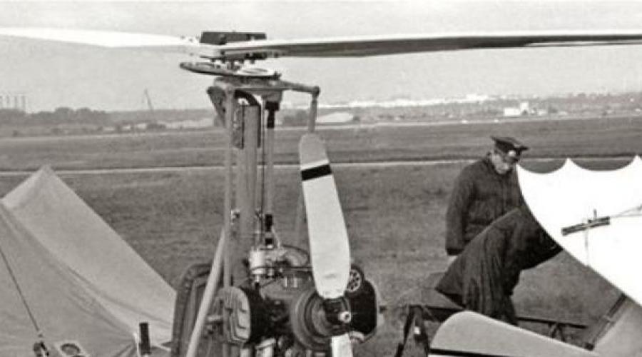
Light autogyro DAS-2M.
Developer: V. Danilov, M. Anisimov, V. Smerchko
Country: USSR
First flight: 1987
For the first time, the DAS autogyro flew into the air in a non-motorized version, towed by a Zhiguli car. It happened at one of the agricultural airfields near Tula. But it took another year, during which the designers worked on the engine, before the most experienced test pilot LII V.M. Semenov, after just one run, lifted the DAS-2M into the air. This event was later noted at the competitions of the ALS with a special prize from the Mil Design Bureau. The device, according to the test pilot, has good flight characteristics and efficient control.
Design.
Fuselage - truss, tubular, collapsible design. The main element of the fuselage is a frame consisting of horizontal and vertical (pylon) pipes with a diameter of 75 x 1, made of steel 30KhGSA. They are attached to a towing device with a lock and an air pressure receiver, a dashboard, a pilot's seat equipped with a seat belt, a control device, a three-wheeled, with a nose steerable wheel, a power unit mounted on a motor mount with a pusher propeller, a stabilizer, a keel with a rudder, a ball main rotor pivot. An auxiliary tail wheel with a diameter of 75 mm is installed under the keel. The pylon, together with struts with a diameter of 38 x 2 and a length of 1260 mm, tubular beams of the main wheels with a diameter of 42 × 2 and a length of 770 mm, made of titanium alloy VT-2, and braces with a diameter of 25 x 1 and a length of 730 mm from steel 30KhGSA form a spatial power frame, in the center of which is the pilot. The pylon is connected to the horizontal fuselage tube and the ball joint of the main rotor by means of titanium scarves. Bougie made of V95T1 duralumin is installed in the tubes in the area of installation of scarves.
The power unit is with a pusher propeller. It consists of a two-cylinder boxer two-stroke engine with a working volume of 700 cm3 with a gearbox, a pusher propeller and an electric starter, a friction clutch of the main rotor pre-rotation system, a gas tank with a capacity of 8 liters and an electronic ignition system. The power unit is located behind the pylon, on the motor frame.
The engine is equipped with a duplicated electronic non-contact ignition system and a tuned exhaust system.
The pushing wooden screw is driven by a V-belt gearbox, consisting of a driving and driven pulleys and six belts. To reduce the unevenness of the torque, dampers are installed on the gearbox.
The main rotor with a diameter of 6.60 m is two-bladed. The blades, consisting of a fiberglass spar, foam filling and coated with fiberglass, are installed with one horizontal hinge on a sleeve located on the pylon. At the ends of the blades there are uncontrolled trimmers for adjusting the conicity of the main rotor. On the axis of the main rotor, the driven gear of the pre-rotation gearbox and the sensor of the main rotor tachometer are installed. The gearbox is driven by means of cardan-splined shafts, an angular gearbox mounted on a pylon, and a friction clutch located on the engine. The friction clutch consists of a driven rubber roller mounted on the axis of the cardan-splined shaft, and a leading duralumin drum located on the engine axis. The friction clutch is controlled by a lever mounted on the control handle.
Changes in roll and pitch are carried out by a handle that affects the position of the lower control fork connected by rods to the upper fork, which, in turn, leads to a change in the inclination of the plane of rotation of the main rotor.
The directional control is carried out by a rudder connected by cable wiring to the pedals, which also control the nose wheel. To compensate for the hinge moment, the rudder is equipped with a horn-type compensator. The rudder and keel of a symmetrical profile are made of 16 plywood ribs 3 mm thick, pine stringers 5 x 5 mm, covered with percale and covered with nitro-lacquer. The keel is mounted on a horizontal fuselage tube with anchor bolts and two cable braces.
The autogyro chassis is three-wheeled. The front steering wheel with dimensions of 300 x 80 mm is connected to the pedals by means of a gear reducer having a gear ratio of 1:0.6 and is equipped with a drum-type parking brake with a diameter of 115 mm.
The instrument panel is located on the towing device truss. The instrument panel has a speed indicator, a variometer, an altimeter connected to an air pressure receiver, tachometers for the main and pusher propellers. On the control handle there is an emergency engine stop switch and a friction clutch control handle. The control levers for the throttle valve of the carburetor and the device for forced disengagement of the gears of the gearbox of the pre-rotation system are installed on the pilot's seat on the left. On the right is the ignition switch. To the left of the dashboard is the parking brake lever. The drive of all mechanisms of the autogyro is carried out using cables with Bowden shells.
Rotor diameter, m: 6.60
Max. takeoff weight, kgf: 280
Weight of an empty autogyro, kgf: 180
Fuel weight, kgf: 7
Specific load, kgf/m2: 8.2
Power point,
-power, hp: 52
-Max. screw speed, rpm: 2500
- screw diameter, m: 1.46
Speed, km/h,
- takeoff: 40
-landing: 0
- cruising: 80
-maximum: 100
Rate of climb, m/s: 2.0.
Autogyro DAS-2M.

Who in childhood did not dream of becoming a pilot, a conqueror of the fifth ocean of air! Many romantic natures do not give up this dream of theirs even at a more mature age. And they can realize it: at present, there is a wide variety of aircraft that even amateur pilots can fly. But, unfortunately, if such devices are factory-made and offered for sale, then their cost is so high that they are practically inaccessible to most.
However, there is another way - independent production of a reliable and relatively simple aircraft. For example, an autogyro. This article proposes a description of just such a design, which is within the power of almost any person involved in technical creativity. For the construction of a gyroplane, expensive materials and special conditions are not required - there is enough space directly in the apartment, if only the household and neighbors do not mind. And only a limited number of structural parts need to be turned.
For an enthusiast who decides to independently manufacture the proposed aircraft, I would recommend at first to assemble an autogyro-glider. It is lifted into the air by a tow rope attached to a moving vehicle. The flight altitude depends on the length of the cable and can exceed 50 meters. After climbing to such a height and dropping the cable by the pilot, the gyroplane is able to continue flying, smoothly descending at an angle of about 15 degrees to the horizon. Such planning will allow the pilot to develop the control skills he needs in free flight. And he will be able to start them if he installs an engine with a pusher propeller on a gyroplane. In this case, no changes in the design of the aircraft will be required. With the engine, the gyroplane will be able to reach speeds of up to 150 km/h and rise to a height of several thousand meters. But about the power plant and its placement on the aircraft later, in a separate publication.
So, a gyroplane. Its basis is three duralumin power elements: keel and axial beams and a mast. In front on the keel beam there is a steerable nose wheel (from a sports microcar-kart) equipped with a brake device, and at the ends of the axle beam there are side wheels (from a scooter). By the way, instead of wheels, you can install two floats if you plan to fly in tow behind a boat.
In the same place, at the front end of the keel beam, a truss is installed - a triangular structure riveted from duralumin corners and reinforced with rectangular sheet overlays. It is designed to attach a tow hook, which is designed so that the pilot, by pulling the cord, can unhook from the tow line at any time. Aeronautical instruments are also fixed on the farm - the simplest home-made indicators of airspeed and lateral drift, and under the farm - a pedal assembly with cable wiring to the rudder. At the opposite end of this beam, plumage is installed: horizontal (stabilizer) and vertical (keel with rudder), as well as a safety tail wheel. All pictures will enlarge when clicked.

Autogyro layout:
1 - farm; 2 - towing hook; 3 - clip fastening the towing hook (D16T); 4 - airspeed indicator; 5 - indicator of lateral drift; 6 - stretching (steel cable 02); 7 - control knob; 8 - rotor blade; 9 - rotor head of the main rotor; 10 - rotor head bracket (D16T, sheet s4, 2 pcs.); 11 - mast (D16T, pipe 50x50x3); 12 - seat back mounting bracket (aluminum, sheet s3, 2 pcs.); 13 - seat back; 14 - "aircraft" version of the control stick; 15 - seat frame; 16 - bracket for "airplane" control stick; 17 - seat mounting bracket; 18.25 - rollers of the control cable wiring (4 pcs.); 19 - brace (D16T, corner 30x30, 2 pcs.); 20 - mast mounting bracket (D16T, sheet s4.2 pcs.); 21 - upper brace (steel, angle 30x30, 2 pcs.); 22 - horizontal tail; 23 - vertical plumage; 24 - tail wheel; 26 - left branch of the control wiring (cable 02); 27 - axial beam (D16T, pipe 50x50x3); 28 - mount of the axle of the side wheel; 29 - lower brace (steel, angle 30x30.2 pieces); 30 - seat support (D16T, corner 25x25, 2 pcs.); 31 - braking device; 32 - pedal assembly; 33 - keel beam (D16T, pipe 50x50x3)
In the middle of the keel beam there is a mast and a pilot's workplace - a seat with car seat belts. The mast is attached to the beam with two duralumin plate brackets at a slight angle to the vertical back and serves as the basis for the rotor of a two-bladed main propeller. The rotor mechanism is also connected to the mast by similar plate brackets. The screw rotates freely and is untwisted due to the oncoming air flow. The axis of the rotor can be tilted in any direction with the help of a handle, conventionally called "hang-on", with which the pilot regulates the position of the gyroplane in space. Such a control system is the simplest, but differs from the standard one used on the vast majority of aircraft in that when the handle moves away from itself, the gyroplane does not decrease, but, on the contrary, gains altitude.
If desired, it is also possible to install an “airplane” control knob (in the figure it is shown by a dash-dotted line). In this case, the design naturally becomes more complicated. However, it is necessary to choose the type of control even before the construction of the gyroplane. Alteration is unacceptable, since the piloting skills acquired with the "delta" handle, when switching to the "airplane" can give an undesirable result.
In addition, when moving on the ground, the pilot controls the nose wheel with his feet, and after takeoff, when the empennage becomes effective with increasing speed, he also controls the rudder with his feet. In the first case, he steers, alternately pressing with his right or left foot on the corresponding shoulder of the crossbar of the braking device, which is on the wheel; in the second - on one or another pedal connected by cable wiring to the rudder.
The braking device is used during the run when landing on the runway. It is also not particularly difficult. The pilot with his heels presses the friction clutch (or simply a wooden board) to the tire of the wheel, forcing them to rub against each other and thereby dampens the speed of the aircraft. The most simple and cheap!
Insignificant mass and dimensions of the autogyro make it possible to transport it even on the roof of a car. The propeller blades are detached. They are installed in their workplace immediately before the flight.
FRAME MANUFACTURING
As already mentioned, the basis of the autogyro frame is the keel and axle beams, the mast. They are made of duralumin square tube 50x50 mm with a wall thickness of 3 mm. Similar profiles are used in the construction of windows, doors, shop windows and other building elements. It is possible to use box-shaped beams from duralumin corners connected by argon-arc welding. The best material option is D16T.
All holes in the beams were marked so that the drill only touched the inner walls without damaging them. The drill diameter was chosen so that the MB bolts fit into the holes as tightly as possible. The work was carried out exclusively with an electric drill - the use of a manual drill for these purposes is undesirable.

Most of the holes in the frame parts are coordinated in the drawings. However, many of them were drilled in place, as, for example, in the plate brackets connecting the keel beam to the mast. First, the right bracket, screwed to the keel beam, was drilled through the holes in the base of the mast pressed against it, then the left bracket was screwed on and also drilled, but through the finished holes of the right bracket and mast.
By the way, in the layout drawing it is noticeable that the mast is slightly tilted back (for this, the base is beveled before installation). This is done so that the main rotor blades have an initial angle of attack of 9 ° on the ground. Then, even at a relatively low towing speed, a lifting force appears on them, the screw begins to rotate, lifting the gyroplane into the air.
The axle beam is located across the keel beam and is attached to it with four MB bolts with locking split nuts. In addition, the beams are connected by four steel angle braces for greater rigidity. Wheel axles are attached to the ends of the axle beam with paired clips (suitable from a scooter or motorcycle). The wheels, as already mentioned, are scooter, with bearings closed to prevent dust and dirt from entering them with caps from aerosol cans.
The frame and back of the seat are made of duralumin pipes (parts from baby cots or strollers are very suitable for this). At the front, the frame is attached to the keel beam with two duralumin corners 25x25 mm, and at the rear - to the mast with a bracket made of steel corner "ka 30x30 mm. The back, in turn, is screwed to the seat frame and also to the mast.
Rings cut from the rubber chamber of a truck wheel are put on the seat frame. On top of them, a foam cushion sheathed with a durable fabric is laid and tied with ribbons. A cover made of the same fabric is pulled over the back.
The front landing gear is a sheet steel fork with a kart wheel that rotates around a vertical axis. The axis is a short M12 bolt inserted into the hole of the sole (rectangle made of steel sheet), which is attached to the keel beam from below with four Mb bolts. An additional round hole is cut out under the head of the axle bolt in the keel beam.
From the sides, to the feathers of the fork of the nose wheel, a braking device is pivotally suspended. It is assembled from a tubular cross member, two corner stringers and a wooden clutch. Let me remind you that the protruding ends of the crossbar allow the pilot to turn the steering wheel with their feet.
In the initial position, the device is held by two cylindrical tension springs hooked to the brackets on the nose of the keel beam, and a cable passed through the holes in the friction board. The springs are adjusted so that in the absence of control actions of the pilot, the wheel is in the plane of symmetry of the autogyro.

The pedal control of the aerodynamic steering wheel in the air is also quite simple. Both pedals, together with the parts riveted to it, are connected by hinge bolts to a pipe, which is screwed to a corner on the keel beam. From above, sections of cable are attached to the pedals, stretching to the rudder horns on the keel. The control wiring has four guide rollers, the design of which prevents the cables from falling out of them. The tension of the cables is supported by coil springs attached to the pedals and a plate bracket on the keel beam. The springs are adjusted so that the rudder is in the neutral position.

The design of the farm is described in some detail above. Therefore, I will focus on what is attached to the farm - on home-made aeronautical instruments, or rather, on one of them - an airspeed indicator. This is a glass tube open on top, in which a light plastic ball is placed. At the bottom, it has a calibrated hole directed towards the flight of the gyroplane. The oncoming airflow causes the ball to rise in the tube, and its position determines the airspeed. You can calibrate the indicator by placing it in the window of a moving car. It is important to accurately plot the speed values between 0 and 60 km/h, as these are the values that are important during takeoff and landing.
The horizontal plumage is made of sheet duralumin 3 mm thick. The plumage has two slots for duralumin mast support angle struts. At the points of bolted attachment of the empennage with the keel beam, pads are riveted to the stabilizer to increase the rigidity of the connection.

Vertical plumage is more difficult. It consists of a keel and rudder cut from plywood, the first one is 10mm, the second is 6mm. The individual edges of these parts are edged with a thin steel tape. The keel and rudder are connected to each other by three card loops (on the port side).

Two counterweights weighing 350 g each are attached to the aerodynamic rudder horn with a through bolt Mb (they are needed to eliminate the flutter phenomenon).
The trim tab on the trailing edge of the handlebar is made from soft sheet aluminium. By bending this plate to the right or left, you can adjust the accuracy of the steering wheel.
On both sides of the steering wheel screwed horns, curved from a steel sheet. Attached to them are the heading control cables.
The vertical tail is attached to the keel beam on the right and for greater rigidity it is reinforced with two brackets made of 25x25 mm duralumin corner.

At the end of the keel beam, a tail wheel is installed (from roller skates). It protects the vertical tail from damage in case of accidental capsizing of the gyroplane on the tail, as well as during takeoff or landing with the nose too high.
RECOMMENDATION:
preliminary check of the gyroplane on the ground
You have assembled a gyroplane. Before proceeding with the manufacture of the rotor, check how the ready-made mechanisms work. It is best to do this on the site from where the gyroplane flights are supposed to take place.
Sit on the seat and make sure you are comfortable and have your feet on the pedals. If necessary, place an extra pillow under your back. Jump on the seat - the pillow should not allow the body to touch the frame.
Kick the nosewheel back with your feet and watch the springs return it to neutral. Make sure that in this position the springs are neither overtight nor loose. There must be no play in all connections.
Attach the gyroplane with a cable no longer than ten meters to the vehicle and taxi at a speed of no more than 20 km/h. Warn the driver not to suddenly brake or slow down suddenly.
Take your feet off the brake bar and see if the gyroplane can handle a straight line. Otherwise, adjust the tension of the springs. Learn to automatically find the hook release cord and release the towline with your hand.
The main rotor, located at the top of the mast, is the most complex assembly in the design of a gyroplane. From the quality of workmanship, accuracy of assembly and the accuracy of its operation depends, without exaggeration, the life of the pilot. The main materials of the parts of this unit are D16T duralumin and ZOHGSA steel (all duralumin parts are anodized, steel parts are cadmium).
The rotor housing is perhaps the most important part, since in flight it is on the lugs of the housing that the entire structure of the gyroplane hangs. Two bearings are located in the housing itself - radial and angular contact, richly lubricated with grease. The housing with bearings rotates on the rotor axis. At the top of the axle there is a split slotted nut M20x1.5 (it should be noted that there are no simple nuts in the design of the gyroplane: the most important of them are cottered, the rest are self-locking). A blind cover that hides the axle nut protects the bearings from dust and moisture.
At the bottom, the rotor axis is fixedly connected to the autogyro control stick. By moving the handle, it is possible to change the position of the rotor in space, since the hinged connection of the axle with the trunnion and the trunnion with its body allows the axis to deviate within the limits dictated by the diameter of the limiter hole.
The rotor is bolted to the top of the mast using two plate brackets.
RECOMMENDATION:
gyroplane alignment check
When the rotor head is ready and installed on the gyroplane, it is necessary to check the alignment of the gyroplane. Insert a bolt into the ears of the rotor housing, which will fasten the rotor head with rotor blades, and hang the autogyro for this bolt, for example, on a strong tree branch.

Sit on the seat and grab the control handle. Keep her neutral. Have an assistant determine the position of the autogyro mast. It should be tilted forward at an angle between 2-6° (ideally 4°). This check, commonly referred to as weight balancing, must be repeated every time the weight of the pilot or gyroplane changes. In all cases, you cannot fly without such a check.
If the indicated angle is outside the permitted range, then either move the pilot or add a little ballast to the tail section. But if there has been a significant change in the mass of the pilot (it has exceeded 100 kg) or an engine is installed on the autogyro, then it is necessary to make new ones - thicker plate brackets that hold the rotor at the top of the mast.
The main rotor blades are completely identical, so it is enough to describe the manufacturing process of only one of them.
Along the entire working length of the blade, its cross-sections are the same, no twist or change in geometric parameters is provided. This greatly simplifies things.

The best material for the frontal part of the blade is delta wood, which was used in aviation and maritime affairs. In its absence, you can make an analogue yourself by gluing thin sheets of plywood with fiberglass gaskets with epoxy resin. Aircraft plywood 1 mm thick is suitable for such a substitute. Since plywood sheets of the length required for the manufacture of blades are not produced, it is possible to glue the plywood strips cut to the mustache. Joints in adjacent sheets should not be located one above the other, they must be spaced apart.
It is better to glue on a flat surface, placing a plastic film on which epoxy glue does not stick. It is necessary to dial a total thickness of 20 mm. After applying the glue, the entire "pie" of the future blade should be pressed down with some long and even object with a load and left to dry completely for a day. In terms of its mechanical properties, the resulting composition is no worse than real delta wood.
The specified profile of the leading edge (toe) of the spar is obtained using a template in the following way. Grooves are made along the entire span of the spar with a step of 150-200 mm in the leading edge until the template fits completely to the spar. The wood between the grooves is planed to fit the ruler.
In the rear edges of the spar with a planer (you can cycle), "quarters" 10 wide and 1 mm deep for plywood sheathing are selected. The lower skin sheet (flush with the spar) is glued with epoxy resin, and to it and the spar - PS-1 foam sheets, which are pre-planed to a height of 20 mm. The foam layer is given the necessary shape according to the pattern of the top of the blade profile. A pine lath is used as the trailing edge. The top skin was glued last: it was enough to press it with clamps to the “quarter” of the spar and the trailing edge - and the plywood sheet itself took the desired shape (the trailing edge of the blade should be slightly bent upwards, as shown in the figure).
Each blade has a weight of 100 g installed in the fairing on the leading edge, and a folding trimmer on the rear. Steel plates are riveted in the butt part of the blade, through which holes are drilled in the spar for attaching the blade to the rotor head.
RECOMMENDATION:
blade balancing and tuning
"After manufacturing and painting, the blades must be adjusted. Give this operation the most serious attention. Keep in mind that the cleaner and smoother the surfaces of the blades, the more lift they will create, and the gyroplane will be able to take off at a lower speed.
Attach the blades to the rotor head and check the balance. If any blade is heavier and its end drops lower, then drill out part of its lead weight, ensuring that the blades are even. If this operation does not work (no more than 50 g can be removed), then drill several shallow holes in the thickest section of the light blade profile and fill them with lead.
Since the tips of the blades during rotation have a peripheral speed of about 500 km / h, it is very important that they rotate in the same plane. Stick two colored plastic tapes on the leading edges at the very end of the blades. On a windy day, choose a spot where the wind blows constantly at about 20-30 km/h (check with the airspeed indicator) and steer the gyro into the wind. Tie it with a five-meter rope to a stump or stake firmly driven into the ground.
Sit on the seat, tie yourself with straps and back off together with the gyroplane so that the rope is taut. Holding the control stick with your left hand, place the rotor in a horizontal position, and spin the blades with your right hand as much as you can. Your assistant should observe the rotation of the ends of the rotor from the side.
Gradually tilt the rotor back and let it spin in the wind to a higher speed. If the multi-colored stripes rotate in the same plane, the blades have the same pitch. If you feel the glider shaking or the assistant shows that the blades are not rotating in the same plane, then immediately unload the rotor by moving it to a horizontal position or even tilting it forward. Bending the trimmers at a slight angle up or down, achieve the correct rotation of the blades.
As the rotor speed increases, the airframe will rock and the front wheel will rise. In this case, the rotor will be deflected back, which will lead to its even more intensive unwinding. Put your feet on the ground and control the position of the autogyro in space. If you feel that it is taking off, then immediately unload the rotor by pulling the control stick towards you. Having practiced this way, you will soon be ready for the first flight.
Do-it-yourself autogyro video
PILOT PRACTICE
Since not only the pilot is involved in the flight, but also the driver of the car, there must be full interaction between them. It is best if, in addition to the driver, there will be one more person in the car who will be able to monitor the flight and receive all the pilot's signals (decrease or increase in speed, etc.).
Before flying, check the technical condition of the gyroplane again. At first, use a relatively short tow rope no longer than 20 m. Be sure to warn the driver that you should accelerate smoothly and never brake sharply.
Position the autogyro against the wind. Spin the rotor with your right hand and wait until it begins to gain momentum due to air pressure. If the wind is light, then command the driver to move at a speed of 10-15 km / h on the airspeed indicator. Continue helping the rotor with your hand as long as you can.
Tilt the rotor all the way back as you accelerate and give the driver a signal to increase speed to 20-30 km/h. Steer the nose wheel behind the vehicle in a straight line. When that wheel is off the ground, put your feet on the pedals. By manipulating the control stick, maintain such a position of the autogyro that it moves only on the side wheels, neither nose nor tail touching the ground. Wait for the increased airspeed to lift the gyro into the air in this position. Adjust the flight altitude by longitudinal movements of the control stick (the rudder is not effective in this case, since the glider is towed on a cable). Avoid any slack in the towline while in flight. Do not corner at high speed.
Before landing, line up behind the vehicle until it has reached the end of the runway. Gently tilt the rotor forward and fly at a height of about a meter. Maintain this position with small "jerks" of the control knob. (In general, unlike the control of an aircraft, on a gyroplane, the movements of the handles should not be smooth, but sharp, literally jerky.)
Signal the driver to slow down. When he does, tilt the rotor all the way back. The rear wheel of the gyroplane must be the first to touch the ground. Keep the rotor tilted back to prevent slack in the towline. Having stopped, let the car turn around and move with it to the starting point. Keep the rotor in such a position that it continues to rotate. If there will be no more flights, then put the rotor horizontally and, when the speed drops, stop it by hand. Never leave your seat while the rotor is spinning, otherwise the gyroplane could take off without you.
Gradually, as you master the piloting technique, increase the length of the towing cable to one hundred meters and climb to a greater height.
The last stage of mastering the flight on a gyroplane will be free flight after uncoupling from the towline. Never reduce the airspeed below 30 km/h in this mode!
From a height of 60 m, the free flight range can reach 300 m. Learn to make turns, climb to great heights. If you start from a hill, then the flight range can be kilometers.
This time, friends and comrades, I propose to move to a different element of vehicles - air.
Despite the all-encompassing hell and death on earth, we do not lose hope and dream of conquering heaven. And a relatively inexpensive means for this will serve us as a miracle wheelchair with a propeller, whose name is autogyro.

Autogyro(autogyro) - a rotary-wing ultralight aircraft, in flight leaning on the bearing surface of a freely rotating main rotor in autorotation mode.
In another way, this thing is called as gyroplane(gyroplane), Gyrocopter(gyrocopter), and sometimes Rotoplan(rotaplane).
A bit of history
Autogyros were invented by Spanish engineer Juan de la Sierva in 1919. He, like many aircraft designers of that time, tried to create a flying helicopter and, as is usually the case, he created it, but not what he originally wanted. But he was not particularly upset by this fact and in 1923 he launched his personal apparatus, which flew due to the effect of autorotation. Then he washed down his own company and slowly riveted his gyrocopters until he died. And then a full-fledged helicopter was designed, interest in autogyros disappeared. Although they continued to be produced all this time, they were (and are) used for narrow purposes (meteorology, aerial photography, etc.).


Specifications
Weight: 200 to 800 kg
Speed: up to 180 km/h
Fuel consumption: ~15 l per 100 km
Flight range: from 300 to 800 km

Design


By design, the autogyro is closest to helicopters. In fact, he is a helicopter, only with an extremely simplified design.

The design itself includes the following key elements: the supporting structure - the "skeleton" of the apparatus, to which the engine is attached, 2 propellers, the pilot's seat, control and navigation devices, tail unit, landing gear and some other elements.
Direct control is carried out by two pedals and a control lever.

The simplest gyrocopters need a small run of 10-50 meters to take off. This distance decreases depending on the increase in the strength of the headwind and the degree of spinning of the main rotor by the time the takeoff starts.
A feature of the autogyro is that it flies as long as there is an air flow on the main rotor. This flow is provided by a small pusher screw. It is for this gyroplane that at least a small takeoff is needed.
However, more complex and expensive gyroplanes, equipped with a mechanism for changing the angle of attack of the blade, are capable of taking off vertically upwards from a standstill (the so-called bounce).
Changing the position of the autogyro in the horizontal plane is achieved by changing the angle of inclination of the entire plane of the main rotor.
An autogyro, like a helicopter, is capable of hovering in the air.

If an autogyro engine fails, this does not mean the certain death of the pilot. If the engine is turned off, the autogyro rotor goes into autorotation mode, i.e. continues to rotate from the oncoming air flow while the apparatus moves at a downward speed. As a result, the gyroplane descends slowly, rather than falling like a stone.

Varieties
Despite the simplicity of design, gyrocopters have some design variability.
Firstly, these aircraft can be equipped with both a pulling propeller and a pushing propeller. The former are typical for the historically very first models. Their second screw is located in front, like some aircraft.
The second - have a screw in the back of the device. Pusher gyroplanes are the vast majority, although both designs have their advantages.

Secondly, although the autogyro is a very light air vehicle, it can carry a couple more passengers. Naturally, there must be appropriate design possibilities for this. There are gyroplanes with the ability to transport up to 3 people, including the pilot.
![]()

Thirdly, a gyroplane may have a fully enclosed cockpit for the pilot and passengers, a partially enclosed cockpit, or may not have a cockpit at all, which is retracted for carrying capacity or better visibility.

Fourthly, it can be equipped with additional nishtyaks, such as a swashplate and so on.

Combat use
The effectiveness of the gyroplane as a striking weapon is, of course, low, but it managed to be in service with the SA for some time. In particular, at the beginning of the 20th century, when the whole world was engulfed in helicopter fever, the military watched the development in this industry. When full-fledged helicopters did not yet exist, there were attempts to use the gyrocopter for military purposes. The first gyrocopter in the USSR was developed in 1929 under the name KASKR-1. Then, over the next ten years, several more models of gyroplanes came out, incl. gyroplanes A-4 and A-7. The latter took part in the war with the Finns as a reconnaissance, night bomber and evacuator. Although there were certain advantages in using a gyroplane, all this time the military leadership doubted its necessity and the A-7 was never put into mass production. Then, in 1941, the war began and there was no time for that. After the war, all forces were thrown into the creation of a real helicopter, but the autogyro was forgotten.

The Soviet autogyro A-7 was armed with 7.62 PV-1 and DA-2 machine guns. It was also possible to mount FAB-100 bombs (4 pcs.) And RS-82 unguided rockets (6 pcs.)

The history of the use of gyroplanes in other countries is about the same - the devices were used at the beginning of the 20th century by the French, British, Japanese, but when helicopters appeared, almost all gyroplanes were decommissioned.
Subject and PA
It is probably clear why the gyroplane became the subject of "PA Techniques". Very simple, light, maneuverable - with a certain straightness of the hands, it can be assembled at home (apparently, tales about convicts and a helicopter from the Druzhba chainsaw appeared from here).

Despite all its advantages, we get a good opportunity to conquer the airspace in very bad environmental conditions.

In addition to the banal movement through the air and the transportation of a little bit of cargo, we get a good combat unit that can be tactfully used in reconnaissance and patrol operations. Moreover, it is quite possible to install automatic weapons, as well as the use of live ammunition for bombing. As they say, the need for invention is cunning, there would be a desire.

So, let's sum up. I divided the advantages of the subject into absolute and relative. Relative - in comparison with other aircraft, absolute - in comparison with vehicles in general, incl. and ground.
Absolute Benefits
Ease of manufacture and repair
Ease of operation
Ease of controls
compactness
Low fuel consumption
Relative advantages
High maneuverability
Strong wind resistance
Security
Landing without run
Low vibration in flight
disadvantages
Low load capacity
Low security
High sensitivity to frost
Sufficiently loud propeller noise
Specific disadvantages (rotor unloading, somersault, autorotation dead zone, etc.)
YouTube about subject