Automatic traffic light signaling. Crossing signaling devices At unmanned crossings, crossing traffic lights are supplemented with a white-lunar flashing light. The closing of the crossing is carried out by workers of the drafting or locomotive crew using
Read also
Places where railroads and roads intersect at the same level are called railroad crossings. Crossings serve to improve traffic safety and are equipped with fencing devices.
Depending on the intensity of train traffic at crossings, fencing devices are used in the form of automatic traffic light signaling, automatic crossing signaling with automatic barriers. Railway crossings can be equipped with automatic traffic light signaling devices; they can be guarded (serviced by an employee on duty) or unguarded (not serviced by an employee on duty). In this course project, the crossing is guarded, with automatic barriers with a beam length of 6 meters. Crossing traffic lights are used type II-69. An electric bell of the ZPT-24 type is placed on the mast of the crossing traffic light. These traffic lights use LED heads with a supply voltage of 11.5 V.
The control circuit for crossing signaling on a single-track section with numerical code automatic blocking includes the following relays: 1I. 2I pulse track relays are used to fix the vacancy-occupancy of a block area, I - general repeater of pulse track relays, DP - additional track relay, DI additional pulse, IP proximity detector (see sheet 9.1), IP1, 1IP, PIP proximity detector repeaters , N - direction relay, 1N, 2N - direction relay repeaters, B - switching relay, KT - control thermal relay, 1T, 2T - transmitter relays, 1PT, 2PT - direction relay repeaters, K - control relay, F, Z - signal relay, Zh1 - relay repeater Zh, 1S - counter relay, B - blocking relay, NIP - proximity detector in an unknown direction of movement, B1Zh, B1Z - blocking relays.
The state of the circuit corresponds to a given odd direction of movement, a free approach section, and an open crossing.
Within the block section on which the crossing is located, two track circuits 3P, 3Pa are equipped, in which, for a given odd direction of movement, the supply end is 1P, and the relay end is 2P, relay I is a pulse track type IVG - reed switch. When the block section is in a free state, the 3Pa rail circuit from traffic light 4 through contact 1T is encoded with a code, the meaning of which is determined by the signal reading of traffic light 1. At the crossing, relay 2 I operates in the incoming code mode, as well as its repeaters 1T, I. Through the contact of a common pulse repeater relay (relay I), the BS-DA decoder is turned on, the output circuits of which activate the signal relays, Ж, З, Ж1, depending on the readings of the traffic light ahead. Through the front contacts of relay Zh, Zh1, and the normal contact of relay N, relay 1PT (direction relay repeater) is activated. Relay 1T, operating in pulse mode, switches its contact in the relay circuit 1TI, which in turn transmits codes to the track circuit 3P.
When a train enters the Ch1U departure section, the crossing alarm is activated in two approach sections. From this moment on, the IP notification relay at traffic light 3 is de-energized. By releasing the armature, this relay changes the polarity of the current from forward to reverse in the IP relay circuit at the crossing. Excited by a current of reverse polarity, this relay switches the polarized armature, de-energizing the 1IP relay at the crossing. After de-energizing, relay 1IP turns off relay IP1. IP1 turns off relay B, the crossing is closed. When the train enters section 3P at traffic light 3, the pulse operation of relay 2I stops, the BS-DA decoder is turned off, relay Zh is de-energized, it turns off its repeater Zh1, and relay Zh1 in turn de-energizes repeaters Zh2, Zh3. At the crossing, the IP relay is de-energized by the contacts of the signal relay repeater Zh1, and the IP relay de-energizes the PIP relay. At the same time, at traffic light 3, through the rear contact of relay Z3, the OI relay is triggered, which, when triggered, prepares the coding circuit of the track circuit 3P, following the departing train. The transmission of the KZh code after the departing train occurs from the moment the traffic light 3 has completely passed. When the train enters section 3P, the counting circuit is activated at the crossing, and relays 1C, B1ZH, B1Z, B are energized.
The first to operate is the counter relay 1C, along the chain: front relay contacts NIP, 1N, K, Zh1, and rear relay contacts 1IP, PIP.
After relay 1C has triggered, it prepares the switching circuit for relays B1ZH, B1Z, they operate only after the train enters section 3Pa. When the train enters 3Pa, the operation of the pulse relays stops: 2I, the general repeater I, and the transmitter relay 1T, and the decoder also stops working. The decoder turns off relay Zh, Z, relay Z turns off 1PT and K, relay contact Z turns off the NIP relay. Since complete liberation section 3P at the crossing, from the KZh code pulses coming from traffic light 3, relays 1I, DI begin to operate. It is energized by the DP relay and closes the front contact in the power supply circuit of relay 1 IP. 1IP is energized. After the train completely vacates section 3P, the blocking relay circuit is activated. 1IP becomes energized and de-energizes the power circuit of relay 1C with its front contact.
Relay-counter 1C has a drop-off delay, due to this, a charging circuit for capacitors BK2 and BK3 is created, as well as an excitation circuit for relay B1Zh.
After this, relay B1Zh becomes energized. After the relay-counter 1C is de-energized, the charging circuit of capacitors BK2, BK3 is interrupted. The front contact of relay B1Z and through the rear contact Z1 closes the excitation circuit of relay B and the charge of capacitor BK1. Relay B opens the power circuit of relay B1Zh. After some slowdown, relay B1Zh will de-energize and turn off relay B. After capacitor BK1 discharges, relay B releases the armature and again closes the excitation circuit of relay B1Zh.
The operation of the blocking relays B1Z and B begins after the complete release of section 3Pa, from this moment the KZh code is supplied from traffic light 4 to the 3Pa rail circuit, at the crossing in the KZh code mode, relay 2I begins to operate, then the general repeater I is triggered, then the decoder is turned on, they stand up under current relay Zh, Zh1, relay 1PT. The charging circuit of the capacitance BK4, BK3 is closed, passing through the front Zh1, rear Z, and the front 1PT, DP, B1Zh, relays B1Z and B are activated.
B1Zh will be de-energized due to the discharge of capacitance BK3, BK2. The blocking relays continue to operate until the second removal section is completely freed.
In case of violation of the estimated time of passage of the train along the second section of the removal, the operation of relays B1ZH, B1Z, B stops, the contact of relay B turns off the NIP, the NIP relay turns off the relay IP1, the crossing remains closed, the crossing will open only when the train moves away from the traffic light two block sections.
Railway crossings are places where railways and roads (tram tracks, trolleybus lines) intersect at the same level and, depending on operating conditions, are equipped with one of following devices: automatic traffic light alarm; automatic traffic light signaling with automatic barriers; automatic warning alarm with non-automatic barriers.
With automatic traffic light signaling, a crossing on the side of the highway is fenced with two crossing traffic lights, each of which has two signal heads with red filters and an electric bell. When the crossing is open, no signals are given; when closed, light (two alternately flashing red lights) and sound (loud bell ZPT-12 or ZPT-24) signals are given.
At crossing traffic lights, you can also install a third head, which signals with a moon-white light that the crossing is open.
With automatic traffic light signaling with automatic barriers, the crossing from the side of the highway is additionally fenced with a barrier bar. When the crossing is open, the barrier beam is in vertical position, when closed - in a horizontal (blocking) position.
The barrier beam is painted with red and white stripes and is equipped with three electric lights with red glass, located at the end, in the middle, at the base of the beam and directed towards the road. The end light is double-sided and also has clear glass.
A lowered barrier beam signals three red lights towards the road and a white light towards the railway. In this case, the end light lights up with a continuous fire, the other two flash alternately.
When the crossing is closed, the barrier beam is lowered 4-10 seconds after the alarm starts working. When the beam is in a horizontal position, the lights on the crossing traffic light and beam continue to light, and the electric bell turns off.
Automatic barriers are also equipped with devices for not automatic control, including buttons located on the control panel.
If the automatic control system is damaged, the barriers go into the blocking position. At crossings equipped with warning alarms, electric or mechanized barriers, controlled by the crossing duty officer, are used as fencing means. Guarded crossings are also equipped with barrier traffic lights, which are used to signal the train to stop in the event of emergency situation on the move.
Depending on the category of crossing, speed and intensity of train traffic and Vehicle The following crossings are used: unguarded with automatic traffic light signaling; guarded with automatic traffic light alarm and automatic barriers; guarded with an alarm system and non-automatic barriers (electric or mechanized). In the last two types of crossings, barrier signaling is also used.
Automatic barriers
This barrier is designed to automatically block traffic on a crossing when a train approaches it.
Automatic barriers are made with a wooden (or aluminum) beam 4 m long or a wooden folding beam 6 m long and installed on a standard traffic light concrete base. The barrier (Fig. 1) consists of the following main components: electric drive mechanism 1 and mechanism cover 5, barrier beam 2, signaling device 3, counterweight 4, concrete base 6.
Rice. 1. Automatic barrier
Technical specifications automatic barrier
Motor type direct current SL-571K
Net power, kW 0.095
Voltage, V 24
Rotation speed, rpm 2200
Time for raising or lowering the beam, s 4-9 Current in the electric motor circuit, A, no more than:
when lifting beam 2.5
» work on friction 8.4
Angle of beam rotation in vertical plane, deg 90 Barrier dimensions, mm, assembled with beam length, m:
4 4845ХП05Х2750
6 6845X1105X 2750
Weight of barrier, kg, complete (without foundation) with beam length, m:
4 512
6 542
Installation dimensions of the mechanism, mm 300X300
To prevent damage to the lowered beam in the event of an accidental collision with a vehicle, there is a special device that allows the beam to be displaced relative to its axis by an angle of 45° upon impact. The beam is returned to its original position manually.
If there is no power supply, the beam is transferred from a closed position to an open position by lifting it by hand with preliminary removal of the beam from the locked position by rotating the clutch.
Automatic barrier SHA. The SHA barrier is designed to block traffic on a crossing when a train approaches it. Depending on the length of the beam, there are options for auto barriers - SHA-8, SHA-6, SHA-4.
Technical characteristics of the SHA-8 auto barrier
Type of DC electric motor MSP-0.25, 160 V » solenoid electromagnet ES-20/13-1.5
Time for raising the beam by an electric motor and time for lowering the beam under the influence of gravity, s 8-10
Current in the electric motor circuit, A, no more: when lifting the beam 3.8 "working on friction 4.6-5
Voltage on the solenoid brake electromagnet coil to reliably hold the beam in a vertical position, V 18+1
Working stroke of the pusher contactor, mm 8+1 Length of the barrier beam from the axis of rotation, mm 8000+5
Diameter of the hole for cable entry, mm 30±0.5 Installation dimensions of the mechanism, mm 300X300
Angle of rotation of the beam in the plane, degrees:
vertical 90
horizontal, no more than 0±90
Height of beam axis above foundation, mm 950 Dimensions in closed position, mm:
length 8875±35
width 735±5
height (above the foundation) 1245±5
Weight, kg, over 610±5
» counterweight, kg 120±5
Barriers ША-6, ША-4 with beam length (6000±5) «(4000+5) mm have length (6760± ±5) and (4760±5) mm, respectively, weight (492±5) and (472± 5) kg. The remaining characteristics of the SHA-8, SHA-6 and SHA-4 auto barriers are the same.
Automatic barriers are vertically rotating and consist of the following main components: an electric drive mechanism, a barrier bar, a magnetic brake, a fixing device and a shock absorber.
The fixing device for the fracture of auto barriers eliminates the possibility of lateral rotation of the beam with a force applied at the end of the beam of at least 295 N for ShA-8, 245 N for ShA-6, 157 N for ShA-4. This force is adjusted by preloading the spring.
The shock absorber provides shock mitigation when the beam approaches extreme positions, pushing out when lowering, and also fixes the beam in a horizontal position when the brake electromagnet is de-energized. The sag of the end of the beam should not exceed 280 mm for ША-8; 210 mm - for ША-6; 140 mm - for ША-4.
Reliable holding of the beam in a vertical position is ensured by the electromagnet of the solenoid brake. It is possible to move the beam from a closed position to an open one manually (using a handle), and fix the bracket with the beam in vertical, horizontal positions and at an angle of 70° using the bracket lock.
The lowering time of the beam is regulated by the resistance in the armature circuit of the electric motor.
Crossing traffic lights
Crossing traffic lights are used to provide flashing red, moon-white and sound signals to warn vehicles and pedestrians that a train is approaching a crossing. Crossing traffic lights with two and three signal heads, cross-shaped and semi-cross-shaped indicators with reflective colorless lenses, and a direct current electric bell ZPT-24 or ZPT-12 are used.
Mounting traffic light heads allows you to change the direction of the light beam in the horizontal plane by an angle of 60°, in the vertical plane by an angle of ±10°.
Traffic light heads use lens sets of dwarf lens traffic lights (with ZhS12-15 lamps), the luminous intensity of which without a diffuser is at least 500 cd. The visibility range of a red flashing signal on a sunny day along the optical axis of the traffic light head must be at least 215 m, at an angle of 7° to the optical axis - at least 330 m. The visibility angle of the signal in the horizontal plane is 70°.
Exist following types crossing traffic lights: II-69 - for single-track sections, with two signal heads, a cross-shaped indicator; 111-69 - for single-track sections, with three signal heads, a cross-shaped indicator; II-73 - for two or more sections of track, with two signal heads, cross-shaped and semi-cross-shaped indicators; 111-73 - for two or more sections of track, with three signal heads, cross-shaped and semi-cross-shaped indicators.
Dimensions of crossing traffic lights: II-69, 111-69 - 680X1250X2525 mm; 11-73, 111-73 - 680X1250X2872 mm; weight of traffic lights: II-69 - 110 kg; 111-69 - 130 kg; II-73 and 111-73 - 138 kg.
ShchPS crossing alarm panel
Shield crossing alarm designed to control electric and auto barriers installed at crossings. Structurally, the shield is made in the form of a panel on which seven buttons and 16 light bulbs are placed (Table 13.1). The shield is adapted for outdoor installation on a separate rack, side wall of a relay cabinet, or external wall moving duty officer's premises. To protect the panel from precipitation, a visor is provided on the shield frame.
Shield dimensions 536X380 mm; weight without fastening elements 20.2 kg, with fastening elements - 29.4 kg.
Table 1. Purpose of panel buttons and lamps
Name |
Purpose |
Closing |
Switching on crossing traffic lights and closing barriers |
Opening |
Turning off crossing traffic lights and opening barriers |
Turning on the barrier |
Turning on the barrage alarm |
Maintenance |
Maintaining barrier bars in the upper position while maintaining flashing lights at crossing traffic lights |
Turn on the call |
Turning off the alarm bell for crossing warning alarms |
Control of odd and even shunting traffic lights installed to fence crossings on the access road |
|
White and red: |
|
odd approximation |
Signaling for approaching trains in odd directions |
even approximation |
The same in an even direction |
Serviceability check: |
|
Traffic lights |
signal lamps crossing traffic lights |
set of flashing devices |
|
Zagraditelny 31 |
barrier and warning lamps |
Zagraditelny 32 |
traffic lights connected to them |
Two white llamas |
|
shunting traffic light lamps |
|
Monitoring the voltage in the main and backup power networks at a moving installation |
Sound alarm devices
Electric bells ZPT-12U1, ZPT-24U1, ZPT-80U1.
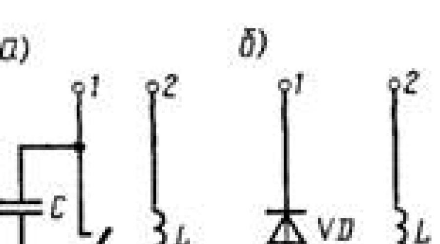
Rice. 2. Electrical circuits calls ZPT-12U1, ZPT-24U1 (a) and ZPT-80U1 (b)
1 Tolerance±15%. 
Electric bells (Table 2) are intended for acoustic signaling at railway crossings and in various stationary railway devices. Calls have closed design, which houses electromagnetic system(Fig. 2). Calls provide clear sound that can be heard at a distance of at least 80 m from the call.
Table 2. Electrical characteristics PTA calls
Call |
Supply current |
Supply voltage, V |
Current consumption, mA, no more |
Frequency, |
Coil resistance1, Ohm |
Constant |
|||||
Variable |
Temperature environment when operating calls it should be from -40 to 55 °C. Dimensions 171X130X115 mm; weight 0.97 kg.
DC calls. DC bells are designed for acoustic signaling of blown fuses, control of switches blown and other purposes in signaling and communication devices.
The electrical characteristics of the bells are given below:
Each bell has a spark arresting capacitor connected in parallel with the breaking contact.
A bell with an operating voltage of 3 V starts ringing at a voltage of 1.5 V. The sound strength created by DC bells is at least 60 dB. Bells must be used at air temperatures from 1 to 40 °C. Bell diameter 80 mm; height 50 mm; weight 0.26 kg.
Technology for servicing crossing alarm devices and car barriers
For execution technological processes When servicing crossing alarm devices and auto barriers, you must have a Ts4380 ampere-voltmeter, various kinds of tools and materials. The operation of automation devices should be checked both when the train passes through the crossing and when turned on from the control panel. In sections with large train intervals, automation devices can be switched on by shunting the track circuit of the approach section in the absence of trains.
The operation of automation devices at crossings is checked by an electrician and an electrician once every two weeks. At the same time, they check: the condition and adjustment of the commutator contacts and electric motor brushes; electric motor current when operating on friction; interaction of electric drive parts when opening and closing the barrier; the presence of a lubricant for the rubbing parts of the electric drive; proper operation of sound signals; visibility of crossing traffic lights and lamps on bars; frequency of flashing lights of crossing traffic lights; closing and opening barriers from the control panel; condition of contact springs and drive installation.
In the electric drive, the gearbox, auto-switch, contact block, installation, friction and shock-absorbing clutches are checked. An internal check of the electric drive, including cleaning and lubrication, should be carried out with the barriers closed. To prevent the bars from lifting, it is recommended to place a thin insulating plate between the working contacts through which the electric motor is turned on during the test.
Sound signals are checked while the crossing alarm is operating. With auto- and electric barriers, the bells on the masts of crossing traffic lights should start ringing simultaneously with the turning on of the traffic light alarm and turn off when the barrier beam drops to a horizontal position and the electric drive contacts included in the bell circuit open. For traffic lights without barriers, the bells must ring until the crossing is completely cleared by train. In pulsed power mode, calls should operate with a number of (40±2) switchings per minute.
The electrician must check the operation of all buttons installed on the panel, except for the “Enable the barrier” button. During the inspection, the crossing attendant presses and pulls the buttons, and the electrician observes the operation of the devices, turning Special attention to those buttons that the crossing officer on duty does not use under normal conditions.
The operation of the “Close” button at auto barriers is checked when there are no trains in the approach section. Pressing the “Close” button should turn on the traffic lights and sound alarm and closing the barriers. When the "Close" button is pulled, the alarm should turn off and the barriers should open.
The condition of the devices and installation of sound and light alarms, as well as the electric drive of the barrier with complete disassembly into individual components, is checked by an electrician together with an electrician once a year.
After disassembling the electric drive inner part the housings are cleaned of rust with a wire brush; All characteristics of the electric motor are checked separately, and if necessary, the electric drive is taken to remote workshops. When checking devices and installation of sound and light alarms, the state of the bells is determined by opening the installation leading to them. Perform internal and external checks of the condition of the heads of crossing traffic lights, lights of barrier bars of barriers.
Once a year, a senior electrician, together with an electrician, carefully checks the operation of automation devices at crossings and determines the need to replace individual components.
Classification of crossings and fencing devices
Railway crossings are called crossings highways with railway tracks on the same level. Moves are considered objects increased danger . The main condition for ensuring traffic safety is the following condition: railway transport has an advantage in traffic over all other modes of transport.
Crossings depending on the intensity of railway and road transport, and also depending on the category of roads are divided into four categories. Crossings with the highest traffic intensity are assigned category 1. In addition, category 1 includes all crossings in areas with train speeds of more than 140 km/h.
Moving happens adjustable(equipped with crossing signaling devices notifying vehicle drivers about the approach of a train crossing, and/or served by employees on duty) and unregulated. The possibility of safe passage through unregulated crossings is determined by the driver of the vehicle.
The list of crossings serviced by the employee on duty is given in the Operating Instructions railway crossings Ministry of Railways of Russia. Previously, such crossings were briefly called “guarded crossings”; By new Instructions and in this work – “moving with an attendant” or “attended moving”.
Crossing alarm systems can be divided into non-automatic, semi-automatic and automatic. In any case, a crossing equipped with a crossing alarm is protected by crossing traffic lights, and a crossing with a man on duty is additionally equipped with automatic, electric, mechanized or manual (horizontally rotating) barriers. At crossing traffic lights There are two red lamps located horizontally, which burn alternately when the crossing is closed. Simultaneously with the switching on of crossing traffic lights, acoustic signals are switched on. In accordance with modern requirements at certain crossings without an attendant, the red lights are supplemented white-moon fire. When the crossing is open, the white-moon light lights up in a flashing mode, indicating the serviceability of the APS devices; when closed, it does not light. When the white-moon lights are extinguished and the red lights are not burning, vehicle drivers must personally ensure that there are no approaching trains.
On railways Russia uses the following types of crossing alarms :
1. Traffic light signaling. Installed at crossings of access roads and other tracks where approach areas cannot be equipped with rail chains. A prerequisite is the introduction of logical dependencies between crossing traffic lights and shunting or specially installed traffic lights with red and moon-white lights that perform the functions of a barrier.
At crossings with an attendant, the crossing traffic lights are turned on by pressing a button on the crossing signaling panel. After this, the red light at the shunting traffic light goes out and the moon-white light turns on, allowing the movement of the railway rolling unit. Additionally, electric, mechanized or manual barriers are used.
At unmanned crossings, crossing traffic lights are supplemented by a white-lunar flashing light. The closing of the crossing is carried out by workers of the drafting or locomotive crew using a column installed on the mast of the shunting traffic light or automatically using track sensors.
2. Automatic traffic light signaling.
At unattended crossings located at hauls and stations, crossing traffic lights are controlled automatically under the influence of a passing train. Under certain conditions, for crossings located on a stretch, crossing traffic lights are supplemented with a white-lunar flashing light.
If the approach section includes station traffic lights, then their opening occurs with a time delay after the crossing is closed, providing the required notification time.
3. Automatic traffic light signaling with semi-automatic barriers. Used at serviced crossings at stations. The closing of the crossing occurs automatically when a train approaches, when setting a route at the station if the corresponding traffic light enters the approaching section, or forcefully when the station duty officer presses the “Closing Crossing” button. The lifting of the barrier bars and the opening of the crossing is carried out by the crossing duty officer.
4. Automatic traffic light signaling with automatic barriers. It is used at serviced crossings on stretches. Crossing traffic lights and barriers are controlled automatically.
In addition, warning alarm systems are used at stations. At warning alarm the crossing duty officer receives an optical or acoustic signal about the approach of the train and, in accordance with this, turns it on and off technical means crossing fencing.
Approach Section Calculation
To ensure unimpeded passage of the train, the crossing must be closed when the train approaches for a time sufficient for it to be cleared by vehicles. This time is called notification time and is determined by the formula
t and =( t 1 +t 2 +t 3), s,
Where t 1 – time required for the car to cross the crossing;
t 2 – equipment response time ( t 2 =2 s);
t 3 – guarantee time reserve ( t 3 =10 s).
Time t 1 is determined by the formula
 , With,
Where ℓ n – crossing length equal to the distance from the crossing traffic light to a point located 2.5 m from the opposite outer rail;
ℓ р – estimated length of the car ( ℓ p =24 m);
ℓ o – distance from the place where the car stops to the crossing traffic light ( ℓ o =5 m);
V p – the estimated speed of the vehicle through the crossing ( V p =2.2 m/s).
The notification time is at least 40 seconds.
When a crossing is closed, the train must be at a distance from it, which is called estimated length of the approach section
L p =0.28 V max t cm,
Where V max – maximum set speed train movement on this section, but not more than 140 km/h.
The approach of a train to a crossing in the presence of an AB is detected using existing automatic blocking control centers or using track overlay circuits. In the absence of AB, the areas approaching the crossing are equipped with track circuits. In traditional AB systems, the boundaries of the track circuits are located at the traffic lights. Therefore, the notification will be transmitted when the head of the train enters the traffic light. The estimated length of the approach section may be less or greater than the distance from the crossing to the traffic light (Fig. 7.1).
In the first case, the notification is transmitted over one approach section (see Fig. 7.1, odd direction), in the second - over two (see Fig. 7.1, even direction).

Rice. 7.1. Areas approaching the crossing
In both cases, the actual length of the approach section L f is more than calculated L p, because notification of the approach of a train will be transmitted when the head of the train enters the corresponding DC, and not at the moment it enters the calculated point. This must be taken into account when constructing crossing signaling schemes. The use of tonal RCs in AB systems or the use of superposition track circuits ensures equality L f = L p and eliminates this disadvantage.
Significant operational disadvantage of all existing automatic crossing alarm systems (AP) is fixed length of approach section, calculated based on the maximum speed in the section with the most high speed train. Enough large number sections maximum set speed passenger trains is 120 and 140 km/h. IN real conditions all trains travel at a slower speed. Therefore, in the vast majority of cases, the crossing is closed prematurely. Excessive time of the closed state of the crossing can reach 5 minutes. This causes delays for vehicles at the crossing. In addition, drivers of vehicles have doubts about the serviceability of the crossing alarm, and they may start driving when the crossing is closed.
The indicated disadvantage can be eliminated by introducing devices that measure the actual speed of the train approaching the crossing and forming a command to close the crossing taking into account this speed, as well as the possible acceleration of the train. In this direction, a number of technical solutions. However practical application they didn't find it.
Another disadvantage AP systems are an imperfect security procedure in case of an emergency at a crossing(a stopped car, a collapsed load, etc.). At crossings without an attendant, traffic safety in such a situation depends on the driver. At serviced crossings, the duty officer must turn on the traffic lights. To do this, he needs to turn his attention to the current situation, evaluate it, approach the control panel and press the appropriate button. It is obvious that in both cases there is no efficiency and reliability in detecting an obstacle to the movement of a train and accepting necessary measures. To solve this problem, work is underway to create devices for detecting obstacles at crossings and transmitting information about this to the locomotive. The task of detecting obstacles is implemented using a variety of sensors (optical, ultrasonic, high-frequency, capacitive, inductive, etc.). However, existing developments are not yet sufficiently advanced in technically and their implementation is not economically feasible.
Operating principle of UZP (Crossing Barrier Device)
The barrier device works as follows: when the drive electric motor is turned on, first the drive lock that held the cover in the lowered position falls off, then, under the influence of the counterweight and the drive gate, the ultrasonic cover is raised at an angle of 30; at the end of the lid lifting phase, the auto switch is triggered and the electric motor is turned off, preparing the power circuit for turning the electric drive back on. Barrier devices, like auto barriers, have dual control - automatic and non-automatic - pressing buttons on the APS panel. In both cases: turning on the signal lights, moving the barrier bars to horizontal (when closing) and vertical (when opening), the ultrasonic covers to the raised (obstructing) - lowered (allowing passage) positions are carried out by de-energizing and, accordingly, energizing the PV relay (in the APS control cabinet ) and its repeaters (in the SPD cabinet). The barrier device works as follows (see Appendix 8). When a train appears in the area approaching the crossing in the relay cabinet of the crossing alarm, the PV relay is de-energized, the PV1 relay is energized, the red flashing lights of the crossing traffic lights are turned on, the UZ cover zone vacancy monitoring system is turned on, and after about 13 s the VM relay is de-energized and the barrier bars begin to lower. From the moment the VM relay is de-energized in the UZP relay cabinet, the VUZ relay (UZ turn-on relay) is turned on, after about 3 s, the BVMSh delay unit is activated, and the relay for lifting the covers of the barrier UZ, UP and VUZM is activated. The friction relay F and the NPS relay are activated, the contacts of which control the ultrasonic drives. The activation of the PPS relay of each of the drives is possible provided that the zones of the ultrasonic covers are free. The control of the free zones of the ultrasonic protection covers is carried out by the front contacts of the safety protection relay, which receives power from the protection protection sensor. RN relays monitor the presence of voltage from the control outputs of the KZK sensors. After the PPS and NPS relays are triggered, power is supplied to the electric motors of the drives; within 4 s, the covers of the UZ occupy a blocking position, preventing vehicles from entering the crossing. The electric motors of the drives are turned off after lifting the ultrasonic covers by the working contacts of the autoswitch. In the case of the electric motors of the drives operating on friction (UZ covers cannot be raised or lowered due to the presence of an obstacle), the NPS relay and electric motors are turned off by the contacts of the friction relay F, which has a drop-off delay of 6 - 8 s. After the PPS and NPS relays are triggered, power is supplied to the electric motors of the drives; within 4 s, the covers of the UZ occupy a blocking position, preventing vehicles from entering the crossing. The electric motors of the drives are turned off after lifting the ultrasonic covers by the working contacts of the autoswitch. In the case of the electric motors of the drives operating on friction (UZ covers cannot be raised or lowered due to the presence of an obstacle), the NPS relay and electric motors are turned off by the contacts of the friction relay F, which has a drop-off delay of 6 - 8 s. The electric motors of the drives are powered from a rectifier device (BP) (VUS-1.3). In case of failure of the main rectifier device BP 1, the contacts of relay A2 switch to the backup rectifier device BP 2 (VUS-1,3). After the train has passed the crossing, the PV relay is excited in the APS relay cabinet and the VUZ relay is turned off in the UZP relay cabinet. The electric motors of the drives begin to work to lower the ultrasonic covers. After the covers are lowered, relays 1PK - 4PK are excited. With the control of the excitation of relays 1PK - 4PK, the relay circuit U1, U2 is closed in the APS relay cabinet, which also controls the raising of the barrier bars, and the red flashing lights of crossing traffic lights are turned off. The person on duty at the crossing also has the opportunity to bring the UZ covers into the blocking position or lower them. In the first case, he needs to press the “closing” button on the APS panel: in the APS cabinet the PV relay is de-energized, the crossing alarm devices are turned on, and in the UZP relay cabinet after 13 s the VUZ relay is triggered and, as in the case automatic feeding notification of the approach of a train, the UZ covers are lifted. To lower the UZ covers, you need to pull out this button. For emergency lowering of the UZ covers, you need to break the seal on the UZ panel with the “normalization” button and press it. The covers of all ultrasonic devices are lowered, and the ultrasonic device is switched off from operation. However, in this case, turning off the flashing red lamps of crossing traffic lights is carried out without controlling the lowering of the UZ covers. Also, a decision was made to eliminate the blinking of the red lamps of crossing traffic lights after pressing the “normalization” button in the event of loss of control of the position of the ultrasonic covers on the contacts of the autoswitches of the ultrasonic drives. The person on duty at the crossing, when pressing the “normalization” button, must make sure that the covers of the control unit are lowered and, if any cover is not in the lower position, finish the operation of the drive using the crank handle. On the UZP panel, to monitor the positions of the covers and the state of the KZK sensors, there are three rows of light bulbs (LEDs) with 4 light bulbs (LEDs) in a row. The top row signals through the control contacts of the drives about the raised, upper position of the covers, middle row through the front contacts of the relay 1PK-4PK - about the lower position of the covers, and the bottom row, with an even burning signal, indicates the working condition of the KZK sensors, and by blinking it indicates a sensor malfunction. If there is no train in the approaching section, the bottom row of lights (LEDs) does not light up. Three buttons are installed on the UZP panel: - two non-latching, non-sealable buttons, “exit 1” and “exit 3” - for lowering the covers of the first and third UZ, respectively, when vehicles exit the crossing; - button with fixation, sealable, “normalization” - for lowering the covers of the ultrasonic device and turning off the ultrasonic device from operation in the event of a malfunction. The control of the non-pressed position of the “normalization” button on the UZP panel is carried out by the lighting of the “normalization” light bulb (LED).
Railway crossings are the intersection of highways and railway tracks at the same level. Moving places are considered high-risk objects. The main condition for ensuring traffic safety at crossings is the following condition: railway transport has an advantage in traffic over all other modes of transport.
Depending on the intensity of railway and road transport traffic, as well as depending on the category of roads, crossings are divided into four categories. Crossings with the highest traffic intensity are assigned category 1. In addition, category 1 includes all crossings in areas with train speeds of more than 140 km/h.
Moving happens adjustable And unregulated. Regulated crossings include crossings equipped with crossing signaling devices that notify vehicle drivers about the approach of a train crossing, and/or serviced by employees on duty. The possibility of safe passage through unregulated crossings is determined by the driver of the vehicle independently in accordance with the Rules traffic Russian Federation.
The list of crossings serviced by the employee on duty is given in the Instructions for the operation of railway crossings of the Russian Ministry of Railways. Previously, such crossings were briefly called “guarded crossings”; according to the new Instructions and in this work – “moving with an attendant” or “attended moving”.
Crossing alarm systems can be divided into non-automatic, semi-automatic and automatic. In any case, a crossing equipped with a crossing alarm is protected by crossing traffic lights, and a crossing with a man on duty is additionally equipped with automatic, electric, mechanized or manual (horizontally rotating) barriers. At crossing traffic lights There are two red lamps located horizontally, which burn alternately when the crossing is closed. Simultaneously with the switching on of crossing traffic lights, acoustic signals are switched on. In accordance with modern requirements, at certain crossings without an attendant, the red lights of crossing traffic lights are supplemented white-moon fire. When the crossing is open, the white-moon light lights up in a flashing mode, indicating the serviceability of the devices; when closed, it does not light. When the white-moon light is extinguished and the red lights are not lit, vehicle drivers must personally ensure that there are no approaching trains.
The following are used on Russian railways: types of crossing alarms :
1. Traffic light signaling. Installed at crossings of access roads and other tracks where approach areas cannot be equipped with rail chains. A prerequisite is the introduction of logical dependencies between crossing traffic lights and shunting or specially installed traffic lights with red and moon-white lights that serve as barriers for railway rolling stock.
At crossings with an attendant, the crossing traffic lights are turned on by pressing a button on the crossing signaling panel. After this, the red light at the shunting traffic light goes out and the moon-white light turns on, allowing the movement of the railway rolling unit. Additionally, electric, mechanized or manual barriers are used.
At unmanned crossings, crossing traffic lights are supplemented by a white-lunar flashing light. The closing of the crossing is carried out by workers of the drafting or locomotive crew using a column installed on the mast of the shunting traffic light or automatically using track sensors.
2. Automatic traffic light signaling.
At unattended crossings located at hauls and stations, crossing traffic lights are controlled automatically under the influence of a passing train. Under certain conditions, for crossings located on a stretch, crossing traffic lights are supplemented with a white-lunar flashing light.
If the approach section includes station traffic lights, then their opening occurs after the crossing is closed with a time delay that ensures the required notification time.
3. Automatic traffic light signaling with semi-automatic barriers. Used at serviced crossings at stations. The closing of the crossing occurs automatically when a train approaches, when setting a route at the station if the corresponding traffic light enters the approaching section, or forcefully when the station duty officer presses the “Closing Crossing” button. The lifting of the barrier bars and the opening of the crossing is carried out by the crossing duty officer.
4. Automatic traffic light signaling with automatic barriers. It is used at serviced crossings on stretches. Crossing traffic lights and barriers are controlled automatically.
In addition to the listed devices, warning alarm systems are used at stations. At warning alarm The crossing duty officer receives an optical or acoustic signal about the approach of a train and turns on the technical means of fencing the crossing. After the train has passed, the attendant opens the crossing.