Arduino uno 4 digit 7 segment indicator. Seven-segment indicator. Number of connected indicators
Read also
Seven-segment LED indicators are very popular among digital value display devices and are used in front panels microwave ovens, washing machines, digital watch, counters, timers, etc. Compared to LCD indicators, the segments of the LED indicator glow brightly and are visible on long distance and at a wide viewing angle. To connect a seven-segment 4-bit indicator to a microcontroller, at least 12 I/O lines will be required. Therefore, it is almost impossible to use these indicators with microcontrollers with a small number of pins, for example, series from the company. Of course you can use different methods multiplexing (a description of which can be found on the website in the “Schemes” section), but even in this case there are certain limitations for each method, and they often use complex software algorithms.
We will look at the method of connecting an indicator via the SPI interface, which will require only 3 I/O lines of the microcontroller. At the same time, control of all indicator segments will remain.
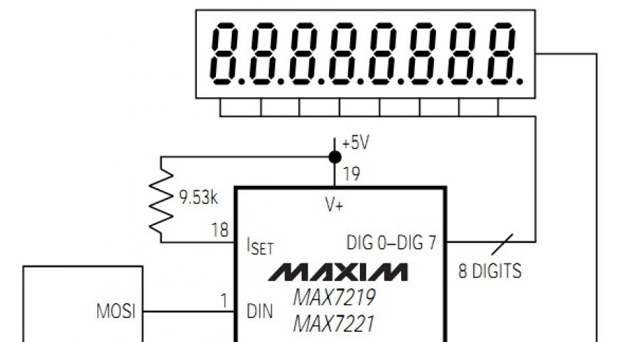
To connect a 4-bit indicator to a microcontroller via the SPI bus, a specialized driver chip produced by the company is used. The microcircuit is capable of driving eight seven-segment indicators with a common cathode and includes a BCD decoder, segment drivers, a multiplexing circuit and static RAM for storing digit values.
The current through the indicator segments is set using only one external resistor. Additionally, the chip supports control of indicator brightness (16 brightness levels) using built-in PWM.
The circuit discussed in the article is a circuit of a display module with an SPI interface that can be used in amateur radio designs. And we are more interested not in the circuit itself, but in working with the microcircuit via the SPI interface. The +5 V module power is supplied to the Vcc pin, the MOSI, CLK and CS signal lines are intended for communication between the master device (microcontroller) and the slave (MAX7219 chip).
The microcircuit is used in a standard connection; the only external components needed are a resistor that sets the current through the segments, a protective diode for the power supply, and a filter capacitor for the power supply.

Data is transferred to the chip in 16-bit packets (two bytes), which are placed in the built-in 16-bit shift register on each rising edge of the CLK signal. We denote a 16-bit packet as D0-D15, where bits D0-D7 contain data, D8-D11 contain the register address, bits D12-D15 have no meaning. Bit D15 is the most significant bit and is the first bit received. Although the chip is capable of controlling eight indicators, we will consider working with only four. They are controlled by the outputs DIG0 - DIG3, located in sequence from right to left, the 4-bit addresses (D8-D11) that correspond to them are 0x01, 0x02, 0x03 and 0x04 (hexadecimal format). The digit register is implemented using on-chip RAM with an 8x8 organization and is directly addressable so that each individual digit on the display can be updated at any time. The following table shows the addressable digits and control registers of the MAX7219 chip.
|
Register |
Address |
HEX value |
||||
|
No operation |
||||||
|
Decoding Mode |
||||||
|
Number of indicators |
||||||
|
Shutdown |
||||||
|
Indicator test |
||||||
Control registers
The MAX1792 chip has 5 control registers: decoding mode (Decode-Mode), indicator brightness control (Intensity), register of the number of connected indicators (Scan Limit), on/off control (Shutdown), test mode (Display Test).
Turning the chip on and off
When power is applied to the chip, all registers are reset and it goes into Shutdown mode. In this mode the display is turned off. To switch to normal operation mode, bit D0 of the Shutdown register (address 0Сh) must be set. This bit can be cleared at any time to force the driver to turn off, leaving the contents of all registers unchanged. This mode can be used to save energy or in alarm mode by flashing the indicator (sequential activation and deactivation of the Shutdown mode).
The microcircuit is switched to Shutdown mode by sequentially transmitting the address (0Сh) and data (00h), and transferring 0Ch (address) and then 01h (data) returns to normal operation.
Decoding mode
Using the decoding mode selection register (address 09h), you can use BCD code B decoding (display characters 0-9, E, H, L, P, -) or without decoding for each digit. Each bit in the register corresponds to one digit, setting a logical one corresponds to turning on the decoder for this bit, setting 0 means the decoder is disabled. If a BCD decoder is used, then only the lowest nibble of data in the digit registers (D3-D0) is taken into account, bits D4-D6 are ignored, bit D7 does not depend on the BCD decoder and is responsible for turning on the decimal point on the indicator if D7 = 1. For example, when bytes 02h and 05h are sent in sequence, the DIG1 indicator (second digit from the right) will display the number 5. Similarly, when sending 01h and 89h, the DIG0 indicator will display the number 9 with the decimal point included. The table below shows full list characters displayed when using the chip's BCD decoder.
|
Symbol |
Data in registers |
Enabled segments = 1 |
||||||||||||
| — | ||||||||||||||
|
Empty |
||||||||||||||
|
*The decimal point is set by bit D7=1 |
||||||||||||||
When the BCD decoder is excluded from operation, data bits D7-D0 correspond to the segment lines (A-G and DP) of the indicator.

Indicator brightness control
The chip allows you to programmatically control the brightness of the indicators using the built-in PWM. The PWM output is controlled by the low-order nibble (D3-D0) of the Intensity register (address 0Ah), which allows you to set one of 16 brightness levels. When all bits of a nibble are set to 1, the maximum brightness of the indicator is selected.
Number of connected indicators
The Scan-Limit register (address 0Bh) sets the value of the number of bits serviced by the microcircuit (1 ... 8). For our 4-bit version, the value 03h should be written to the register.
Indicator test
The register responsible for this mode is located at address 0Fh. By setting the D0 bit in the register, the user turns on all indicator segments, while the contents of the control and data registers do not change. To disable Display-Test mode, bit D0 must be 0.
Interface with microcontroller
The indicator module can be connected to any microcontroller that has three free I/O lines. If the microcontroller has a built-in SPI hardware module, then the indicator module can be connected as a slave device on the bus. In this case, the SPI signal lines SDO (serial data out), SCLK (serial clock) and SS (slave select) of the microcontroller can be directly connected to the MOSI, CLK and CS pins of the MAX7219 chip (module), the CS signal is active low.
If the microcontroller does not have hardware SPI, the interface can be organized in software. Communication with the MAX7219 chip begins with insertion and retention low level on the CS line, after which 16 bits of data are sent sequentially (most significant bit sent first) along the MOSI line on the rising edge of the CLK signal. Upon completion of the transmission, the CS line goes high again.
In the downloads section, users can download the source text of the test program and the HEX file of the firmware, which implements a conventional 4-bit counter with display of values on an indicator module with an SPI interface. The microcontroller used is an interface implemented in software, the signal lines CS, MOSI and CLK of the indicator module are connected to ports GP0, GP1 and GP2, respectively. The mikroC compiler for PIC microcontrollers is used (mikroElektronika
To comment on materials from the site and gain full access to our forum, you need register . |
Good day! After my long and forced break, we will continue mastering the Arduino Programming course. In one of our previous lessons, we already worked with a sequence of LEDs, now it's time to move on to the next stage of training. The topic of today's article will be - 7- segment indicator.
Getting to know the 7-segment indicator will consist of two parts. In the first part, we will briefly go over the theoretical component, work with the hardware and write simple programs.
Last time we worked with a sequence of 8 LEDs, today there will also be 8 of them (7 LED strips and 1 dot). Unlike the previous sequence, the elements of this set are not lined up (one after another), but are arranged in a certain order. Thanks to this, using only one component you can display 10 digits (from 0 to 9).
Another significant difference that sets this indicator apart from simple LEDs. It has a common cathode (or rather, two equivalent legs 3 and 8, on which the cathode is connected). It is enough just to connect one of the cathodes to ground ( GND). All indicator elements have individual anodes.
A small digression. All of the above applies to 7-segment indicators with a common cathode. However, there are indicators with a common anode. Connecting such indicators has significant differences, so please do not confuse “sinful with righteous.” You need to clearly understand what type of seven-segment device you have in your hands!
In addition to the differences between simple LEDs and 7-segment indicators, there are also common features. For example: indicators, like LEDs, can be mounted in a row (sequence) to display two-, three-, four-digit numbers (digits). However, I don’t advise you to worry too much about self-assembly segment sets. On sale “next to” single-digit indicators, multi-digit indicators are also sold.
I hope you haven't forgotten about the need to use current-limiting resistors when connecting LEDs. The same applies to indicators: each element of the indicator must have its own resistor connected. 8 elements (7 + 1) – 8 resistors.
I had at hand a seven-segment unit marked 5161AS (common cathode). Pinout:


Schematic diagram

As I said earlier, in order to turn on segment “A”, we connect ground to any common pin (3 or 8), and supply 5V power to pin 7. If the indicator has a common anode, then we apply 5V to the anode and ground to the output of the segment!
Let's assemble a test stand. We connect the wires in order, starting with the first leg, which goes to the 2nd pin of the Arduino board. We connect the ground to pin 8 of the indicator.

After the stand is assembled, you can start writing the firmware.
To check the indicator, let's run the written program. Let’s select element “A” and flash it.

Now let's flash the number 2. To do this, let's turn on a few more elements.

To output one digit, you need to write n-number of lines of code. It’s difficult, don’t you think?
There is another way. In order to display any number on the indicator, it must first be represented as a certain sequence of bits.
Table of correspondence.

If the display has a common anode, then 1 must be replaced with 0, and 0 with 1!
The hex column is a representation of a number in byte form (we'll talk about this in more detail in the second part).
A number in the binary number system is written as follows: 0b00000000. 0b- binary system. Zeros mean all LEDs are off.
When connecting, we used pins 2 to 9. To turn on pin 2, write one to it = 0b00000001. The fourth bit from the right is responsible for the dot. The very last bit corresponds to the line in the middle of the indicator.
Let's write an example of outputting the number 0.

To reduce the number of typed lines, we will use a loop that allows you to “iterate” all 8 bits. Variable Enable_segment the value of the read bit is assigned. After this, the current output is set to the appropriate mode ( presence or absence of signal).
Note: The bitRead() function reads the state of the specified bit and returns the state value (0 or 1).bitRead(x, n)where x is the number whose bits need to be read; n is the number of the bit whose state needs to be read. Numbering starts with the least significant (rightmost) bit numbered 0.
And at the end of the first part we will write a small counter.

Connecting a seven-segment display to an Arduino is a great project entry level, allowing you to get to know the Arduino board better. But it's quite easy to do. Therefore, we will complicate the task somewhat and connect a four-digit seven-segment indicator.
IN in this case We will use a four-digit LED indicator module with a common cathode.
Each segment in the indicator module is multiplexed, meaning it shares one anode connection point with other segments of its discharge. And each of the four bits in the module has its own connection point with a common cathode. This allows each digit to be turned on or off independently. Additionally, this multiplexing method allows the microcontroller to use only eleven or twelve pins instead of thirty-two.
LED segments of the indicator require the connection of current-limiting resistors when powered from 5 V to logical conclusion. The resistor value is usually taken between 330 and 470 ohms. It is also recommended to use transistors to provide additional current, since each pin of the microcontroller can supply a maximum of 40 mA. If you turn on all the discharge segments (number 8), the current consumption will exceed this limit. The figure below shows a connection diagram for a four-digit seven-segment indicator using current-limiting resistor transistors.

The following are diagrams for connecting the indicator to the Arduino pins. Bipolar NPN transistors BC547 are used here. A 10 KOhm potentiometer connected to the input of the A0 board allows you to change the value displayed on the indicator from 0 to 1023.


On the Arduino board, digital outputs D2-D8 in this case are used to control segments “a” to “g”, and digital outputs D9-D12 are used to control bits D0 to D3. It should be noted that in this example the dot is not used, but in the sketch below it is possible to use it. Pin D13 of the Arduino board is reserved for controlling the point segment.

Below is the code that allows you to control a four-digit segment indicator using an Arduino board. In it, the numeral array specifies the codes of numbers from 0 to 9 in binary form. This sketch supports both indicators with a common cathode (by default) and indicators with a common anode (to do this, you need to uncomment one line at the end of the sketch).
// bits representing segments A through G (and dots), for numbers 0-9 const int numeral = ( //ABCDEFG /dp B11111100, // 0 B01100000, // 1 B11011010, // 2 B11110010, // 3 B01100110, // 4 B10110110, // 5 B00111110, // 6 B11100000, // 7 B11111110, // 8 B11100110, // 9 ); // pins for the point and each segment // DP,G,F,E,D,C,B,A const int segmentPins = ( 13,8,7,6,5,4,3,2 ); const int nbrDigits= 4; // number of digits of the LED indicator // digits 0 1 2 3 const int digitPins = ( 9,10,11,12 ); void setup() ( for(int i=0; i< 8; i++) { pinMode(segmentPins[i], OUTPUT); // устанавливаем выводы для сегментов и точки на выход } for(int i=0; i < nbrDigits; i++) { pinMode(digitPins[i], OUTPUT); } } void loop() { int value = analogRead(0); showNumber(value); } void showNumber(int number) { if(number == 0) { showDigit(0, nbrDigits-1) ; // отображаем 0 в правом разряде } else { // отображаем значение, соответствующее каждой цифре // крайняя левая цифра 0, правая на единицу меньше, чем число позиций for(int digit = nbrDigits-1; digit >= 0; digit--) ( if(number > 0) ( showDigit(number % 10, digit) ; number = number / 10; ) ) ) ) // Display the given number on this category 7-segment indicator void showDigit(int number, int digit) ( digitalWrite(digitPins, HIGH); for(int segment = 1; segment< 8; segment++) { boolean isBitSet = bitRead(numeral, segment); // isBitSet будет истинным, если данный бит будет 1 // isBitSet = ! isBitSet; // опционально // раскомментируйте опциональную строчку выше для индикатора с общим анодом digitalWrite(segmentPins, isBitSet); } delay(5); digitalWrite(digitPins, LOW); }
Connection diagram for a one-digit seven-segment indicator
Connection diagram for a multi-digit seven-segment indicator
Digital information display device. This is the most simple implementation indicator that can display Arabic numerals. More complex multi-segment and matrix indicators are used to display letters.
As its name says, it consists of seven display elements (segments) that turn on and off separately. Including them in different combinations, from them you can create simplified images of Arabic numerals.
The segments are designated by letters A through G; eighth segment - decimal point
(decimal point, DP), designed to display fractional numbers.
Occasionally, letters are displayed on the seven-segment indicator.


There are different colors, usually the colors are white, red, green, yellow and blue. In addition, they can be of different sizes.
Also, the LED indicator can be single-digit (as in the figure above) or multi-digit. Basically, one-, two-, three- and four-digit LED indicators are used in practice:

In addition to ten digits, seven-segment indicators are capable of displaying letters. But few letters have an intuitive seven-segment representation.
In Latin: capital A, B, C, E, F, G, H, I, J, L, N, O, P, S, U, Y, Z, lowercase a, b, c, d, e, g , h, i, n, o, q, r, t, u.
In Cyrillic: A, B, V, G, g, E, i, N, O, o, P, p, R, S, s, U, Ch, Y (two digits), b, E/Z.
Therefore, seven-segment indicators are used only to display simple messages.
In total, the seven-segment LED indicator can display 128 characters:

A typical LED indicator has nine leads: one goes to the cathodes of all segments, and the other eight go to the anode of each segment. This scheme is called "common cathode circuit", there are also schemes with common anode(then it's the other way around). Often, not one, but two common terminals are made at different ends of the base - this simplifies the wiring without increasing the dimensions. There are also so-called “universal” ones, but I personally have not encountered such ones. In addition, there are indicators with a built-in shift register, which greatly reduces the number of microcontroller port pins involved, but they are much more expensive and are rarely used in practice. And since the immensity cannot be grasped, we will not consider such indicators for now (but there are also indicators with much big amount segments, matrix).
Multi-digit LED indicators often work on a dynamic principle: the outputs of the segments of the same name of all digits are connected together. To display information on such an indicator, the control microcircuit must cyclically supply current to the common terminals of all digits, while current is supplied to the segment terminals depending on whether a given segment is lit in a given digit.


Connecting a one-digit seven-segment indicator to a microcontroller
The diagram below shows how a single-digit seven-segment indicator is connected to the microcontroller.
It should be taken into account that if the indicator with COMMON CATHODE, then its common output is connected to "earth", and the segments are ignited by feeding logical unit to the port output.
If the indicator is COMMON ANODE, then it is supplied to its common wire "plus" voltage, and the segments are ignited by switching the port output to the state logical zero.
 Indication in a single-digit LED indicator is carried out by applying a binary code to the pins of the microcontroller port of the corresponding digit of the corresponding logical level (for indicators with OK - logical ones, for indicators with OA - logical zeros).
Current limiting resistors may or may not be present in the diagram. It all depends on the supply voltage that is supplied to the indicator and technical characteristics indicators. If, for example, the voltage supplied to the segments is 5 volts, and they are designed for operating voltage 2 volts, then it is necessary to install current-limiting resistors (to limit the current through them for an increased supply voltage and not to burn not only the indicator, but also the microcontroller port).
It is very easy to calculate the value of current-limiting resistors, using the grandfather’s formula Ohm.
For example, the characteristics of the indicator are as follows (taken from the datasheet):
— operating voltage — 2 volts
— operating current — 10 mA (=0.01 A)
— supply voltage 5 volts
Formula for calculation:
R= U/I (all values in this formula must be in Ohms, Volts and Amps)
R= (supply voltage - operating voltage)/operating current
R= (5-2)/0.01 = 300 Ohm
Connection diagram for a multi-digit seven-segment LED indicator Basically the same as when connecting a single-digit indicator. The only thing is that control transistors are added in the cathodes (anodes) of the indicators:

It is not shown in the diagram, but between the bases of the transistors and the pins of the microcontroller port, it is necessary to include resistors, the resistance of which depends on the type of transistor (the resistor values are calculated, but you can also try using resistors with a nominal value of 5-10 kOhm).
Indication by discharges is carried out dynamically:
— the binary code of the corresponding digit is set at the outputs of the PB port for the 1st digit, then the logical level is applied to the control transistor of the first digit
— the binary code of the corresponding digit is set at the outputs of the PB port for the 2nd digit, then the logical level is applied to the control transistor of the second digit
— the binary code of the corresponding digit is set at the outputs of the PB port for the 3rd digit, then the logical level is applied to the control transistor of the third digit
- so in a circle
In this case, it is necessary to take into account:
— for indicators with OK control transistor structure is used NPN(controlled by logical unit)
- for indicator with OA- structure transistor PNP(controlled by logic zero)
This time, the article will consider one of the most interesting modules, namely - multi-digit seven-segment indicator based on the MAX7219 chip. Why multi-bit? The answer is simple - the number of digits is the number of digits that the module can display. For example, in the photo below, three types of multi-digit indicators are shown, from left to right - 4-digit, 6-digit, 8-digit. Moreover, the first one is 4-digit dial indicator. The difference between a dial indicator and a regular one is that it has a sign colons, whereas in any regular indicator this sign is replaced by a dot at the bottom, next to the number.

In this article, the modules in question operate on the basis of a microcircuit MAX7219. This chip is a driver for seven-segment LED indicators, as well as 8x8 LED matrices, and we will not consider circuit diagrams connecting this driver. Just taken as a basis ready module, examples of connection to the board will be given Arduino UNO and worked with library functions LedControl. By the way, as already mentioned, 8x8 LED matrices also work based on a driver MAX7219, and if anyone is interested, welcome to the articles:
So, let's begin... I think that it was given about multi-bit good description, and here's why seven-segment? The answer is also not so complicated - because seven LEDs, indexed by letters, are used to form a symbol or display a number A, B, C, D, E, F, G, The table below shows how this is indicated:

As can be seen from the table, there is also an eighth LED - D.P. You can completely encode a character or digit in 1 byte by setting or clearing a specific bit, as shown with the character encoding example J. In the example the bits are set B, C, D, E, which allows you to display a specified character on a seven-segment indicator.
From theory to practice - let's connect an 8-bit module to the Arduino Uno board according to the diagram below:

To display symbols, several functions from the LedControl.h plug-in library are used. Let's look at each of these functions in order, starting with the setDigit() function.
The prototype of the function declaration for displaying the number and the arguments passed to the function:
setDigit(int addr, int digit, byte value, boolean dp);
Where -
int addr -module address on the busSPI 0 SPI starts from scratch)
int digit - 0 , 7
byte value -value (a number from 0 to 9) that needs to be displayed in the digit whose number is specified in the int digit parameter
boolean dp - int digit. If the parameter is true then the point will be displayed if false then the point will not be displayed.
The prototype of the function declaration for displaying the symbol and the arguments passed to the function:
setChar(int addr, int digit, char value, boolean dp);
int addr - module address on the busSPI for which the function is called, if there is only one module, then this parameter is equal to0 (default addressing of devices on the busSPI starts from scratch)
int digit - the serial number of the digit in the display module; by default, for multi-digit indicators, the numbering of digits begins with the rightmost digit, respectively, the number of the rightmost digit is equal to0 , and the number of the leftmost digit in our case is equal to7
char value - the character that should be displayed in the digit whose number is specified by the parameterint digit
boolean dp - this parameter is responsible for displaying a dot at the digit whose number is specified in the parameter int digit. If the parameter is true then the point will be displayed if false then the point will not be displayed.
A separate point worth mentioning is that the function setChar() can only display a limited set of characters, such as:
- 0 1 2 3 4 5 6 7 8 9 the digit is displayed as a symbol
- A a
- B b
- With with the character will be displayed in lower case
- D d the character will be displayed in lower case
- E e the character will appear in uppercase
- F f the character will appear in uppercase
- H h the character will be displayed in lower case
- Ll the character will appear in uppercase
- P p the character will appear in uppercase
- - minus sign"
- . , point display
- _ underscore
- <Пробел> set space character
In a test sketch, you can set a task like this:
- Display numbers from 1 to 8 one by one without a dot
- Fill in all the digits of the display module with numbers from 1 to 8, plus display all the points of the indicated digits
- Draw a bitwise array with characters pre-encoded in binary code, the result should be “Arduino rules!!!”
Due to the limited character set, the function setChar() is not suitable for a test sketch, since it will not be able to normally draw the phrase specified in point 3. Instead of this function, we will use the function setRow(). So... function setRow() has already been tested by us in articles about studying Led matrices 8x8, let's again describe the call prototype and parameters of this function.
Function Declaration Prototype setRow() and the arguments passed to the function:
setRow(int addr, int row, byte value);
int addr - module address on the busSPI for which the function is called, if there is only one module, then this parameter is equal to0 (default addressing of devices on the busSPI starts from scratch)
int row - the serial number of the digit in the display module; by default, for multi-digit indicators, the numbering of digits begins with the rightmost digit, respectively, the number of the rightmost digit is equal to0 , and the number of the leftmost digit in our case is equal to7
byte value- a value in binary format (example B00000000, alternatives in decimal and hexadecimal are also possible), which encodes the required character. The character encoding table will help you correctly encode the desired character.
Well, at the end of the article, a test sketch and a video of how it works:
#include "LedControl.h" /* * Include the LedControl.h library * and create an object of the LedControl class * in this case, a 7-segment display with a MAX72xx driver * must be connected to the Arduino board as follows: * Arduino -> Display Module MAX72xx * Arduino -> Display Module MAX72xx * Arduino -> Display Module MAX72xx * Arduino -> Display Module MAX72xx * Arduino -> Display Module MAX72xx * */ LedControl lc = LedControl(12, 11, 10, 1); //Array with encoded characters, //Phrase "Arduino ruLES!!!" Byte AR = (b0111101111, // A b00000101, // R B001111101, // D B00011100, // U B00010000, // I B00010101, // N B000111101, // O B00000101, // R B0001111100, // U B00001100 , //l B01001111, //E B01011011, //S B10110000, //! B10110000, //! void setup() ( //The device (7-segment display) is brought out of sleep mode lc.shutdown(0, false); //Set the display brightness to 8 //Total possible brightness modes from 0 to 15 lc.setIntensity(0 ,8); //Clear the display lc.clearDisplay(0); void loop() ( //The simplest iteration of numbers from 1 to 8 by digits for(int i = 0, j = 7; i< 8, j >= 0; i++, j--) ( lc.setDigit(0, j, byte(i + 1), false); delay(400); lc.clearDisplay(0); ) //Iterate through numbers without clearing the screen for(int i = 0, j = 7;< 8, j >= 0; i++, j--) ( lc.setDigit(0, j, byte(i + 1), true); delay(400); ) lc.clearDisplay(0); //Rendering the phrase "Arduino ruLES!!!" int n = 0; for(int i = 0; i< 2; i ++) { for(int j = 7; j >= 0; j --) ( if(n > 6 && !(i % 2)) ( continue; ) else ( lc.setRow(0, j, ar[n]); delay(400); n ++; ) ) lc .clearDisplay(0); ) delay(400); lc.clearDisplay(0); )