Algorithms for designing technological operations
Read also
Synthesis automation issues technological processes long years remain the focus of attention of researchers and developers of SAPRTP components. This is quite justified, since it is the synthesis of structure that is the most difficult to formalize process when creating design systems.
It should be noted that in terms of developing a methodology for automating the synthesis of routing technologies, there are significant results that make it possible to create fully operational CAD TP components. Currently, route synthesis is mainly used general technologies built on the basis of elementary routes, production lists or semantic networks. The use of artificial neural networks makes it possible to create a general process based on the principles of self-learning CAD TP, which simplifies and reduces the cost of adapting the system to specific production conditions.
In developing methods for automating the synthesis of operational technologies, successes are not so obvious. In the process of synthesis of operating technology, too many parameters are involved, including accuracy and dimensional parameters - dimensions of the part and workpiece, technological and adjustment dimensions, deviations in the shape and location of surfaces, allowances, etc.
The number of possible options for sizing schemes, both in the drawings of the part and workpiece, and in operational sketches, is so large that it is very difficult to take into account at all stages of system training.
This significantly complicates the work of a specialist adapting the system in relation to the traditions and capabilities of the production environment of a particular enterprise. So the techniques used in route synthesis and operating with a limited number of parameters are not very effective here, and in some cases they are simply not applicable.
As is known, the criterion for the quality of related dimensional chains of a synthesized operating technology is dimensional analysis. Dimensional analysis methods have now been developed to a sufficient extent for practical application, although some aspects require clarification or development.
As follows from the experience of dimensional analysis of technology, it is quite difficult, almost impossible, on the first attempt to create a process structure that meets all the requirements of the design document and ensures positive results of dimensional analysis.
In the process of synthesis of operating technology, it is necessary to be able not only to create a single version of the operation structure, but also to modify the structure based on the results of dimensional analysis. The mechanism of modification (resynthesis) of the structure has not been practically developed to date.
Another problem of structural synthesis of a technological operation arises when preparing initial information. Obviously, it is advisable to obtain most of the data related to the geometry of the part and its parameters from the design design system. This eliminates subjective errors typical for entering large volumes of data, and does not require the inclusion of linguistic support in the technological CAD system to describe the part and means of its interpretation, which usually complicates and increases the cost software. But when creating a two-dimensional drawing, most graphic editors operate with primitives such as segment, circle, arc, etc., which are almost impossible to correlate with the structural elements of the operation and route. Even with a three-dimensional model, significant difficulties arise.
Almost all graphic systems represent a part model, a workpiece model and operational sketches in the form of separate, unrelated graphic objects (drawings, fragments or three-dimensional models). In this regard, insurmountable difficulties arise in automatically identifying dimensional relationships, on the basis of which
synthesis of the structure of the technological process and its dimensional analysis.
Thus, to create a methodology for synthesizing operational technology for machining parts, it is necessary, at a minimum, to solve the following problems:
- develop a model of the design object that meets the requirements of technology synthesis and dimensional analysis;
- develop procedures for synthesizing the structure of the technological process using the results of dimensional analysis;
- clarify and supplement the methodology for dimensional analysis of the technological process.
The technological process editor RTP2000 allows you to create operational technology using conventional means based on the experience of a technologist or based on the use of analogue technologies. However, this is not the most effective method, since the quality of received design solutions here is largely determined by the qualifications of the project executor.
The best results are obtained by the method of using general operations, which allows you to synthesize operational technologies in an automatic mode on the basis of pre-developed information support, which allows you to obtain design solutions that are close to optimal.
The information basis for automatic technology synthesis is:
- library of form elements;
- library of standard technological operations.
For example, the geometry of a part, created using a library of form elements, makes it possible to ensure an unambiguous correspondence between the geometry of the part and technological transitions, and provide automatic generation of operational sketches and dimensional analysis. The system allows the transformation of a part drawing made using a conventional graphic editor, such as Compass, into an internal representation based on a library of form elements.
A library of standard technological operations (TTO) is developed in relation to the conditions of a specific enterprise, taking into account the traditions of designing operations. TTO operations can be used as part of general technological processes or individually.
A library operation contains an ordered set of transitions, each of which is associated with one or a complex of part shape elements.
In the process of applying TTO, the system checks the presence of the corresponding form element in the part. If it is absent, the transition is not included in a single technology. Otherwise, one or a certain number of transitions are generated (according to the number of form elements).
Thus, the composition of transitions for each operation is automatically formed from the general technological process. At the next stage, the process of technology synthesis is carried out based on evolutionary approach, which involves the sequential application of route stages with the analysis of dimensional relationships to assess the possibility of achieving the specified accuracy and other parameters of the part at each stage. The evolutionary process ends when the required part parameters are achieved.
At this stage, the dimensional analysis mechanism plays a fundamental role. Due to the fact that the variety of possible geometric shapes of a part does not allow us to provide in advance all schemes for setting technological dimensions, dimensional schemes are generated using a genetic algorithm. It allows you to quickly find acceptable operational sizing schemes for each operation that satisfy the requirements of dimensional analysis.
On final stage operational sketches of operations and a drawing of the workpiece are automatically generated.
Description of design objects
1. Structural model
The part model is developed based on the requirements of the task:
- the model should allow a convenient and simple description of characteristics characteristic of mechanical engineering parts geometric shapes;
- the model must be convenient for importing and exporting images using the most common graphics data exchange standards, such as DXF or KSF;
- elements of the model must provide an unambiguous connection with operations and transitions of the technological process;
- the model must provide an unambiguous connection between the dimensions of the part, the workpiece and the operational dimensions;
- the model should make it possible to automatically identify dimensional relationships, perform dimensional analysis and perform resynthesis of the technological process.
The model is based on the ideas presented in the work. The description of the geometry is carried out using a library of form elements (EF), forming the outer - main contour of the part, and auxiliary elements (EA), superimposed on the EF, taking into account the type of part.
The type of part is determined based on the kinematic approach and is specified by the method of obtaining the surface that forms the main contour of the part:
- a rotating part (shaft, bushing, disk, etc.) is formed by rotating the generatrix relative to the main axis of the part;
- the drawing part (bar, body, plate, etc.) is formed by moving the generatrix relative to the coordinate direction.
The structure of the geometry is determined by the type of part (due to limited volume, in the future we will consider only rotation parts) and includes:
- object (part, workpiece, operational sketch);
- coordinate direction specified for each object by the visualization plane (the number of directions is arbitrary, sufficient to describe the part).
Each coordinate direction includes a description:
- main circuit;
- additional circuits (the number of additional circuits is not limited).
A sign of the beginning of the contour description is the coordinate system (CS).
Within each circuit, the structure is divided into sections:
- EF section (starts with SK);
- EV section;
- section of coordinating sizes.
Each EF contains a list of parameters necessary for the synthesis of the technological process:
- quality;
- roughness parameter;
- roughness parameter value;
- type of shape deviation parameter;
- shape deviation parameter value;
- type of surface position deviation parameter;
- surface position deviation parameter value;
- type of heat treatment;
- heat treatment layer thickness;
- hardness scale;
- hardness value;
- type of coating;
- coating thickness;
- type of chemical heat treatment;
- thickness of the chemical-thermal treatment layer;
- type of additional processing.
The entire part (including the coordinate systems of additional contours) is described in the coordinate system of the main contour.
EFs within a section are ordered (sorted) by the value of the anchor coordinate to the origin of the contour (to the origin of the coordinate system). When sorting, the position indicator is determined (left, middle, right). The sign is recorded in the EF.
The EFs are not sorted (placed in the order in which they were recorded), but are associated with the EFs on which they are formed, two-way communication. The binding of the VF is carried out taking into account the sign of its position - closest or remote relative to the beginning of the SC. The position sign allows you to orient the EV. The remote position binds the EV to the right side of the EF with a rotation of 180. For each EF, a list of acceptable EVs is established.
EFs and EFs are called by their original names - identifiers, which are assigned to each new EF automatically using an identifier generator. The ID is represented as an integer and is used to identify the surfaces involved in the dimensional analysis.
Some EFs are systemic. They are determined automatically by the system when creating the main EFs. An example of a system element is the end of a step.
The first stage of TP design is the development of a preliminary design, the second is the development of working technological documentation at the stage prototype(batch), installation series, established serial or mass production.
The preliminary design is intended for testing and testing the manufacturability of the product design at the stages of preliminary and technical projects for the development of design documentation, for the preparation and development of working documentation.
Working technological documentation means a set of technological documents (maps, instructions, statements) that contain all the data necessary for the manufacture and control of the product.
Technological processes are divided into the following types:
· Design TP carried out according to a preliminary draft of technological documentation.
· Worker TP carried out according to working technological and design documentation.
· Unit TP relating to products of the same name, standard size and design, regardless of the type of production.
· Typical TP, which is characterized by the unity of content and sequence of most technological operations and transitions for a group of products with common design features.
· Standard TP is a technological process established by the standard.
· Temporary TP used at an enterprise for a limited period of time due to the lack of appropriate equipment or due to an accident until replacement with a more modern one.
· Perspective TP that corresponds to modern achievements of science and technology, the methods and means of implementation of which must be fully or partially mastered at the enterprise.
· Route
· Operating TP performed according to documentation in which the content of operations is stated, indicating transitions and processing modes.
· Route and operational TP performed according to documentation in which the content of operations is stated without indicating transitions and processing modes.
· Group TP, which is developed not for one part, but for a group of parts that are similar in technological characteristics.
Complex of works on design of technological processes
Technological processes are developed for products whose design has been tested for manufacturability and includes a set of interrelated works, which include:
· selection of blanks;
· selection of technological bases;
· selection of a standard technological process;
· determination of the sequence and content of technological operations;
· identification, selection and ordering of new technological equipment (including control and testing tools);
· purpose and calculation of processing modes;
· standardization of the process;
· selection of means of mechanization and automation of elements of technological processes and intra-shop means of transportation and others.
When developing technological processes, classifiers of technological operations, designation systems, standard technological processes, standards, catalogs, reference books and “ one system technological documentation (ESTD)".
When developing standard technological processes, it is necessary to take into account the specific production conditions of a typical representative of a group of products that have common design and technological features.
A typical representative of a product group usually includes a product whose production requires the largest number of main and auxiliary operations characteristic of products included in this group.
The need to develop standard technological processes is determined by economic feasibility associated with the frequency of use of the product group.
Typing is carried out in two directions:
· typification of complex technological processes for manufacturing similar products;
· typification and standardization of individual processing operations of various products.
Typical technological processes can be operational and promising.
Standard technological processes and standards for technological operations are the information basis for developing a working technological process.
Types of technological documents
The developed technological processes are drawn up in the form of technological documents of the following types, provided for State standard ESTD.
1. Route map(MK) contains a description of the technological process of manufacturing or repairing a product (including control and movement) for all operations of various types and technological sequence, indicating data on equipment, tooling, material and labor standards in accordance with established forms. The route map is a mandatory document. This map can be developed for certain types of work.
2. Sketch map(FE) contains sketches, diagrams and tables necessary to perform a technological process, operation or transition in the manufacture or repair of a product.
3. Technological instructions(TI) contains a description of work methods or technological processes for manufacturing or repairing a product, rules for operating technological equipment, descriptions of physical and chemical phenomena that arise during individual operations.
4. Picking card(QC) contains data on parts, assembly units and materials included in the kit of the assembled product.
5. Cutting sheet(VR) contains data on the route of passage of the manufactured (repaired) product through the services of the enterprise.
6. Equipment list(VO) contains a list of technological equipment necessary to perform a given technological process or operation.
7. Bill of Materials(VM) contains data on workpieces, material consumption rates, the route of the manufactured product and its components.
8. List of assembly units for a standard technological process(VTP) contains a list of assembly units. These units are manufactured according to a standard technological process (operation) indicating the relevant data on labor costs and, if necessary, on materials, technological equipment and modes.
9. Process map(KTP) contains a description of the technological process of manufacturing or repairing a product (including control and movement) for all operations performed in one workshop in a technological sequence, indicating data on technological equipment, material and labor standards.
For certain types of work connected by the technological route of manufacturing products with other types of work, it is allowed to develop a package design document indicating all types of work performed in different workshops. Moreover, if the KTP covers the entire manufacturing route of a given product, then it replaces the MK, and the latter is not developed.
10. Typical process map(KTTP) contains a description of a typical technological process for the manufacture and repair of a group of assembly units in a technological sequence, indicating operations and transitions and relevant data on technological equipment and material standards.
11. Operation card(OK) contains a description of the technological operation indicating transitions, processing modes and data on technological equipment.
12. Standard operating card(OCT) contains a description of a typical technological operation indicating transitions, data on technological equipment and, if necessary, technological equipment and processing modes.
13. Statement of operations(VOP) contains a list and description of all technological control operations performed in one workshop, indicating data on equipment, fixtures and requirements for controlled parameters.
Basic documents of the ACPP
The main documents are:
· MK - route map;
· KTP - technological process map;
· VTP - list of assembly units for a standard technological process.
The main document, individually or in combination with other documents recorded in it, completely and unambiguously defines the technological process of manufacturing the product for all or certain species works Forms of general and special purpose ESTD installed.
Construction of a technological process diagram
At this stage, tasks, stages and initial data for design are formulated schematic diagram technological process. Classification of methods is carried out computer-aided design TP and a model of a multi-level design process with choice is being developed rational decisions. The iterative algorithm of the design process at each level and the algorithm for forming the TP schematic diagram are considered.
The purpose of process design is to give detailed description product manufacturing operations with the necessary technical and economic calculations and justifications for the adopted option. This main problem for the designer is complemented by the subsequent task of implementing the designed TP at the enterprise. As a result of drawing up technological documentation, engineering and technical personnel and performing workers receive the necessary data and instructions for implementing the designed technological process in specific production conditions.
TP design begins with an analysis of the technical specifications (TOR) for design, which includes the following elements: working drawing of the product with technical specifications or Assembly drawing node with acceptance conditions, release program and other requirements.
TP structure options are generated and then evaluated from the standpoint of performance conditions (for example, ensuring specified parameters, product quality). For each structure option, optimization of parameters is provided, since the assessment must be performed at optimal or close to optimal values parameters. If for some variant of the technological process structure, operation or transition the specified product quality parameters are achieved, then the synthesis process is considered complete.
The design results are formalized in the form of the necessary technological documentation with the formation of technical specifications for the next level of design. For each structure option, a model of the TP or its elements is compiled. In computer-aided design, this model is mathematical; it must be adequate to the object in relation to its basic properties. Analysis of the model verifies the fulfillment of performance conditions (for example, obtaining maximum productivity while ensuring product quality parameters) and decision making. Based on the test results, parametric optimization is carried out.
If the performance conditions are not met, then the controlled parameters are changed again, and the mathematical model is analyzed with their new values. In case of repeated failure to meet the performance conditions, they move on to generating a new version of the structure or revising the technical specifications.
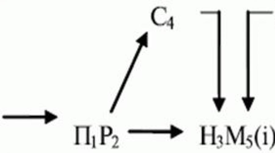
In general, the functional structure of the process concept is characterized by a sequence of transformations of the manufactured product from the initial state at the procurement stage to states C 1, WITH 2 , With n at intermediate and final stages. This transformation is carried out in levels. The design process at each level is a multivariate procedure. Based on one design option ( k-1)-th level, many more detailed options are formed k-th level.
As a result of design at all levels, a tree of acceptable technological process options is formed that meet the specified technical limitations. The vertices of the tree correspond to the operation of synthesizing design solutions, and the arcs correspond to the resulting versions of these solutions. The arcs of the tree of the last level characterize design options of a given level of detail. To solve multi-level optimization problems on i-level of design, therefore, they receive not a single optimal option, but a group of options close to the optimal one. Among these parameters, choose a solution for ( i+1)-th design level.
The figure shows a model of a multi-level design process with the selection of the most rational solution at the last level: T Z- technical task; C ii- operations of synthesis of design solutions; Rq(k)- design options
When generating the structure of the technological process, we use various methods: design based on typification and group technology; transformation of analogue processes; multi-level iterative method; axiomatic method, etc.
The design of specific technological processes by parametrically adjusting a standard process includes two groups of design operations: searching in a technological data bank for the required standard process and calculating the parameters of each operation (determining time standards, material and labor standards). This method is used for standard products. Algorithms for transforming an analogue process do not contain ready-made logical conditions for selecting operations and transitions. These conditions are determined as a result of analysis of the product and TP analogue. After products and TP analogues are found in the technological data bank (I, TN) an, design is based on the information model C k of a specific product, determine the rational structure and parameters of the manufacturing process:
W: ( C k(I, TN)an),
Where W - analogue process transformation operations.
The transformation is carried out by exclusion and addition methods structural elements into analogous processes based on identifying differences between specific products and analogous products.
The method of eliminating structural elements is based on the fact that from the graph S a(C, A)
, describing the structure of the analogue process, some paths or arcs are excluded
{Cq -1,A q,Cq}
, corresponding to operations or transitions in the processing of surfaces that are missing from a particular product or surfaces of higher precision.
The structure of a specific process is formed as a result of applying the difference graphs
S k ( C 1 ,A 1) = S a(C,A)\ {Cq-1,A q,Cq},
Where C 1 =C\{Cq} - many intermediate states necessary for the manufacture of a specific product; A 1 =A\{Aq) - many technological operations necessary for the manufacture of a specific product.
As a result of using such an operation, the structure of a particular process is simpler than its analogue. The transformation of an analogue process by eliminating structural elements is carried out by establishing the technological similarity of the states of an analogue product with the structure and parameters of a specific product. To do this, in the graph of the functional structure of the analogue technological process, hanging vertices are identified that correspond to the final states of groups of processed surfaces. If C a~ C k , then the operation A included in the processing route of a specific product; otherwise, it is excluded from the analog route.
The method of adding structural elements is based on adding an analogue process to the structure graph S a(S,A) set of arcs {C r -1,A r,Cr} , corresponding to newly introduced operations and transitions for processing the surfaces of a particular product, which are absent in analogous products or have lower accuracy. The structure of a particular process is more complex and is formed as a result of the operation of combining graphs
S k ( C 1 ,A 1) = S a(C,A)U ( Cr-1,A r,Cr} ,
Where C 1 = C U Cr; A 1 =A U A r.
In a number of cases, design problems arise when the transformation of analogue processes is carried out using one or another method
S k ( C 1 ,A 1) = S a(C,A) \ {Cq-1,A q,Cq) U ( Cr-1,A r,Cr}
Transformation of an analogue process by adding structural elements (operations, transitions) involves determining the type and quantity of these elements and their rational arrangement.
The principle of multi-level decomposition
One of the most common methods Overcoming the initial uncertainty of the technological design problem is a multi-level iterative method. Its essence is revealed by a set of principles and statements that determine the nature and structure of design processes.
The design of discrete technological processes and complex objects is divided into several interconnected levels, characterized by a successively increasing degree of detail of design solutions from level to level.
The basis of the principle of multi-level decomposition is the following statements:
1. Design of technological processes for manufacturing products can be divided into 4 levels:
· schematic diagram of the process;
· route technology;
· operating technology;
· control programs.
The first level is characterized by the highest degree of abstraction and determination of only the fundamental features of the structure and function of the technological process. From level to level, the degree of detail of design solutions increases. At the last level, it is brought to instructions and equipment control commands.
2 . The multi-level design process develops from top to bottom, i.e. from the synthesis of general fundamental models at the first level to design solutions of the required level of detail at the next levels. Moreover, the solutions obtained in the previous ( k-1) level, are used as additional initial data for design at k-th level. Thus, information about the TP circuit diagram obtained at the first level serves to synthesize the route at the second level. The development of operating technologies at the third level is carried out on the basis of information about the technological route, and information about the operating technology is used to synthesize control programs.
3 . At all levels except the last, due to insufficient detail of design solutions, the criteria for selecting options are generalized, heuristic. They are gradually refined as they move from level to level, achieving the required accuracy at the last design level.
Thus, at the first level it is impossible to form a criterion that allows choosing one optimal option for the TP circuit diagram. The reason is that the idea of the designed process is of a purely fundamental nature and, as a rule, is clarified at subsequent levels.
4 . At the initial and intermediate levels of design, due to the heuristic nature of the criteria, not one, but several (two or three) most rational solutions are selected from the many synthesized options. The final version of the TP, corresponding to the extreme values of the exact criterion, is determined only at the last level.
5 . Design at each level is divided into a set of the following design operations, iteratively interconnected:
The iterative algorithm of the design process can be represented as follows

Here P is the search for analogous solutions, H is the transformation of analogous processes, C is synthesis various options technology, M - simulation modeling of the processing process, A - analysis of simulation results, E - evaluation of simulation results, Q - optimization, W - selection of the most rational options.
The design process begins with the search for products and technological analogues in the array of technological data banks. If such processes are found, then the logical block R 2 control is transferred to the analog process conversion operation N 3 , if not found - synthesis operations WITH 4 . In this block, a number of TP options are synthesized in a centralized way that satisfy the specified technical requirements and restrictions. The operation of simulation allows, for example, to predict the nature of surface treatment, the resulting errors and the values of technical and economic parameters. Using the "analysis" operation, the reasons for the occurrence of certain deviations and underestimated values of individual local criteria are established. The analysis is carried out on all technical and economic indicators.
The “evaluation” operation checks the degree of fulfillment of the specified technical requirements. Based on the identified local criteria, an integral criterion for the quality of a particular option is determined, and the need to obtain certain of its indicators is established. The “optimization” operation selects the direction for improving the design option in accordance with the model characterizing the relationship of local criteria. As a result of the transformations carried out in the original version, a new improved version appears. Information about it again enters the modeling, analysis, evaluation and optimization blocks. The combination of these operations forms an iterative cycle of the design process.
Over several iterations, the quality of the original version improves. The process ends when the option meets the specified requirements in all main indicators and its further improvement does not lead to a significant improvement in the integral criterion. Using a block R 8, the operations of modeling, evaluation, analysis and optimization are cyclically repeated for all options obtained in search and synthesis operations. As a result, for the “selection” operation, many appropriate options are prepared, from which the most rational ones are then selected.
In the above model, a set of design operations and control blocks defines two design methods: transformation of analog and synthesis objects.
Methods differ in the operations of generating design options. In the first method, this is a search for analogue objects and their transformation, and in the second, a targeted synthesis of design solutions. The remaining operations of the iterative cycle and selection of options are common to both design methods.
As development and implementation experience shows, these methods are widely used in CAD TP. In terms of their capabilities, they do not contradict, but complement each other.
Programs built on the basis of typing methods are characterized by less (30-40%) volume and computer time consumption compared to the multi-level iterative method. In this regard, it is advisable to automate the design of technological processes for standard products on the basis of typification methods, and for other products - by transforming analogue processes and a multi-level iterative method.
So, the entire process of manufacturing a device is considered as a sequence of interconnected technological operations. For example, in the manufacture of a p-n-p transistor with an epitaxial base, the main operations are such as diffusion and oxidation, base and emitter formation. Each operation is characterized by a set of input and output parameters, which, in turn, are the initial data for computer calculations using selected mathematical models.
Thus, in the diffusion and oxidation unit there is a control panel for the diffusion process, with the help of which the parameters of the plate processing process are set, the furnace mode, the duration of the technological cycle are selected, and the process characteristics are adjusted if they deviate from the specified values. At the exit from the oven special device measures the parameters of the plates, the data is transmitted to the control panel, which compares the measured parameters with the specified ones and adjusts the parameters of the diffusion process accordingly, the main one of which is, for example, the thickness of the oxide.
the place of heat treatment in the technological process, they begin to formulate optimal processing operations on machine tools, taking into account the limitations.The problem of forming optimal operations is multivariate in nature, and the range of solutions can be limited to two limiting cases: each transition corresponds to a one-transition operation; all transitions are performed in one operation.
Before starting to solve the problem, the total set of transitions is distributed into subsets while fulfilling the constraints (see Table 12.1). Each column corresponds to the surface treatment route of the product. If there is no transition, the array cells are not filled (set to 0).
The double lines in the table show the possible division of the total set of transitions into subsets. The total set of transitions included in the set and located in some fixed sequence is denoted by numbers that correspond (except for ) to intermediate transition numbers; - number of the last transition, equal to total number There are a lot of transitions.
It is necessary to distribute the available transitions among operations so that the value of the objective function (for example, the cost of performing an operation) of a particular option is minimal.
The formation of operation options begins with combining into an operation maximum quantity transitions. This approach allows you to sharply reduce the number of analyzed options.
To narrow the search area for the optimal combination, use the selection criterion, which allows you to exclude some options from consideration.
At the first stage of selection, technological possible options taking into account the restrictions imposed on the processing sequence, the minimum number of reinstallations and the technological capabilities of the equipment.
At the next design stage, when the option is generated for a specific machine model, it is checked to ensure that the restrictions on processing accuracy and surface roughness are met.
If the option is implemented, the corresponding value of the objective function is calculated. The calculation continues until all transitions are distributed among operations and the value of the objective function is found. When the calculation results for two steps (iterations) are received, they must be compared and the best one selected. If last option worse than the penultimate one, then based on the dominance rule, the calculation is stopped.
| No. of the processed surface of the product | |||||||||||
|---|---|---|---|---|---|---|---|---|---|---|---|
| 1 | 2 | … | 1 | … | n | … | … | … | … | … | … |
| 11 | 12 | … | i | … | 1n | 1 | 1 | … | 0 | … | 1 |
| 21 | 22 | … | 2i | … | 2n | … | … | … | … | … | … |
| … | … | … | … | … | … | M | 0 | … | m | … | m |
| K1 | k2 | … | ki | … | kn | P | 0 | … | Pi | … | Pn |
If the option is improved, the calculation continues until the optimal one is obtained. Then in place of the worst they form new option. Dominance Rule is that a further reduction in the number of transitions in operations leads to an increase in the number of operations and an increase in time and technological cost of processing. Options for forming processing operations according to the described methodology are assessed based on the given costs. Thus, if known technological route processing of the part, it is possible to adjust it according to the composition and content of individual operations, as well as according to the type of equipment used.
12.3. General operating technology design algorithm
Let's consider the general design algorithm operating technology .
In accordance with the nature of the problems to be solved and the structure of the criterion for optimal design, the synthesis of technological operations is divided into four components (Fig. 12.1). In the first, the most rational shape, allowances, tolerances and inter-operational dimensions of the product received for surgery are determined, i.e. condition.
The second part of the algorithms is associated with the selection of elements of the product surface treatment system (models of equipment, fixtures, main, auxiliary and measuring instruments) and spatial layout of instrumental adjustment of equipment.

Rice. 12.1.
The algorithms of the third part carry out the synthesis of the temporal structure of the operation, i.e. they clarify the composition of transitions, determine the order of their execution and the nature of the combination in time.
The fourth part includes algorithms for determining the parameters and technical and economic characteristics of the operation.
For simple operations, a number of algorithms may be missing. For example, in a single-transition operation, the algorithm for determining the sequence of transitions is omitted, and in some operations, algorithms for generating tool setups and distributing transitions among positions are not needed. These features are taken into account when establishing the structural composition of algorithms for designing specific operations. Control algorithm from general scheme certain algorithms are excluded or added depending on the purpose and goals achieved in each specific case.
The result of computer-aided design is an individual technological process, designed in the form of a route map, which contains information about the order of operations and transitions, about equipment and accessories, about the modes of individual technological operations and a number of other information used to organize the manufacture of electronic equipment.
So, we considered three levels for computer-aided TP design systems:
- schematic diagram design;
- technological route design;
- design operating technology.
The design process goes from level to level and at each level is iterative with the accumulation of experience, generalization and adjustment at each level (Fig. 12.2).
These results can be used to develop standard, group algorithms and technological analogues.
Through the operation “generalization” of the accumulated experience from the number of previously designed technological processes, standard design solutions, standard and group algorithms are formed. The value of heuristic self-selection criteria is improved, the structure and parameters of synthesis, analysis and optimization algorithms are improved. The generalization of the accumulated experience is carried out in human-machine design mode with the operational display of analogue processes on display screens.
As a result of training and self-learning, algorithms for the synthesis of design solutions and heuristic criteria for intermediate self-selection become more effective. Instead of generating a large number of possible options, a smaller number of the most promising design solutions (options) are synthesized purposefully, taking into account positive past experience. By improving the values of heuristic criteria in the process of self-learning, at each intermediate stage, a smaller number of the most rational options are selected for further design than before, improving the initial option to the required degree of perfection.
Based on the analysis of design and technological documentation in the process of developing design algorithms, a fund of information is created for the automated design of technological processes for the production of RES elements; this fund is supplemented in the process of functioning of CAD.
Test questions and exercises
- What does operating technology include?
- What do you need to know to build an operation?
- What does a computer-designed route include?
- What factors influence the design of operations?
- What is included in the task of forming an optimal operation?
- What initial data are used when designing TP using a computer?
- That is technological limitations, defining the acceptable options for TP manufacturing at the enterprise?
- What determines the structure of a technological operation?
- How is the number of transitions in an operation determined?
- Name the technological limitations that determine the acceptable manufacturing options for technological processes at the enterprise.
Send your good work in the knowledge base is simple. Use the form below
Students, graduate students, young scientists who use the knowledge base in their studies and work will be very grateful to you.
Posted on http://www.allbest.ru/
Algorithms for designing technological operations
1. Initial data for designing technological operations
2. Formation of an optimal operation
3. General algorithm operating technology design
1 . Initial data for designing technological operations
Designing operations is a multivariate task. To construct an operation, it is necessary to know the route for processing the workpiece, the layout of its installation, which surfaces and with what accuracy were processed in previous operations. The route designed with the help of a computer includes the content of operations, the model of equipment, the name of the device and tool.
The structure of operations is influenced by a number of factors:
Product design (size, weight, configuration);
Technical requirements for its manufacture (tolerances for dimensions and mutual arrangement elements);
Type of workpiece;
Release program;
Equipment model;
Device design.
Technological operations provide a complex structure, the elements of which are technological transitions. These components of the technological process (TP) are interconnected by various relationships, the main ones being temporal, spatial, logical and mathematical.
When optimizing transitions, their number and sequence of execution, modes, allowances for intermediate dimensions, time standards, intermediate (technological) tolerances, number of adjustments, adjustment and technological dimensions are determined.
The task of forming an optimal operation includes organizing and breaking down total set of transitions (set) into subsets taking into account the presence of heat treatment, minimizing the number of workpiece installations and idle tool movements. At the stage of forming operations, time standards are calculated and the choice of equipment, devices and tools is clarified.
Information base design process includes reference and normative data And technical and economic indicators.
The set of possible options forms the region of feasible solutions, in which it is necessary to find the best of all specific conditions. Since the problem under consideration is preceded by the choice of the option and type of equipment, the feasible solutions contain all possible combinations of parameters in their different sequences, taking into account the accuracy of the product, the characteristics of the equipment and the tool.
Let's consider the construction of a TP model using the example of manufacturing elements of radio-electronic equipment (REA).
It is known that technological processes for the manufacture of electronic components are in many cases based on mechanical, thermal, mechanothermal and chemical processing.
For example, when considering hierarchical systems for automated control of heat treatment operations (metallization, soldering, annealing) Special attention is given to shaping primary elementscops REA designs. These primary elements can be obtained by various surface treatment operations, namely:
Casting into metal molds;
Cold and hot stamping;
Upsetting, casting and pressing of polymer materials;
Pressing and sintering of powdered materials;
Turning, drilling, milling, grinding and other processing methods.
At the same time, it is indicated that any primary structural element of a REA can be obtained not in one, but in several ways (for example, casting, pressure, mechanical processing). Preference is given to a method that, in the conditions of a particular production, provides higher productivity and efficiency, the required technological accuracy and creates conditions for mechanization and automation of technological processes.
Another characteristic of shaping technology is that the manufacture of primary structural elements of REA can be carried out using one or another structural option technology, equipment with different technical and economic parameters.
Let the number of transitions be equal to p, and the number of positions on the machine equal to. To perform the th transition
at any position time ti is required, and to complete the transition j-th position it takes time where
In addition, before the -th transition is executed, transitions must be executed (a set composed of indices of those transitions that must be executed before the -th transition).
then equality
indicates that the th transition will be performed at at least one position.
The number of transitions performed at the th position does not exceed if
The distribution of all transitions among machine positions with the combination of several transitions in one position is also carried out taking into account technological rules and operating experience of such equipment. Thus, there are several groups of restrictions. The first of them is related to the requirements for a certain order of transitions.
Another group of restrictions affects the possibility of combining several transitions in one operation
; (here - an integer). (5)
A group of restrictions on the total processing time at each position can be provided, taking into account the working and idle strokes of the tool
where R is the regulated processing time at each position. All restrictions can be written in general form:
where is the set of indexes of positions at which the - transition can be performed.
The optimal number of transitions to each surface and the optimal sequence of their execution are determined at the previous levels of operation construction. When forming an optimal operation, it is necessary to combine the execution of transitions of a particular number of surfaces on one machine. To do this, it is necessary to order the total set of transitions and divide them into sets, taking into account restrictions that are similar to the restrictions when distributing transitions among the positions of a multi-position machine.
2. Phoshaping the optimal operation
To formulate an optimal operation, the method of sequential analysis of options is used. According to the scheme of sequential analysis, as a result of comparison, the dominance of some options over others is established. After this, a rule for filtering out options is formed. Knowing the technological capabilities of the equipment, optimal quantity and the sequence of transitions, as well as the place of heat treatment in the technological process, begin to formulate optimal machining operations on machine tools, taking into account the constraints.
The problem of forming optimal operations is multivariate in nature, and the range of solutions can be limited to two limiting cases: each transition corresponds to a one-transition operation; all transitions are performed in one operation.
Before starting to solve the problem, the total set of transitions is distributed into subsets while fulfilling the constraints (Table 1). Each column corresponds to the surface treatment route of the product. If there is no transition, the array cells are not filled (set to 0).
The double lines in the table show the possible division of the total set of transitions into subsets. The total set of transitions included in the set and located in some fixed sequence is denoted by numbers that correspond (except) to intermediate transition numbers; - the number of the last transition, equal to the total number of transitions in the set. It is necessary to distribute the available transitions among operations so that the value of the objective function (for example, the cost of performing an operation C_(o)n) of a particular option is minimal.
Table 1. No. of the processed surface of the product
|
No. of the processed surface of the product |
||||||
The formation of operation variants begins with combining the maximum number of transitions into an operation. This approach allows you to sharply reduce the number of analyzed options.
To narrow the search area for the optimal combination, a selection criterion is used that allows one to exclude some options from consideration.
At the first stage of selection, technological possible options are identified, taking into account the restrictions imposed on the processing sequence, the minimum number of reinstallations and the technological capabilities of the equipment.
At the next design stage, when the option is generated for a specific machine model, it is checked to ensure that the restrictions on processing accuracy and surface roughness are met.
If the option is implemented, the corresponding value of the objective function is calculated. The calculation continues until all transitions are distributed among operations and the value of the objective function is found. When the calculation results for two steps (iterations) are received, they must be compared and the best one selected. If the last option is worse than the penultimate one, then based on the dominance rule, the calculation is stopped.
If the option is improved, the calculation continues until the optimal one is obtained. Then, in place of the worst, a new option is formed. The rule of dominance is that a further reduction in the number of transitions in an operation leads to an increase in the number of operations and an increase in time and technological cost of processing. Options for forming processing operations according to the described methodology are assessed based on the given costs. Thus, if the technological route for processing a part is known, then it can be adjusted according to the composition and content of individual operations, as well as according to the type of equipment used.
3. General algorithm for designing operating technology
The first part of the operational technology design algorithms determines the processing modes and the choice of technological equipment. Any operational technology, including the production of electronic components, is built according to the following algorithm.
Rice. 1. General algorithm for designing operating technology
The second part of the algorithms is associated with the selection of elements of the product surface treatment system (equipment models, fixtures, main, auxiliary and measuring tools) and the spatial layout of instrumental equipment setup.
The algorithms of the third part carry out the synthesis of the temporal structure of the operation, that is, they clarify the composition of transitions, determine the order of their execution and the nature of their combination in time.
The fourth part includes algorithms for determining the parameters and technical and economic characteristics of the operation.
For simple operations, a number of algorithms may be missing. For example, in a single-transition operation, the algorithm for determining the sequence of transitions is omitted, and in some operations, algorithms for generating tool setups and distributing transitions among positions are not needed. These features are taken into account when establishing the structural composition of algorithms for designing specific operations. The control algorithm excludes or adds certain algorithms from the general scheme, depending on the purpose and goals achieved in each specific case.
The result of computer-aided design is an individual technological process, designed in the form of a route map, which contains information about the order of operations and transitions, about equipment and accessories, about the modes of individual technological operations and a number of other information used to organize the manufacture of electronic equipment.
So, we considered three levels for computer-aided TP design systems:
· design of a schematic diagram;
· design of technological route;
· design operating technology.
The design process goes from level to level and at each level is iterative with the accumulation of experience, generalization and adjustment at each level (Fig. 2).
These results can be used to develop standard, group algorithms and technological analogues.
Through the operation of “generalization” of accumulated experience from a number of previously designed technological processes, standard design solutions, standard and group algorithms are formed. The value of heuristic self-selection criteria is improved, the structure and parameters of synthesis, analysis and optimization algorithms are improved. The generalization of the accumulated experience is carried out in the mode of human-machine design with the operational display of analogous processes on display screens.
As a result of training and self-learning, algorithms for the synthesis of design solutions and heuristic criteria for intermediate self-selection become more effective. Instead of generating a large number of possible options, a smaller number of the most promising design solutions (options) are synthesized purposefully, taking into account positive past experience. By improving the values of heuristic criteria in the process of self-learning, at each intermediate stage, a smaller number of the most rational options than before are selected for further design.
Consequently, a self-learning loop, based on the use of design experience, can improve the quality of design solutions and dramatically reduce the cost of computer time.
As a result of targeted synthesis and intermediate selection at each level, not all possible options are generated, but only the most promising ones. They may have shortcomings that are identified through analysis and evaluation operations, and then eliminated by optimization algorithms. A similar situation is observed when automating the design of TP analogues.
As a result, we come to the need to organize an iterative model of the design process, the main feature of which is the consistent improvement of the original version to the required degree of perfection. Based on the analysis of design and technological documentation in the process of developing design algorithms, a fund of information is created for the computer-aided design of technological processes for the production of RES elements.
design technological operation
Rice. 2. Model of an automated design system with storage and generalization of design experience at each level.
As a result, we come to the need to organize an iterative model of the design process, the main feature of which is the consistent improvement of the original version to the required degree of perfection.
Based on the analysis of design and technological documentation in the process of developing design algorithms, a fund of information is created for the automated design of technological processes for the production of RES elements; this fund is supplemented in the process of CAD functioning.
1. What does it include operating technology?
2. What do you need to know to build an operation?
3. What does a computer-designed route include?
4. What factors influence the design of operations?
5. What is included in the task of forming an optimal operation?
6. What initial data are used when designing TP using a computer?
7. What is technological limitations, defining the acceptable options for TP manufacturing at the enterprise?
8. What determines the structure of a technological operation?
9. How is the number of transitions in an operation determined?
Name technological limitations, which determine the acceptable options for TP manufacturing at the enterprise.
Posted on Allbest.ru
Similar documents
Basic concepts of optimal design. Stages of solving a design problem radio-electronic device With optimal characteristics using parametric optimization methods. Multicriteria optimization in problems with constraints.
abstract, added 03/04/2009
Methods and stages of designing electronic equipment. The role of programming language in computer-aided design systems. a brief description of computers used in solving problems of automation of electronic equipment design.
abstract, added 09.25.2010
Characteristics of design stages electronic systems. Application of high-level graphical and text editors during the design process. Configuration options for hardware. Sequence of design procedures of the architectural stage.
test, added 11/11/2010
Computer aided design process in P-CAD design system printed circuit board power amplifier. Packing the circuit onto the board. Automatic PCB routing procedure. Text description of the electrical circuit diagram.
course work, added 01/18/2014
Analysis current state design of transceiver radio devices. Description of decision support systems, prospects for using such systems in the field of design. Calculation of the bandwidth of the high-frequency path of the receiver.
thesis, added 12/30/2015
Algorithms for the design of control systems for radio-electronic equipment: main tasks, layout criteria. Layout algorithms using integer programming techniques. Iterative algorithms for improving layout.
test, added 11/23/2013
Familiarization with the features of working in the environment of the computer-aided design system "Max+Plus II". Analysis of the stages of development of specialized digital devices. Characteristics of the circuit after changing addresses. Consideration of ways to configure adders.
test, added 01/03/2014
Study of methods for designing, calculating and modeling amplifiers using ARPA. Calculation of the voltage gain of an open-loop amplifier. Output, input stage and calculation of capacitive elements. Gain and feedback circuit.
course work, added 03/05/2011
The study of the basic principles of constructing databases - a named collection of data reflecting the state of objects and their relationships in the subject area under consideration. Database management system. Concepts of their construction and design stages.
test, added 12/14/2010
Typical scheme process of computer-aided design of RES. Classification of design problems solved during the design process of RES. CAD structure, mathematical support, linguistic support. Dialogue languages, their varieties and types.
End mill manufacturing process
Rationale for using the tool.
For example, it is necessary to develop an end mill design for processing a groove that performs two operations simultaneously: cutting a groove to a given depth and chamfering at an angle of 45.
The main parameters of the cutter that must be taken into account:
Tooth direction
Teeth design: sharpened / backed
Teeth material Number and size of teeth (For rough milling - cutters with a large circumferential pitch and a small number of large teeth. For finishing milling and milling of fragile materials - cutters with small circumferential pitch and big amount small teeth)
· Design of cutters: solid, composite (with soldered cutting elements) and prefabricated (with mechanical fastening non-sharpenable replaceable polyhedral inserts)
Installation method on the machine spindle: attachment (with hole) / end (with shank)
Design. Despite the fact that design engineers offer hundreds different types and varieties of cutters, they all have a range common elements(see picture).
Device of end mills.
(using the example of a round cutter and a straight slot cutter)

Cutting edges. A cutter may have one, two or more cutting edges. Single edge cutters are used when high productivity is required, in relation to which surface cleanliness is of secondary importance. Most cutters have two or more cutting edges, which provides a kind of balance between cut quality and productivity.
The cutting edges of the cutter can be made of high-speed steel (abbreviated as HSS) or carbide (TCT). The latter, as a rule, are somewhat more expensive.
To ensure that the cutter can be immersed in the material at any location on the workpiece, the cutter must have end cutting edges (like the slot cutter shown in the figure).
Shank cutters are characterized by diameter and length. Obviously, the diameter of the shank must match the diameter of the router collet. Milling cutters sold in Russia, as a rule, are supplied with collets with a diameter of 8 and 12 mm, or only 8 mm (typical for low-power models). Collets of the indicated dimensions are standard in European countries. Tools intended for the American market are designed to use cutters with ¼” (6.35 mm) and ½” (12.7 mm) inch shanks. However, many manufacturers, both European and American, offer additional collets in inch or, conversely, metric sizes for their milling cutters.
The shank can also be conical, as they call a Morse taper. There is a conical hole of the appropriate size (socket) for it in the spindle or tailstock of the machine. Designed for quick tool changes with high centering accuracy and reliability.
When developing new cutter designs, the following basic requirements are met.
The number of teeth should be as large as possible, since the minute feed, i.e., processing productivity, proportionally depends on it.
At the same time, the teeth must be strong enough, and the spacing between them, the shape and surface roughness of the chip flutes must ensure reliable placement and removal of chips (the latter is especially important for end mills that machine deep grooves). In some cases, for example, when continuous continuous chips are formed, the front surface of the teeth of end mills is stepped to crush the chips.
Equipment selection
The task of this section is to select for each process operation such equipment and devices that would ensure the production of parts of a given quality and quantity with minimal costs.
When choosing the type and model of metal-cutting machines, we will be guided by the following rules:
1) The productivity, accuracy, dimensions, and power of the machine must be minimal and sufficient to ensure that the requirements for the operation are met.
2) The machine must provide maximum concentration of transitions to operations in order to reduce the number of operations, the amount of equipment, increase productivity and accuracy by reducing the number of workpiece rearrangements.
3) The equipment must meet safety, ergonomic and environmental requirements.
If for some operation several machine models satisfy these requirements, then for the final selection we will carry out a comparative economic analysis. We select equipment in the following sequence:
1) Based on the shape of the surface being processed and the processing method, we select a group of machines.
2) Based on the position of the surface being processed, select the type of machine.
3) Based on overall dimensions workpiece, dimensions of machined surfaces and processing accuracy, we select the standard size (model) of the machine. Data on the choice of equipment is entered into table 5.1.
Table 5.1
Choice technological equipment
| No. op. | Operation name | Type, model of equipment | Machine fixture |
| Procurement | Horizontal band saw UE-330A | Self-centering vice with prismatic jaws according to GOST 12195-66 | |
| Turning | |||
| Welding | Welding machine butt welding reflow method MSMU-150 | Specialist. Conductive prisms | |
| Annealing | |||
| Test | - | - | |
| Turning | Screw-cutting lathe 1K62 | 3-jaw chuck GOST 2675-63 | |
| Turning | 3-jaw chuck GOST 2675-63 | ||
| Turning | Turret lathe 1N365BP | 3-jaw chuck GOST 2675-63 | |
| Turning | Screw-cutting lathe 1K62 | 3-jaw chuck GOST 2675-63 | |
| Milling | Vertical milling machine 6T104 | 3-jaw chuck GOST 2675-63 | |
| Milling | CNC milling machine MANO-700 | Special collet chuck | |
| Test | |||
| Thermal | |||
| Cylindrical foiling | Drive chuck | ||
| Cylindrical foiling | Cylindrical grinding machine 3131 | Drive chuck | |
| Grinding | Specialist. CNC grinding machine 55С CNC6 | Special collet chuck | |
| Test | |||
| Marking |
An example of milling a crankcase pipe with a new cutter
Time of processing
To determine the processing time, it is necessary to determine the cutting conditions. We will assign the cutting modes to be the same as for the basic version of processing the crankcase pipe with two types of tools, namely:
Feed when cutting into cutter:
Sв= 100 mm/min
Feed rate for longitudinal milling of a pipe groove:
Sp = 200 mm/min
Accelerated feed when approaching/retracting the cutter:
Sу= 5000 mm/min
Then we find the machine processing time using the formula:
ТМ = Lв / Sв + Lп / Sв + Lу / Sу, where:
Lв – stroke length when cutting the cutter, 10 mm
Lп – stroke length of the cutter during transverse movement, 205 mm (according to the drawing)
Lу – stroke length during accelerated movements of the cutter during approach to the workpiece and removal, 400 mm.
Machine time is:
TM= 10/100 + 205/200 + 400/5000 = 1.185 min
We find the unit time for this operation using the formula:
Tsht=Tv+Tm
TV – auxiliary time, let’s take it as in the basic version (based on practice results),
TV=0.57 min
Hence the unit time for the operation will be:
Tsht=0.57+1.185=1.755 min
Since 2 workpieces are processed at once in one operation, the piece time in terms of 1 workpiece will be:
Tsht1 = Tsht/2
Tsht1 = 1.755/2 = 0.878 min
Sequence of development (design algorithm) of the technological process.
1. Study of the technical specifications and choice of type and organizational form production process.
2. Selection of finishing processing methods that ultimately shape the quality of the tool for each surface.
3. Selection of a workpiece that most fully satisfies the economical production of tools under given or selected production conditions.
4. Comparison of the shape, size and quality of the workpiece with the finished tool and determination of the nature of intermediate types of processing: turning, milling, drilling, etc.
5. Development of a technological route, i.e. sequences of all types of processing by transitions.
6. Selection of technological bases. The requirements for them are the same as in general mechanical engineering: the desire for the unity of design, technological and measurement bases, as well as for their constancy, i.e. to invariance when performing various technological operations. Selection of primary roughing bases that allow the workpiece to be correctly oriented for processing with the required accuracy of the main technological bases.
7. Selection of technological equipment and accessories.
8. Development of route technology.
9. Development of operating technology for serial and mass production conditions:
§ a) calculation of operational allowances and tolerances;
§ b) determining the size and shape of the workpiece;
§ c) standardization of technological operations.
10. Comparison of the economic efficiency of several technological process options and selection of the optimal one.
11. Final revision of the selected technology option. Development of detailed operational cards for mechanical, thermal, chemical-thermal treatment, welding, soldering, etc., as well as technical control cards.